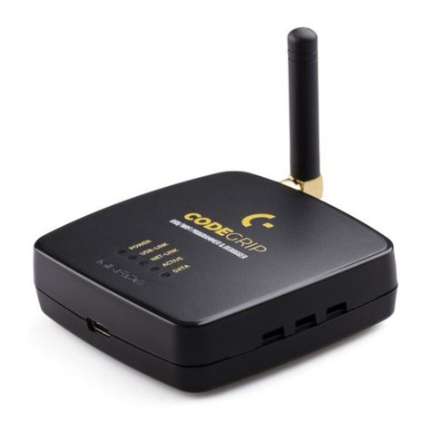
Mikroe Codegrip User manual

P A G E 1
C O D E G R I P U S E R M A N U A L
USER MANUAL

Thank you for choosing Mikroe!
We present you the ultimate debugger and programmer over USB/WiFi solution for embedded development.
Elegant on the surface, yet extremely powerful on the inside, we have designed it to inspire outstanding achievements.
And now, it’s all yours.
Enjoy premium.

Table of contents
Introduction 5
1. Installing CODEGRIP Suite 6
2. CODEGRIP 8
2.1 USB connectivity 9
2.2 WiFi connectivity 9
2.3 Target connector 10
2.4 CODEGRIP adapters 11
2.5 LED indicators 13
3. CODEGRIP Link structure 14
2.1 Link types 14
2.2 Link states 14
4. CODEGRIP Suite overview 16
4.1 Menu section 17
4.2 Menu item section 17
4.3 Shortcuts bar 17
4.4 Status bar section 18
5. CODEGRIP Suite explained 19
5.1 Target MCU 19
5.2 CODEGRIP 28
5.3 POWER 38
5.4 OPTIONS 38
5.5 HELP 40
Troubleshooting 42


CODEGRIP is a unified solution, designed to perform
programming and debugging tasks on a range of different
microcontroller devices (MCUs) based on the ARM® Cortex®-M
architecture. By bridging differences between various MCUs,
it allows a huge number of MCUs from several different
MCU vendors to be programmed and debugged. Although
the number of supported MCUs is absolutely huge, more
MCUs might be added in the future, along with some new
functionalities.
Thanks to some advanced and unique features such as
wireless connectivity and USB-C connector, the task of
programming of a huge number of various ARM® Cortex®-M
based microcontrollers becomes seamless and effortless,
providing users with both the mobility and the complete
control over the microcontroller programming and debugging
process. The USB-C connector offers improved performance
and reliability, compared to traditionally used USB Type A/B
connectors. Wireless connectivity redefines the way the
development board can be used.
The graphical user interface (GUI) of the CODEGRIP Suite is
clear, intuitive, and easy to learn, offering a very pleasant user
experience. The embedded HELP system provides detailed
guidelines for every aspect of the CODEGRIP Suite.

P A G E 6
C O D E
G R I P U S E R M A N U A L
INSTALLATION
2.
Select the
destination
folder
1.
Start the
installation
1. Installing CODEGRIP Suite
The installation process is easy and straightforward.
Download CODEGRIP Suite software application from the link www.mikroe.com/setup/codegrip and follow the steps
below.
3.
Select the
components
to install
4.
License
agreement

P A G E 7
C O D E G R I P U S E R M A N U A L
6.
Start the
installation
process
5.
Select the
start menu
shortcuts
INSTALLATION
7.
Installation
progress
8.
Finish the
installation
process

P A G E 8
C O D E
G R I P U S E R M A N U A L
P A G E 8
C O D E
G R I P U S E R M A N U A L
The CODEGRIP device offers a set of unique and innovative
functionalities, some of which have never been used before
on a similar device. These functionalities include wireless
programming and debugging, power monitoring, advanced
debugging options with the SWO support, and more.
The CODEGRIP device comes in two different types: as a
stand-alone device and an integrated on-board module. This
manual will be focused on the stand-alone CODEGRIP device.
In order to better understand how this device is operated, this
chapter will give you a brief overview of its basic hardware
functions.
2. CODEGRIP
P A G E 8 CODEGRIP

P A G E 9
C O D E G R I P U S E R M A N U A L
P A G E 9
C O D E
G R I P U S E R M A N U A L
2.1 USB connectivity
2.2 WiFi connectivity
The USB-C connector is the latest upgrade of the conventional USB A/B
type connectors, typically found on most personal computers today. The
USB-C connector has many advantages over the USB type A/B connector
such as the completely symmetrical design which reduces the possibility
of the connector misalignment and the damage it might cause, higher
current capability, and more. However, if there is not appropriate USB-C
connector on the host PC, a USB-C cable adapter can be used.
The CODEGRIP device can be linked with the CODEGRIP Suite over the WiFi
network, allowing it to program and debug the target MCU wirelessly. This
is a revolutionary new feature, which allows some unique usage scenarios,
currently not available on any other programming/debugging solution in
the world. The WiFi connectivity option offers a complete autonomy of
the development system. Running a toxic gas sensor application while
debugging the firmware in real time, programming it with a new firmware
during exposure, having sensor responses collected and logged remotely
CODEGRIP
P A G E 9
N O T ETo use the WiFi functionality, a separate registration code is required. It
can be bought from the official Mikroe online store www.mikroe.com
from several different base points, debugging drone firmware while it is in
mid-air… This is just a simple example of what CODEGRIP can offer.
The WiFi module on the CODEGRIP device has an integrated chip antenna,
which allows good WiFi reception. However, if a stronger WiFi signal is
required, the CODEGRIP device offers an SMA connector for an external
WiFi antenna.
The WiFi link can be protected by a password, or by the MAC address
filtering option.
2.3 Target connector
CODEGRIP firmware
The CODEGRIP device can be used with any hardware, equipped with the
standard JTAG/SWD programming header. Packed in a sturdy casing with
rubber feet, it can be used independently, bringing all the powerful features
to a third-party hardware.
The CODEGRIP device is based on the powerful 32-bit MCU, which utilizes a
complex firmware to provide all the required functionalities. The firmware
will be continuously improved so that additional optimizations, functions,
and support for new MCU families might be added in the future. Therefore,
the complete CODEGRIP programming environment is designed so that
the firmware upgrade process is effortless and easy.
On the bottom of the CODEGRIP device there is the sticker which contains
additional information.
∫ Supported MCU family/architecture
∫ Unique serial number
∫ Unique WiFi MAC address
SWDIO/TMSVCC-TGT
SWDCLK/TCK
GND
SWO/TDO
GND
TDI
TGT-RESET
PROG MUX/GND
TRACECLK
GND
TRACEDATA-0
GND
TRACEDATA-1
GND
TRACEDATA-2
GND
TRACEDATA-3GND
The CODEGRIP device is equipped with the target MCU connector, which
contains JTAG/SWD and power supply pins. This connector is used to
interface the CODEGRIP device with the target MCU, allowing it to perform
programming and debugging operations, to provide the power supply for
the target MCU, and to be used as the power input when the CODEGRIP
device is powered from the connected development board.
N O T E When the connected host board provides power to the CODEGRIP
device, CODEGRIP input voltage must be in range 2.5V to 10V.

JTAG/SWD programming/debugging headers may vary across different
hardware applications. To ensure compatibility with various header
configurations there is a set of different adapters available as an additional
purchase option.
2.4 CODEGRIP adapters

CODEGRIP
CODEGRIP

USB-LINK
Indicates that the
connection has been
established via USB
NET-LINK
Indicates that the
connection has been
established via WiFi
ACTIVE
Blinking LED indicates that the
CODEGRIP device is
in the bootloader mode
Steady ON LED state indicates
the normal operation of the
CODEGRIP device
DATA
Indicates the data
transfer between the
target MCU and the
CODEGRIP device
2.5 LED indicators
There are five LED indicators on the CODEGRIP device, used to indicate
different states of the device, providing visual feedback to the user.
POWER
Indicates the
presence of
the power
supply

P A G E 14
C O D E
G R I P U S E R M A N U A L
LINK STRUCTURE
3. CODEGRIP link structure
CODEGRIP Suite can detect multiple CODEGRIP devices. In addition, a
single CODEGRIP device can be operated by multiple software applications.
To avoid any ambiguity, CODEGRIP utilizes the concept of links.
CODEGRIP Suite uses a link to the specific CODEGRIP device, in order to send
commands and receive responses. The link can be created, opened, and
destroyed by the user, employing some specific functions of CODEGRIP Suite.
Based on the link and its state, CODEGRIP Suite can always unambiguously
know which CODEGRIP device to use, and if the specific CODEGRIP device
is currently available. A single CODEGRIP device can have links to multiple
CODEGRIP Suite applications, while CODEGRIP Suite can have a link to only
a single CODEGRIP device at time. Still, it can easily switch the link to any
CODEGRIP device detected during the scanning process.
3.1 Link types
3.2 Link states
Depending on what type of interface is used to establish the link, there are
two types of links available: the USB link, and the WiFi link.
Each link has several different states recognized by the CODEGRIP Suite.
The link is Closed: the CODEGRIP device is not available over the
communication interface (USB or WiFi). Either it is disconnected,
nonresponsive, turned OFF, or otherwise unavailable.
The link is Available: the CODEGRIP device is available over the
communication interface (USB or WiFi). Communication packets can
reach the CODEGRIP device, and it is able to send back the response.
The link is Blocked: this state indicates that the link was blocked because
the specific CODEGRIP device is busy servicing another link.
When CODEGRIP Suite actively uses the link for issuing commands to a
linked CODEGRIP device, other applications linked to the same CODEGRIP
device will have their links in a blocked state. As soon as the task is
complete, those links will revert to the available state.
The indicator showing the current state is visible at the status bar at
the bottom of the Suite. More detailed description about the Shortcut bar
commands find in the Chapter 4.
N O T E USB link is the primary link and it has the highest priority. Some
operations, such as the firmware update, are exclusively used with
the USB link. When the USB link is active, all the WiFi links to that
specific CODEGRIP device will be forced to a closed state.


P A G E 16
C O D E
G R I P U S E R M A N U A L
CODEGRIP SUITE
4. CODEGRIP Suite overview
1 42 3
1. Menu section
2. Menu Item section
3. Shortcut bar
4. Status bar
The graphical user interface (GUI) of CODEGRIP Suite is clear, intuitive, and
easy to use, which ensures a fluid workflow. The main window is divided into
several sections, which are used to display and organize all information,
tools, and options in a consistent and comprehensible manner.
Besides the very informative Help system, CODEGRIP Suite also offers a
short description for the most of its functionalities in a form of a hovering
tooltip. It is enough to keep the mouse hovering above the specific
graphical element for a while, and a small tooltip will pop up, providing
some basic info.
The following chapter explains the GUI layout and its main elements. GUI of
the CODEGRIP Suite can be divided into several sections:

P A G E 17
C O D E G R I P U S E R M A N U A L
CODEGRIP SUITE
4.1 Menu section 4.3 Shortcuts bar
4.2 Menu item section
As already mentioned, all Menu buttons are located in the Menu section (1)
of the CODEGRIP Suite GUI. By clicking a Menu button, one or more Menu
items are unfolded. Menu items are grouped by the type of the function
they are related to. For example, clicking the CODEGRIP Menu button will
unfold Scanning, Configuration, and License Menu items. All these Menu
items are related to configuring and working with CODEGRIP devices, and
therefore they are grouped under the CODEGRIP Menu button.
The Shortcuts bar (3) is another persistent section of the CODEGRIP
Suite GUI, containing controls for the most commonly used commands. It
appears on the top of the Menu item section, just below the title bar. The
only Menu item that does not include the Shortcuts bar is the Programming
Menu item since all the shortcut commands are already included there.
Icons on the Shortcuts bar are used to speed up the workflow, providing
easy access to a set of commands from within any Menu item of CODEGRIP
Suite. This is basically a set of commands otherwise found under the
Programming Menu item, including the most commonly accessed
CODEGRIP commands: WRITE command, DETECT command and VERIFY
command, along with the interface used to select .hex or .bin file.
More detailed description about the Shortcut bar commands find in the
Chapter 5.
When a Menu item is clicked, the Menu item section (2) will display all
the GUI elements available for that specific Menu item. For example,
if the Programming Menu item is clicked, the Menu item section of the
GUI will show some basic information about the target and controls for
MCU programming tasks. Each Menu item will display its own set of GUI
elements in the Menu item section of the GUI interface when clicked.

P A G E 18
C O D E
G R I P U S E R M A N U A L
CODEGRIP SUITE
Update availability indicator: As a part of the startup procedure,
CODEGRIP Suite checks if there is a software update available. If a new
update is available, it will display a notification icon on the status bar,
indicating that there is a new version of CODEGRIP Suite available for
download. This notification icon can be suppressed by configuring the
options found in the OPTIONS/General Menu item.
Selected Device: This text field is used to either display the name of the
CODEGRIP device which is currently linked to CODEGRIP Suite. If the link
has been destroyed by the user, or has not been created yet, the message
“None” will be displayed instead. Hovering the mouse above the message
will highlight it (yellow), indicating that it is clickable.
Two actions will be performed when clicking the message in the Selected
Device field:
∫ If the message “None” is displayed, the Scanning Menu item will be
activated if clicked.
∫ If there is a CODEGRIP device name displayed in this field, the
Configuration Menu item will be activated if clicked.
4.4 Status bar section
The Status bar (4) is located at the very bottom of the GUI and it is used to
provide persistent visual feedback about the CODEGRIP link status. A set of
indicators along with a related text field allowing the user to always know
the status of the CODEGRIP link.
Link status indicator: provides visual feedback about the status of the link.
When working with multiple devices, it is sometimes useful to have visual
indication of the device which is currently linked with the CODEGRIP Suite.
When the Link status indicator is clicked, the linked device will respond by
blinking its ACTIVE LED.
Color-coding scheme examples:

P A G E 19
C O D E G R I P U S E R M A N U A L
PROGRAMMING
5. CODEGRIP Suite explained
As already mentioned, each Menu button contains one or
more related Menu items, and each Menu item contains its
own set of tools and options, displayed in a form of various
GUI elements on the Menu item section. This chapter provides
detailed information on these tools and options.
5.1 Target MCU
Menu items used to interact with the target MCU (the selected MCU upon
which the CODEGRIP device performs various programming/debugging
tasks) are folded under this Menu button. The Menu button is labeled
dynamically, according to the selected target MCU. This allows the user to
always be aware of which MCU is set as the target MCU, regardless of the
currently selected Menu item. There are three Menu items available, folded
under this Menu button: Programming, SWO Trace and Options.

P A G E 20
C O D E
G R I P U S E R M A N U A L
PROGRAMMING
On the bottom of the Menu item section, there is a panel which displays
different status messages during the programming process, along with the
progress bar. Each command returns a message response and displays it
on this panel. In general, messages displayed with green letters indicate a
successful execution, while messages displayed with red letters indicate
an error during the execution of specific command.
Troubleshooting steps required for resolving of issues reported during the
execution of the programming commands are listed at the end of this
manual, in the Troubleshooting section.
5.1.1 Programming
The Programming Menu item displays all the commands, parameters, and
other information, related to the programming process itself.
When the Programming Menu item is clicked, a quick summary of the
selected programming options is displayed on the top of the Menu item
section, grouped under a label which displays the name of the target MCU:
the selected MCU vendor, the programming protocol, connection speed,
the flash size of the target MCU, the connection type, and the reset type.
Below is the interface used to select and display the program file .bin or
.hex file, ready to be uploaded to the target MCU or examined by using a set
of options, accessible by clicking the FLASH button.
There is also the programming interface, composed of a set of buttons,
used to perform various programming commands. These commands will
be explained in this chapter.
Table of contents
Other Mikroe Motherboard manuals

Mikroe
Mikroe EasyMx PRO v7a User manual

Mikroe
Mikroe mikromedia 3 User manual

Mikroe
Mikroe mikromedia 5 User manual

Mikroe
Mikroe MAGNETO click User manual

Mikroe
Mikroe EasyPIC PRO v8 User manual

Mikroe
Mikroe EasyPIC V8 User manual

Mikroe
Mikroe Mikromedia 4 User manual

Mikroe
Mikroe COUNTER click User manual

Mikroe
Mikroe Click RTC3 User manual

Mikroe
Mikroe EasyPIC V8 User manual