Milestone pro MPTP-T70SC-H2 User manual
MPTP-T70SC-H2
18G HDMI Extender with Audio Breakout
All Rights Reserved
Version: MPTP-T70SC-H2_2020V1.0
User Manual

2
Statement
Thanks for choosing this product, please read this user manual carefully before using
this product. The functions described in this version are updated till March, 2020. In
the constant effort to improve our product, we reserve the right to make functions or
parameters changes without notice or obligation.
Safety Precaution
Do not dismantle the housing or modify the module to avoid electrical shock or burn.
Using supplies not meeting the products' specifications may cause damage,
deterioration or malfunction.
Do not expose the unit to rain, moisture or install this product near water.
Install the device in a place with fine ventilation.
Do not twist or pull by force ends of the optical cable. It can cause malfunction.
Do not use liquid or aerosol cleaners to clean this unit.
Always unplug the power to the device before cleaning.
Unplug the power when not used for a long period of time.
Refer all servicing to qualified service personnel.
After-sales Service
We provide limited warranty for the product within three years.
Packing List
1x MPTP-T70SC-H2T Transmitter
1x MPTP-T70SC-H2R Receiver
2x TX Mounting Ears with 4 Screws
2x RX Mounting Ears with 4 Screws
4x TX Plastic Cushions
4x RX Plastic Cushions
1x 3-pin Terminal Block
1x RS232 Cable (3-pin to DB9)
1x Power Adapter (24V DC 1.25A)
1x User Manual
Note: Please contact your distributor immediately if any damage or defect in the
components is found.

3
Product Introduction
Thanks for choosing the MPTP-T70SC-H2 HDMI 2.0 Extender, which consists of a
transmitter and a receiver. It can extend 4K video to distance up to 131 feet (40 meters)
and 1080P video to distances up to 230 feet (70 meters) over a single CATx cable. It
supports audio de-embedded and ARC. It also supports bidirectional IR and RS232
pass-through to control source or display device remotely. PoC feature allows the
transmitter and the receiver can be powered from each other and only one power
adapter is needed in system. Besides passing EDID information from the display, there
are multiple built-in EDID settings can be selected by the 4-pin DIP switch on the front
panel of transmitter. Moreover, the extender supports convenient firmware upgrade
through Micro-USB port.
Features
Supports HDMI 2.0 and the HDMI video resolution up to 4K@60Hz 4:4:4 HDR.
HDMI input supports HDCP 2.2 and the output support HDCP Active or HDCP
Passive mode.
Extends 4K signals to distances up to 131 feet (40 meters) and 1080P signals to
distances up to 230 feet (70 meters) over a single CATx cable.
Supports video resolution up-scaling, the 1080P input can be automatically
upgraded to 4K output.
SPDIF out on receiver for source audio de-embedding.
18Gbps high bandwidth.
Advanced EDID management: multiple built-in EDID settings can be selected.
Test pattern provides a built-in 4K/1080P image for troubleshooting.
Bidirectional IR, RS232 and 24V PoC.
Supports ARC.
Supports CEC pass-through.
Provides LEDs to indicate the current operating status.
Firmware upgrade by Micro-USB port.

4
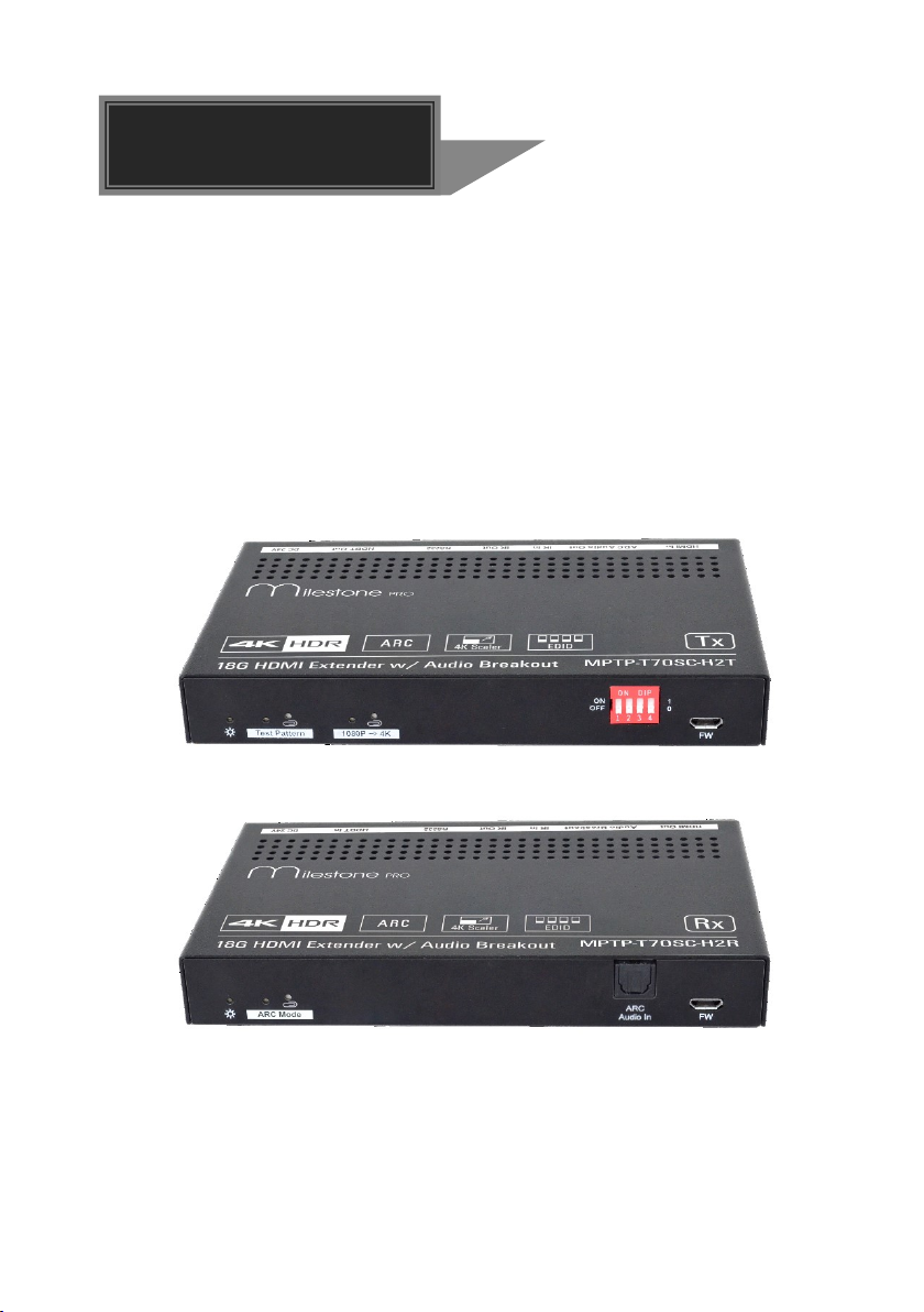
Transmitter Panel Description
①Power LED: The LED illuminates red when power is applied.
②Test Pattern: Press the button with paper clip or other sharp tool to enable the
test pattern, and the left LED illuminates blue, the product generates an image of
1080P/60Hz color bar to output; Press this button again, the left LED blinks blue
at an interval of 500ms, the product generates an image of 4K/60Hz 4:4:4 color
bar to output. Press and hold this button for three seconds again can exit the Test
Pattern mode.
③1080P →4K: Press and hold the button at least three seconds with paper clip or
other sharp tool to enable 1080P to 4K up-scaling, and then the left LED
illuminates blue. Press and hold it again to exit.
④EDID: 4-pin DIP switch for EDID setting and HDCP mode selection. Please refer
to the EDID Management for more details.
⑤FW: Micro-USB port for firmware upgrade and user-defined EDID upload.
⑥HDMI In: Type-A female HDMI input port to connect a HDMI source.
⑦ARC Audio Out: Toslink connector to connect speaker or amplifier for ARC audio
output.
⑧IR In: 3.5mm jack to connect the IR receiver for IR pass-through.
⑨IR Out: 3.5mm jack to connect the IR emitter for IR pass-through.
⑩RS232: 3-pin terminal block to connect the RS232 control device (e.g. PC) or a
third-party device to be controlled.
⑪HDBT Out: RJ45 port to connect the HDBT input port of receiver by CATx
Ethernet cable. The LINK LED illuminates orange when there is a valid HDBaseT
link between the transmitter and the receiver. The HDCP LED illuminates green
when the video contains HDCP content.
⑫DC 24V: DC connector for the power adapter connection.
Tx Rx
LINKHDCP
123 4 5678910 11 12
HDBTOut
HDMI In
IROut
IRIn
ARC Audio Ou t

5
Receiver Panel Description
①Power LED: The LED illuminates red when power is applied.
②ARC Mode: Press the button with paper clip or other sharp tool to enable the
ARC mode, and then the left LED illuminates blue. Press it again to exit the ARC
mode and the LED is off.
③ARC Audio In: Toslink connector to connect ARC audio source device (e.g.TV).
④FW: Micro-USB port for firmware upgrade.
⑤HDMI Out: Type-A female HDMI output port to connect HDMI display (e.g.TV).
⑥Audio Breakout: If the ARC mode is OFF, the Toslink connector is connected to
speaker or amplifier for HDMI source audio de-embedding. Note that if the ARC
mode is ON, this port has no audio output.
⑦IR In: 3.5mm jack to connect the IR receiver for IR pass-through.
⑧IR Out: 3.5mm jack to connect the IR emitter for IR pass-through.
⑨RS232: 3-pin terminal block to connect the RS232 control device (e.g. PC) or a
third-party device to be controlled.
⑩HDBT In: RJ45 port to connect the HDBT output port of transmitter by CATx
Ethernet cable. The LINK LED illuminates orange when there is a valid HDBaseT
link between the transmitter and the receiver. The HDCP LED illuminates green
when the video contains HDCP content.
⑪DC 24V: DC connector for the power adapter connection.
12345678911
10
6
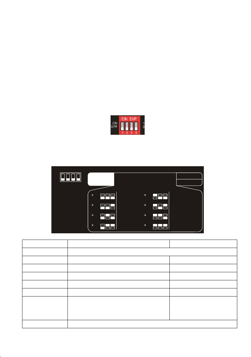
DIP Switch Operation
EDID Management
The Extended Display Identification Data (EDID) is used by the source device to
match its video resolution with the connected display. By default, the source device
obtains its EDID from the first connected display. Meanwhile, since the displays with
different capabilities are connected to the extender, the DIP switch on the front panel
of transmitter can be used to set the EDID to a fixed value to ensure the compatibility
in video resolution.
The switch represents “0” when in the lower (OFF) position, and it represents “1” while
putting the switch in the upper (ON) position.
Switch 1~3 are used for EDID setting. The DIP switch status and its corresponding
setting are shown at the back of the product.
Switch Status
Video Resolution
Audio Format
000
Pass Through
001
1080P
2CH
010
3840x2160@30Hz
2CH
011
3840x2160@30Hz
Multi-CH
100
3840x2160@60Hz
2CH
101
3840x2160@60Hz
Multi-CH
110
3840x2160@60Hz HDR
Multi-CH (Supports PCM
2CH, PCM5.1, Dolby
Digital 5.1,DTS 2CH)
111
User-defined EDID (Upload the EDID by Micro-USB port)
1 2 3
EDID Setting
Default
1 2 3 4
ON
OFF
1
0ON
OFF
4
HDCP Active
HDCP Passive
Pass Through
1080p 2CH
4K/30Hz Multi-CH
ON
OFF
1 2 3
ON
OFF
1 2 3
ON
OFF
1 2 3
ON
OFF
1 2 3
4K/30Hz 2CH
ON
OFF
1 2 3
ON
OFF
1 2 3
ON
OFF
1 2 3
4K/60Hz 2CH
4K/60Hz Multi-CH
4K/60Hz HDR Multi-CH
ON
OFF
1 2 3
User Defined

7
Note:
2CH: Supports LPCM 2CH.
Multi-CH: Supports LPCM 8CH, Dolby TrueHD, DTS-HD , Dolby Digital5.1, DTS
5.1, Dolby Digital Plus.
User-defined EDID Setting
Except directly invoking the built-in EDID, the specific EDID can be customized by
following the below operation process.
1) Rename the user-defined EDID according the following format.
EC_xx_xxxxx_xxxx_xxx.bin
EC: Fixed value
xx: EDID ID. It is “15”.
xxxxx: Video resolution.
xxxx: Refresh rate.
xxx: Audio format.
Example: EC_15_3840x2160_60Hz_ Dolby.bin
2) Connect the FW port of transmitter to the PC with USB cable, and then power on
the transmitter, the PC will automatically detect a virtual disk named of
“BOOTDISK”.
3) Double-click to open the disk, a file named of “READY.TXT” will be showed.
4) Copy the user-defined EDID (such as EC_15_3840x2160_60Hz_Dolby.bin) to
the “BOOTDISK” disk.
5) Reopen the disk to check the filename “READY.TXT” whether automatically
becomes “SUCCESS.TXT”, if yes, the user-defined EDID was imported into the
transmitter and saved as its corresponding EDID ID successfully.
6) Remove the USB cable, and then reboot the transmitter.
7) Now the new EDID can be invoked by setting the DIP switch status to “111”.
8
HDCP Mode
Put the switch 4 on the “ON” position to select HDCP Active mode, or on the “OFF”
position for HDCP Passive mode.
Switch Status
Mode
HDCP
OFF (0)
Passive
(Default)
Automatically follows the HDCP version of source
device.
ON (1)
Active
If the input video has HDCP content, the HDCP
version of HDMI output is HDCP 1.4 for broader
video solution.
If the input video has no HDCP content, the HDMI
output has no HDCP too.
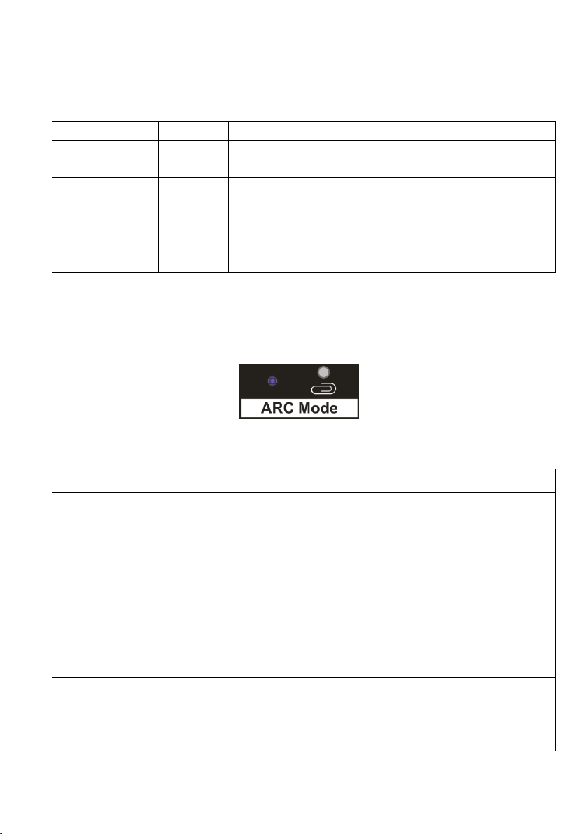
ARC Mode
The front panel of receiver provides a buttons to enable or disable ARC mode, as
below figure shows:
Press the button with paper clip or other sharp tool to enable the ARC mode, and then
the left LED illuminates blue. Press it again to exit the ARC mode and the LED is off.
ARC Mode
Display (e.g.TV)
Audio Transmission Path
ON
ARC is supported.
The TV audio is transmitted from the TV back to
the receiver via HDMI cable, and then it will be
output by the ARC Audio Out port of transmitter.
ARC is not
supported.
Connect the TV to the ARC Audio In port of
receiver with an audio cable. The TV audio is
transmitted from the TV back to the receiver via
the audio cable, and then it will be output by the
ARC Audio Out port of transmitter.
Note that if the ARC mode is ON, the Audio
Breakout port of receiver has no audio output.
OFF
/
The TV audio can’t be back to the ARC Audio Out
port of transmitter. The Audio Breakout port of
receiver is connected to speaker or amplifier for
HDMI source audio de-embedding.
9
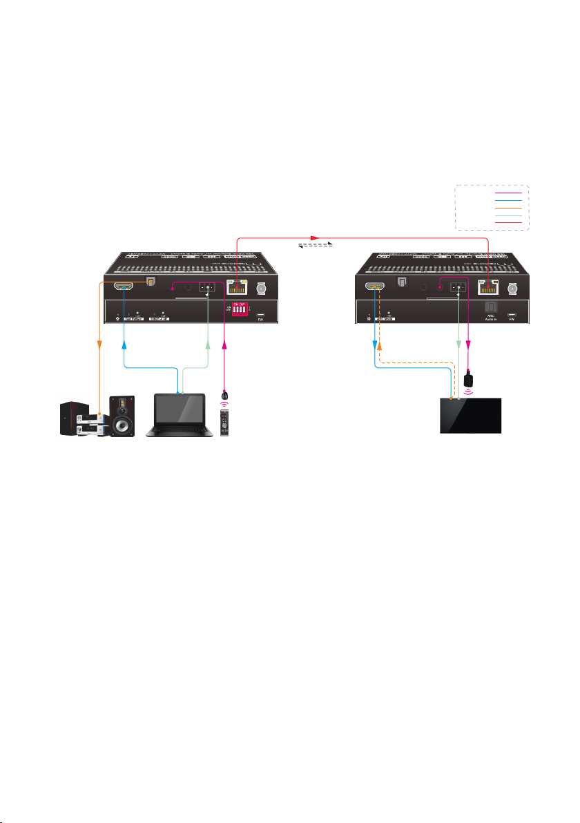
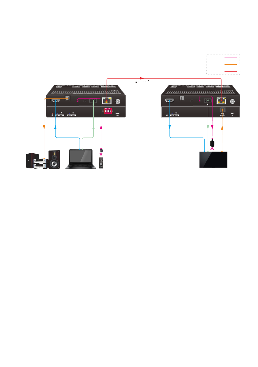
System Connection
The following diagram illustrates the typical input and output connections of the
extender:
1) The ARC mode of receiver is ON, and the display device (e.g. HDTV) supports
ARC. The TV audio is transmitted from the TV back to the receiver via HDMI
cable, and then it will be output by the ARC Audio Out port of transmitter.
Note: The STP cable is recommended to be used to ensure optimal machine
performance in ARC mode.
Tx Rx
LINKHDCP
1 2 3 4
Tx Rx
LINKHDCP
Speaker Laptop Remote HDTV
HDMI:
HDBaseT:
Audio:
IR:
RS232:
ARC
ARC
Tx Rx
IR
Receiver
PoC
4K 40m 1080P 70m,
IR
Emitter
10
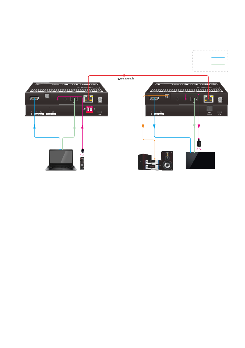
2) The ARC mode of receiver is ON, but the display device (e.g. HDTV) doesn’t
support ARC. The TV audio is transmitted from the TV back to the receiver via the
audio cable, and then it will be output by the ARC Audio Out port of transmitter.
Note: The STP cable is recommended to be used to ensure optimal machine
performance in ARC mode.
Tx Rx
LINKHDCP
1 2 3 4
Tx Rx
LINKHDCP
Speaker Laptop Remote HDTV
HDMI:
HDBaseT:
Audio:
IR:
RS232:
ARC
Tx Rx
ARC
IR
Receiver
PoC
4K 40m 1080P 70m,
IR
Emitter
11
3) The ARC mode of receiver is OFF. The TV audio can’t be back to the ARC Audio
Out port of transmitter. The Audio Breakout port of receiver is connected to
speaker or amplifier for HDMI source audio de-embedding.
Tx Rx
LINKHDCP
1 2 3 4
Tx Rx
LINKHDCP
Laptop Remote HDTV
Speaker
HDMI:
HDBaseT:
Audio:
IR:
RS232:
Tx Rx
IR
Receiver
PoC
4K 40m 1080P 70m,
IR
Emitter

12
Technical Specification
Transmitter
Receiver
Video
Input
(1) HDMI
(1) HDBT
Input Connector
(1) Type-A female HDMI
(1) RJ45
Input Resolution
Up to 4Kx2K@60Hz 4:4:4 8bit
HDR10
Up to 4Kx2K@60Hz 4:2:0
Output
(1) HDBT Out
(1) HDMI
Output Connector
(1) RJ45
(1) Type-A female HDMI
Output Resolution
Up to 4Kx2K@60Hz 4:2:0
Up to 4Kx2K@60Hz 4:4:4 8bit
HDR10
Audio
Input
-
(1) ARC Audio In
Input Connector
-
(1) Toslink Connector
Output
(1) ARC Audio Out
(1) Audio Breakout
Output Connector
(1) Toslink connector
(1) Toslink connector
Audio Format
Supports PCM, Dolby Digital, Dolby True-HD, DTS and DTS-HD.
Frequency Response
20Hz –20KHz, ±3dB
Max Output Level
2.0Vrms ±0.5dB. 2V = 16dB headroom above -10dBV (316mV)
nominal consumer line level signal
THD+N
< 0.05% (-80dB), 20Hz –20KHz bandwidth, 1KHz sine at 0dBFS level
(or max level)
SNR
> 85dB, 20Hz-20 kHz bandwidth
Crosstalk Isolation
> 70dB, 10KHz sine at 0dBFS level (or max level before clipping)
L-R Level Deviation
< 0.3dB, 1KHz sine at 0dBFS level (or max level before clipping)
Frequency Response
Deviation
< ±0.5dB 20Hz - 20KHz
Output Load Capability
1KΩ and higher (Supports 10x paralleled 10KΩ loads)
Stereo Channel
Separation
>70dB@1KHz
Control
Control Part
(1) Test Pattern button,
(1)1080P →4K button,
(1) EDID 4-pin DIP switch,
(1) FW, (1) IR In, (1) IR Out,
(1) RS232
(1) ARC Mode button, (1) FW,
(1) IR In, (1) IR Out, (1) RS232
Control Connector
(1) Micro-USB port,
(2) 3.5mm jacks,
(1) 3-pin terminal block
(1) Micro-USB port,
(2) 3.5mm jacks,
(1) 3-pin terminal block

13
General
Bandwidth
18Gbps
HDMI Standard
2.0
HDCP Version
2.2, 1.4 compliant
CEC
Pass-through
Bidirectional PoC
Supported
HDMI 2.0 Cable Length
4K@60Hz 4:4:4 ≤ 5m, 4K@60Hz 4:2:0 ≤ 15m, 1080P ≤ 20m
Transmission Standard
HDBaseT
Transmission Distance
1080P@60Hz ≤ 230 feet (70 meters),
4K@60Hz ≤ 131 feet (40 meters)
Operation Temperature
-5~ +55℃
Storage Temperature
-25 ~ +70℃
Relative Humidity
10%-90%
Power Supply
Input:100V~240V AC; Output:24V DC 1.25A
Power Consumption
12W (Max)
Dimension (W*H*D)
TX/RX: 140mm x 19.5mm x 84mm
Net Weight
TX:275g, RX:290g
Note: Please adopt high-qualified HDMI cable fully compliant with HDMI 2.0 for
reliable transmission and connection.
This manual suits for next models
2
Table of contents
Other Milestone pro Extender manuals

Milestone pro
Milestone pro MPTP-T60S-H2 User manual

Milestone pro
Milestone pro MPTP-TU50S User manual

Milestone pro
Milestone pro TP-T100A User manual

Milestone pro
Milestone pro MPHD-WL11 User manual

Milestone pro
Milestone pro MP-TP-T70S-H1 User manual

Milestone pro
Milestone pro MPTP-T100SS-H2 User manual

Milestone pro
Milestone pro MP-HDFB-4KT User manual


