milleteknik NOVA FLX M User manual
NOVA FLX M
NOVA 24V 15A FLX M, NOVA 24V 25A FLX M
EN

350-152
Publication date 2022-10-11

Table of Contents
1. Revisions and the edition of this document .......................................................................... 5
2. Variant overview NOVA ....................................................................................................... 5
3. Enclosures ........................................................................................................................ 6
3.1. Bracket ................................................................................................................... 6
3.2. Mounting on a wall or in a 19 "rack ........................................................................... 7
3.3. Mounting ................................................................................................................ 7
4. Component overviews ........................................................................................................ 7
4.1. Component overviewNOVA FLX M ........................................................................... 7
5. Batteries - placement and connection .................................................................................. 8
5.1. Placement of batteries ............................................................................................. 8
5.2. Connecting batteries in FLX M ................................................................................. 9
5.3. Connect battery fuse / blade fuse ........................................................................... 10
5.4. Connection of batteries in FLX S, FLX M and FLX L ................................................ 10
6. PCB description of PRO2v3 .............................................................................................. 11
6.1. Fuses ................................................................................................................... 12
6.2. Connect the mains to the motherboard (PCB) ......................................................... 12
6.2.1. Connect mains ........................................................................................... 12
6.3. Connect load ........................................................................................................ 13
6.4. Connection of load 15 A - 25 A units ....................................................................... 13
6.5. Load cards with blade fuses ................................................................................... 14
6.6. Alarm via communication ....................................................................................... 15
6.7. Communication to a parent system ......................................................................... 15
6.8. Configuration of communication via RS-485 ............................................................ 15
6.9. Dip switch 1-8 ....................................................................................................... 16
6.9.1. Address setting for external communication (Dip switch 1-4) .......................... 16
6.9.2. Mains failure delay (dip 5-6) ........................................................................ 16
6.9.3. Low battery level (dip 7) .............................................................................. 17
6.9.4. LED (dip 8) ................................................................................................ 17
6.9.5. Battery test (dip 8) ...................................................................................... 17
6.10. Reboot to confirm changes in address, battery and alarm settings to parent sys-
tem ............................................................................................................................. 18
6.11. Alarm card for PRO2 ........................................................................................... 18
7. Multiple units into one parent system ................................................................................. 19
8. Commissioning - how to start the unit ................................................................................ 20
8.1. 72 hours after commissioning / battery change ........................................................ 20
8.2. System test ........................................................................................................... 20
8.3. Recovery .............................................................................................................. 20
9. Alarm displayed on cabinet door ....................................................................................... 20
10. Adjustment of tamper switch ........................................................................................... 21
11. Maintenance .................................................................................................................. 22
11.1. About batteries .................................................................................................... 22
11.2. battery change .................................................................................................... 22
11.3. Battery recycling ................................................................................................. 23
12. NOVA product sheet ....................................................................................................... 24
12.1. SSF1014 certified battery backup with communication ........................................... 24
12.1.1. Name, article number, e-number and certificate number .............................. 24
12.1.2. About NOVA FLX ...................................................................................... 24
12.1.3. Area of use .............................................................................................. 25
12.1.4. Installation video ....................................................................................... 25
12.2. Regulations and certifications ............................................................................... 25
12.2.1. Standards that product (s) meet and are approved for ................................. 25
12.2.2. Requirements that the product meets ......................................................... 26
12.3. Spare operating times, power outlet and load output power .................................... 26
3

12.3.1. Charging current for batteries and battery capacity ..................................... 26
12.3.2. Power outlet NOVA FLX ............................................................................ 27
12.3.3. Power outlet ............................................................................................. 27
12.3.4. Permitted average load according to SSF1014 Alarm class 1-4: .................. 28
12.3.5. Reserve operating times for different alarm classes - overview .................... 28
12.4. Circuit boards - Technical data ............................................................................. 28
12.4.1. Technical data, motherboard: PRO 2 V3 ..................................................... 28
12.4.2. Technical data, alarm cards for PRO 2 and PRO2 V3 .................................. 29
12.5. Power supply ...................................................................................................... 30
12.5.1. Power supply - Technical Data RSP-320-24 ................................................ 30
12.5.2. Power supply - Technical Data HRP-600-24 ............................................... 31
12.6. Technical data enclosures .................................................................................... 31
12.6.1. Enclosures - Technical Data FLX M ........................................................... 31
12.7. Link to the latest information ................................................................................. 32
12.8. Warranty, support, country of manufacture and country of origin ............................. 32
12.8.1. Warranty 5 years ...................................................................................... 32
12.8.2. Manufacturer support ................................................................................ 32
12.8.3. Support .................................................................................................... 32
12.8.4. Contact us ................................................................................................ 33
12.8.5. Country of manufacture ............................................................................. 33
12.8.6. Designed and produced by: Milleteknik AB ................................................. 33
12.9. Product life cycle, environmental impact and recycling ........................................... 33
12.10. Batteries - recommended, not included ............................................................... 33
12.10.1. Batteries are not included they are sold separately .................................... 33
12.10.2. Battery combinations NOVA FLX M .......................................................... 33
12.10.3. Certified with battery type ........................................................................ 34
12.10.4. 20 Ah, 12 V AGM battery ......................................................................... 34
12.10.5. Reserve operating times for different alarm classes - overview ................... 34
13. Connection of battery box ............................................................................................... 36
13.1. Installation of battery box, what to do in battery backup .......................................... 36
13.2. Connection of batteries battery box ...................................................................... 37
13.3. Connection of battery box NOVA FLX with battery backup NOVA FLX ..................... 38
13.4. Wiring diagram and jumper .................................................................................. 39
13.5. Battery backup (NOVA FLX) with 4 battery boxes (NOVA FLX) ............................... 40
13.6. Tamper switch when using battery box(-es) ........................................................... 40
14. Address and contact details ............................................................................................ 40
4

1. REVISIONS AND THE EDITION OF THIS DOCUMENT
The current and most recently published edition of this document is available at www.milleteknik.se.
The validity of this document can not be guaranteed, as new editions are published without prior notice.
READ THIS FIRST!
Electronics, regardless of enclosure, are intended for use in a controlled indoor envi-
ronment.
Ventilation must not be covered.
Only authorized persons should install and maintain the system.
It is the installer's responsibility to ensure that the system is suitable for its intended
use.
Documents accompanying the system must be kept in or in its immediate vicinity.
Mains voltage should be disconnected during installation.
All information subject to change.
Upon installation of this product, the installer acknowledges and accepts the limitations
of this product as described in this manual.
ABOUT GLASS TUBE FUSES ON CERTIFIED
DEVICES
There are glass tube fuses on the circuit board's load outputs, these
have a tripping time of approx. 150 ms. In the event that a glass tube
fuse trips on ONE load output, the voltage on ALL load outputs drops
to 0 V for 150 ms.
The installer is responsible for ensuring that there is an energy buffer
of at least 150 ms in systems that the battery backup supplies power
to or accepts a power failure of 150 ms.
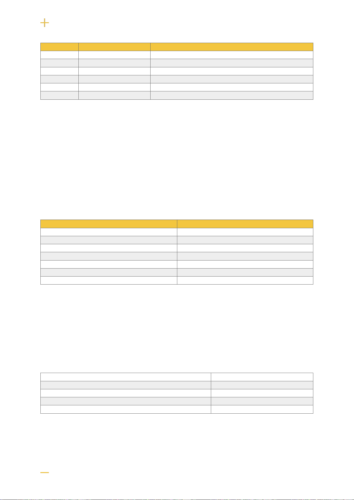
2. VARIANT OVERVIEW NOVA
Table 1. Variant overview
Product name Certified name Mother-
board:
PRO1
Mother-
board
PRO2:
Mother-
board
PRO2 v3
Mother-
board:
PRO3
NOVA 12V 10A FLX S 12 V meets the requirements but
is not certified. - - - x
5

Product name Certified name Mother-
board:
PRO1
Mother-
board
PRO2:
Mother-
board
PRO2 v3
Mother-
board:
PRO3
NOVA 12V 10A FLX M - - - x
NOVA 12V 10A FLX L - - - x
NOVA 24V 5A FLX S NOVA 25 50-FLX-S X X - X
NOVA 24V 10A FLX S NOVA 25 100-FLX-S X X - X
NOVA 24V 5A FLX M NOVA 25 50-FLX-M X X - X
NOVA 24V 10A FLX M NOVA 25 100-FLX-M X X - X
NOVA 24V 15A FLX M NOVA 25 150-FLX-M X X X -
NOVA 24V 25A FLX M NOVA 25 250-FLX-M X X X -
NOVA 24V 5A FLX L NOVA 25 50-FLX-L X X - X
NOVA 24V 10A FLX L NOVA 25 100-FLX-L X X - X
NOVA 24V 15A FLX L NOVA 25 150-FLX-L X X X -
NOVA 24V 25A FLX L NOVA 27 250-FLX-L X X X -
3. ENCLOSURES
3.1. Bracket
Brackets are used so that the unit can be mounted on a wall or in a 19 "rack.
Nr Explanation
1 Clip in bracket that secures the bracket to the housing.
2 Holes for screws - can be used to secure the bracket in the housing.
3 The brackets is screwed to a wall or 19 "rack.
6
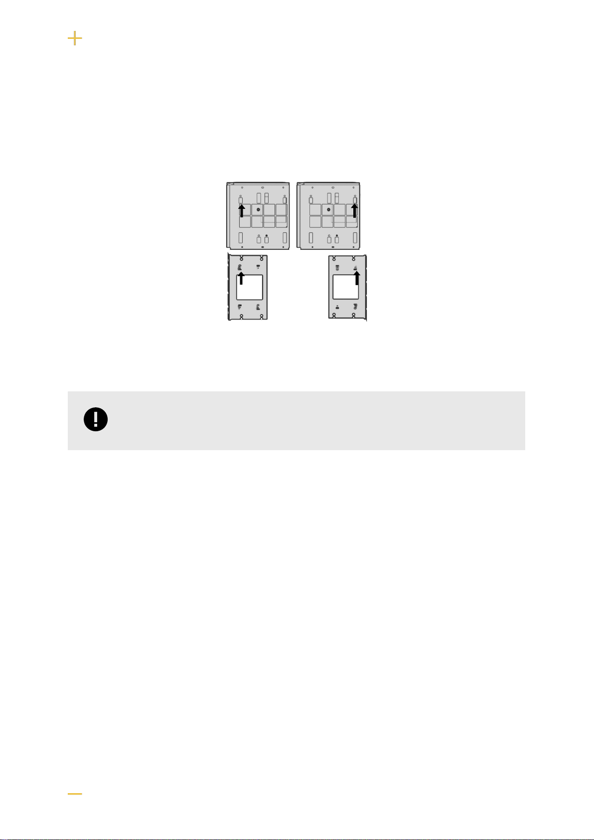
3.2. Mounting on a wall or in a 19 "rack
The unit can be mounted in a 19 ”rack or on a wall. The included brackets can be attached in two
ways: When mounting on a wall, the brackets must sit backwards, against the wall. When mounting in a
19 ”rack, the console must be at the front edge of the unit.
Figure 1. FLX M - mount brackets
Left bracket facing the front for mounting in a 19 "rack.
Right bracket facing the back for wall mounting.
IMPORTANT
Leave 100 mm free around the air vents.
3.3. Mounting
Use the appropriate screw for mounting on a wall or in a 19" rack. Screws for mounting on a wall or in a
rack are not included.
4. COMPONENT OVERVIEWS
4.1. Component overviewNOVA FLX M
7
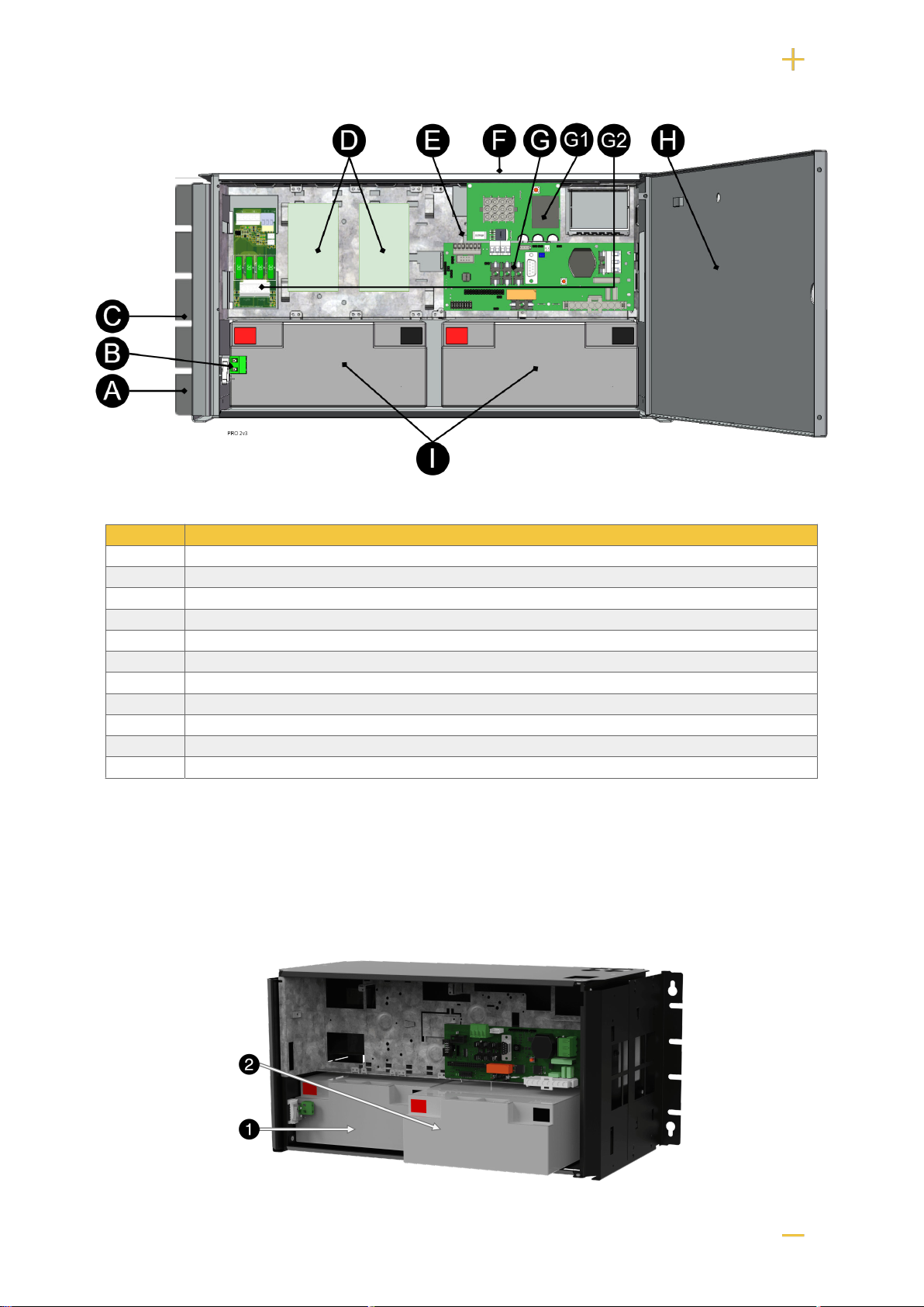
Table 2. Component overview
Letter Explanation
A Bracket, reversible for wall mounting or 19 "rack.
B Sabotage contact. If alarm class 3 (SSF) is to be met, the tamper switch must be on the wall.
C Cabinet in powder-coated sheet metal.
D Load card - load is connected here.
E Power supply.
F Cable entries.
G Motherboard.
G1 Effect card.
G2 Load card.
H Lockable door.
I Space for batteries.
5. BATTERIES - PLACEMENT AND CONNECTION
5.1. Placement of batteries
8

5.2. Connecting batteries in FLX M
Figure 2. Connection of batteries in FLX M. Motherboards may differ depending on the configuration, but connection of batteries takes
place in the same way.
Note that cards (4) differ from different configurations.
Nr Explanation
1 Minus coil for battery cable from 4.
2 Fuse.
3 Plus terminal for battery cable from 4.
4 Motherboard, varies with configuration.
5 Battery cables are located on the system board.
6 Yellow cable, which must be cut when connecting the battery box.
7 Connection for connection of battery box.
8 Alarm cable for battery box.
9 Cable for tampering in battery box.
9
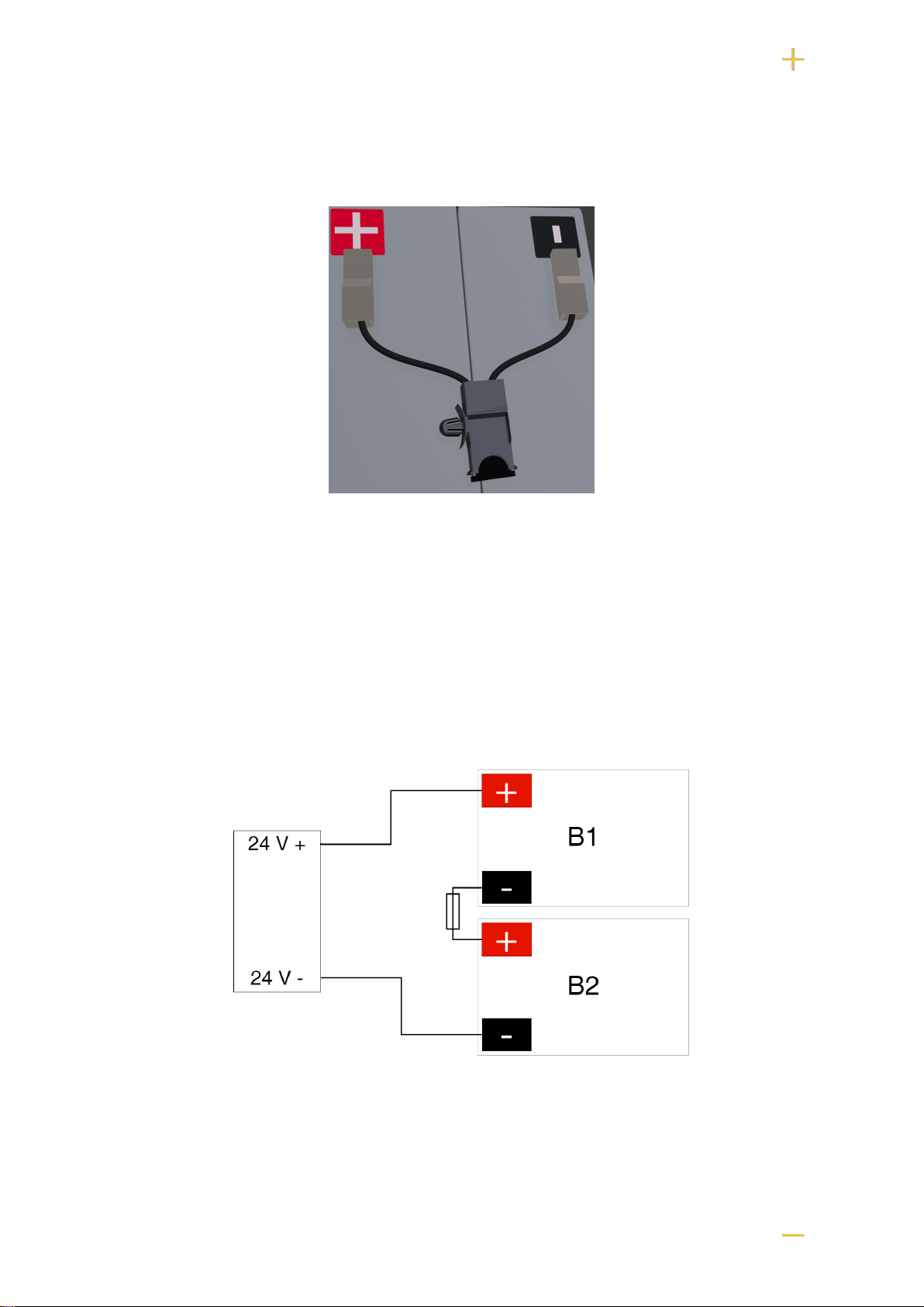
5.3. Connect battery fuse / blade fuse
Figure 3. Fuse holders with blade fuses are connected to + and minus on batteries
5.4. Connection of batteries in FLX S, FLX M and FLX L
Battery wiring is mounted on the circuit board upon delivery. Pictures below only show how to connect
wiring.
1. Place the batteries in the cabinet with the battery terminals facing outwards.
2. Connect the battery cable. Red cable on + and black cable on -.
• If possible, disconnect mains voltage when replacing the battery.
Figure 4. Wiring diagram for batteries in battery backup
Connect the terminals correctly so that you do not damage the equipment.
10
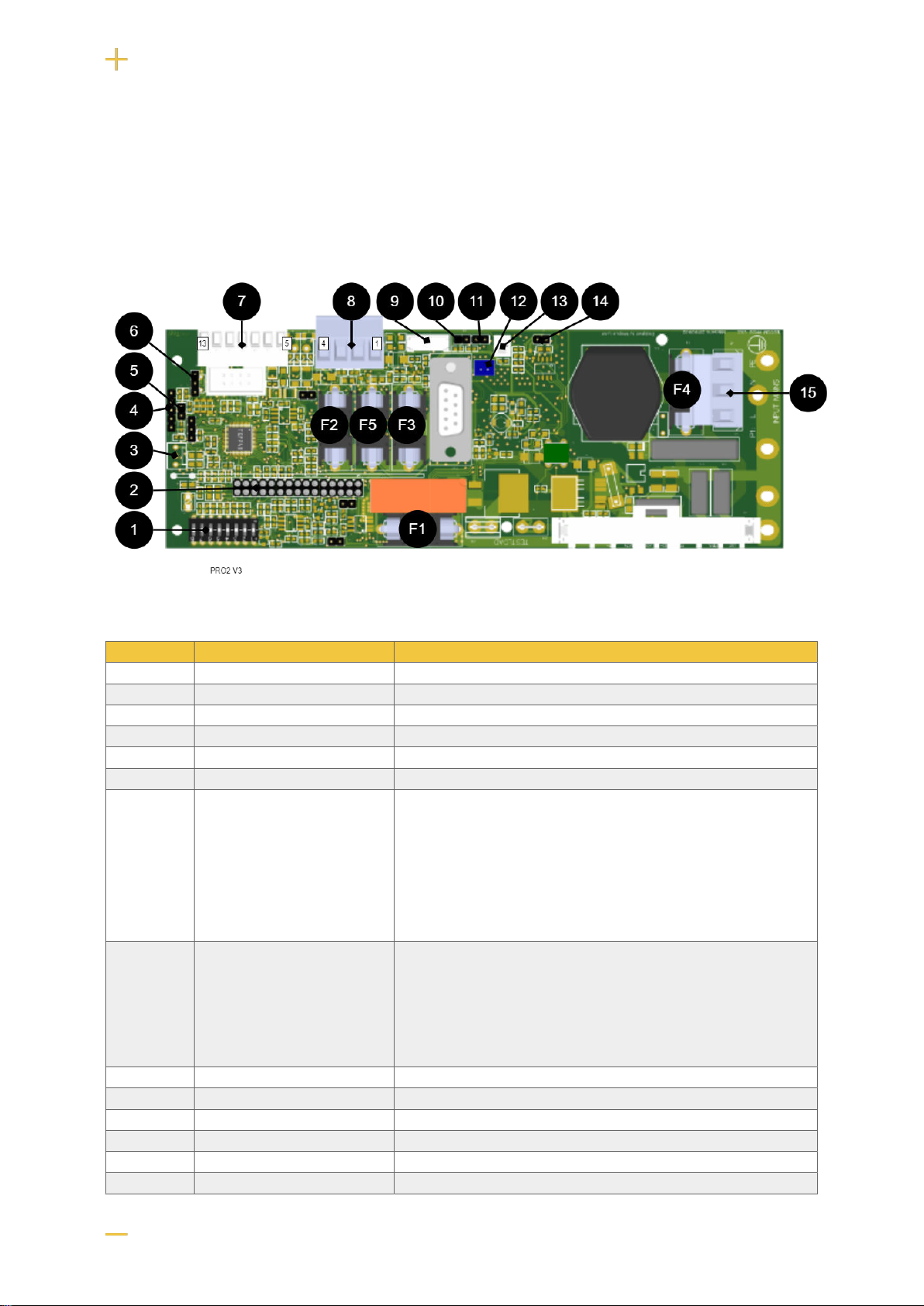
6. PCB DESCRIPTION OF PRO2V3
The motherboard controls the device, distributes power and communicates with other systems. See
technical data for more information.
Figure 5. PRO2 v3
Table 3. Circuit board overview, explanation
No . On circuit board Explanation
1 Dip SW Dip switch 1-8
2 J20 Connection relay board.
3 JU17 Connection external indicator diode.
4 - Programming contact.
5 J13 Reset of data after battery replacement.
6 J6 Temperature sensor.
7 P2:7-13
7-8
9-10
11
12
13
Connection communication.
RS-485
GND, Protective earth
RX
TX
+5V
8 P2:1-4
1
2
3
4
Load outputs.
+
-
+
-
9 J29 Connection to fan.
10 J14 Tamper switch connection.
11 J3 Connection tamper switch from battery box.
12 J1 Connection option card.
13 J4 Connection external fuse (NO).
14 J7/21 Connection to external fuse (NC).
11
No . On circuit board Explanation
15 P1:1-3 Incoming mains, (230 V). L, N, PE.
6.1. Fuses
Table 4. Fuses on PRO2 / PRO2 V3
Fuse Type Explanation
F1 T16A Mains fuse
F2 T2A Load fuse 2 + (for P2: 4)
F3 T2A Reading protection 1 + (for P2: 1)
F4 T2.5A / T4A Mains fuse, the lower valute for units 5 A - 15 A and the higher value for 25 A units.
F5 T16A Load fuse 1+ (for P2: 2)
FUSE REPLACEMENT WARNING (A)
There is a risk of damage if the fuse is changed to a larger one than what the unit
is delivered with. The function of the fuse is to protect the connected load and cables
against damage and fire. It is not possible to change the fuse to a larger one to
increase the power output.
6.2. Connect the mains to the motherboard (PCB)
6.2.1. Connect mains
Pull wiring through the cable entry on the cabinet.
If possible, secure the mains cable with cable ties where possible.
Electrical network cabling shall be kept separate from other cabling to avoid EMC interference.
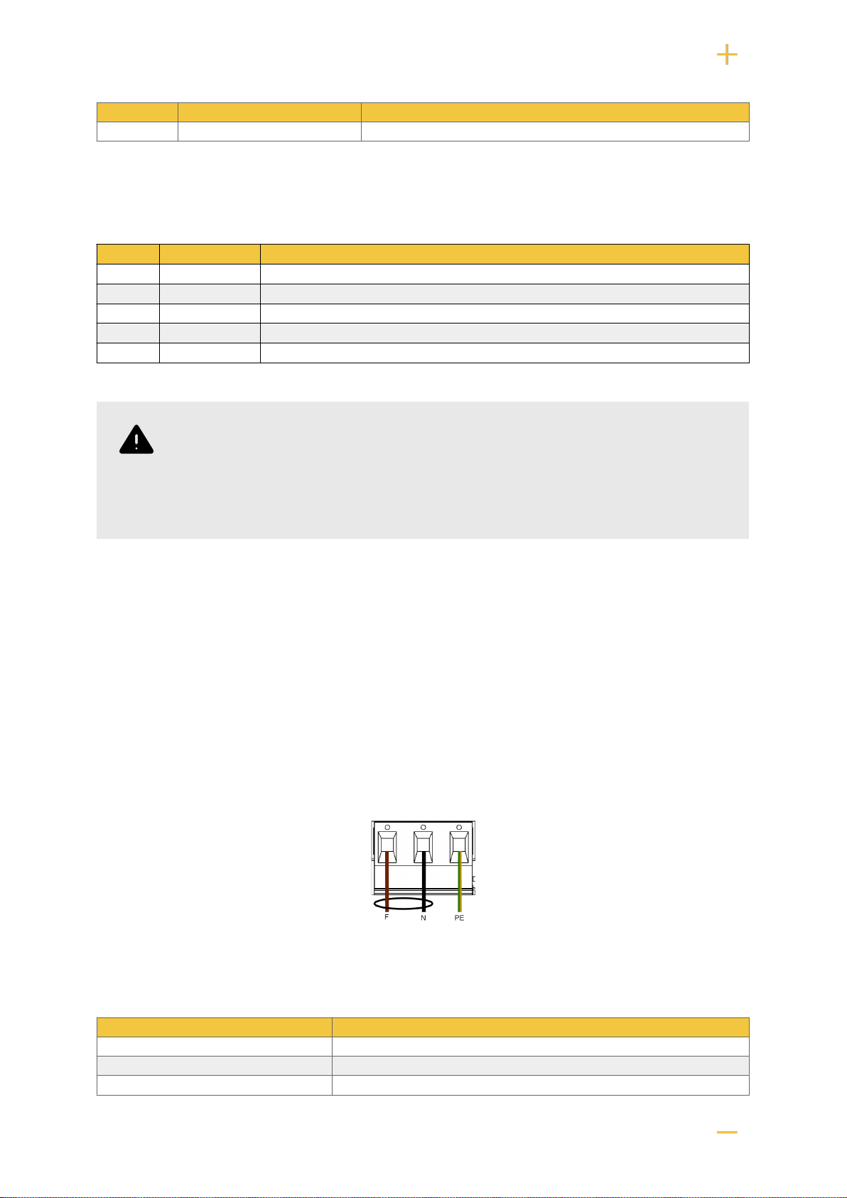
Figure 6. Connect the mains to the motherboard
Connect the mains cable to the terminal before it is put back on the motherboard. Secure F and N with
cable ties for electrical safety.
Table 5. Electrical network connections
Letter Explanation
F Phase
N Neutral
PE Protective earth
12
ELECTRICAL MAINS CONNECTION 230 V AC ON CIRCUIT
BOARD
Check that the marking on the circuit board matches the cable arrangement on the
terminal block.
6.3. Connect load
MAX CURRENT
Maximum current must not be exceeded. Maximum current is indicated on the CE-
marking on the unit.
LOAD OUTPUTS WHEN SSF CERTIFIED
In order for certificates to be maintained, only one load output must be used.
If there are one or more connection cards (to increase the number of load outputs), load must be
connected there and not on the main board.
Table 6. Load connections
Circuit board number Explanation
P2: 1 Connection for load 1 +
P2: 2 Connection for load 1 -
P2: 3 Connection for load 2 -
P2: 4 Connection for load 2 +
CAUTION
Load may only be connected to the motherboard in 5 A and 10 A units. For other units,
load must be connected via power board or option board.
6.4. Connection of load 15 A - 25 A units
For units with a effect card, which is available to handle the higher currents (15 ampere and above), the
load must be connected on an optional board.
See documentation for option board for how to connect load.
13
WARNING
Load must not be connected to the motherboard if the device is a 15 A or 25 A, as it
will be destroyed during commissioning. Motherboards that are faulty due to incorrect
connections are not covered by warranty.
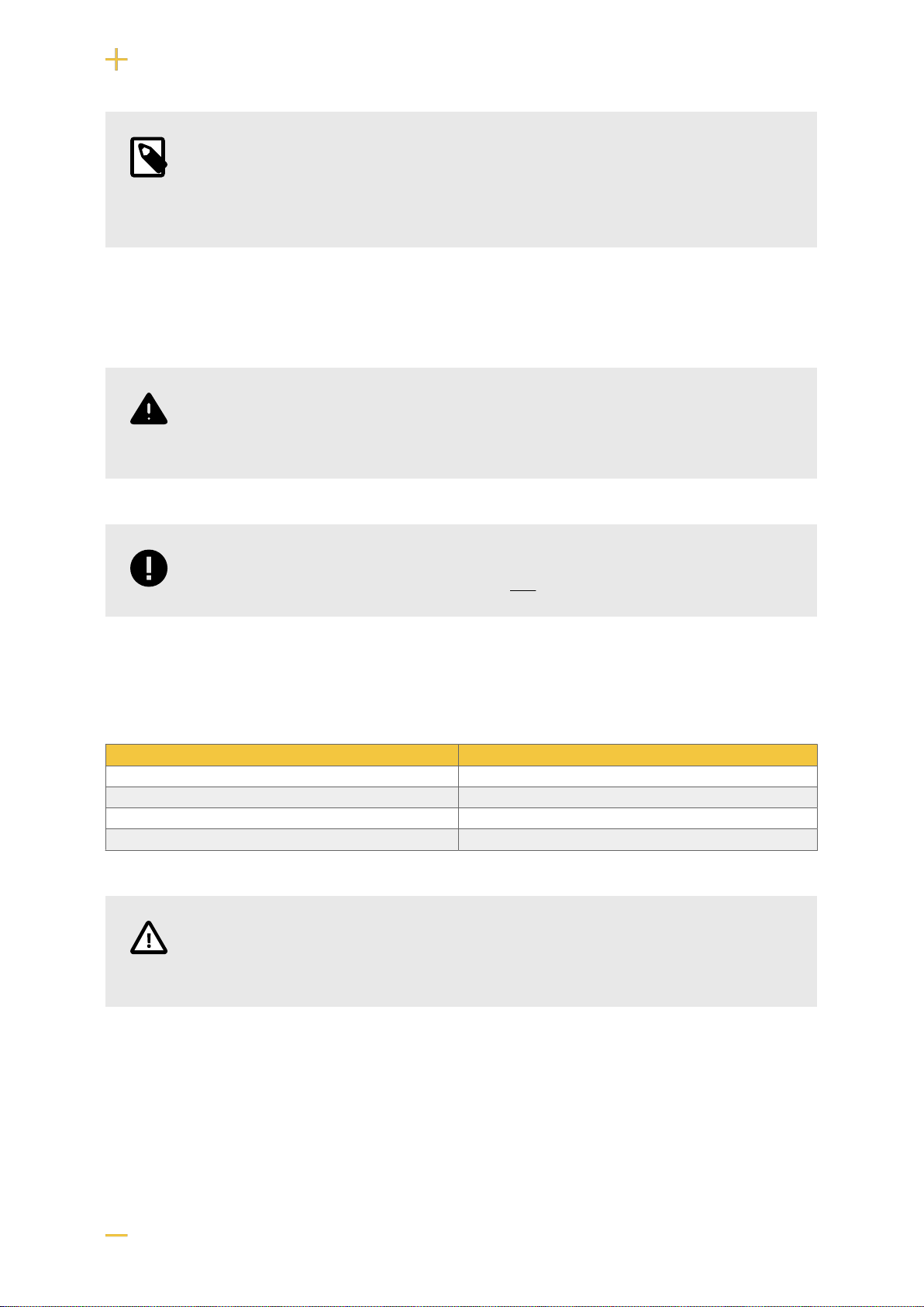
Figure 7. Effect card
The effect card increases the current for 15 A and 25 A units.
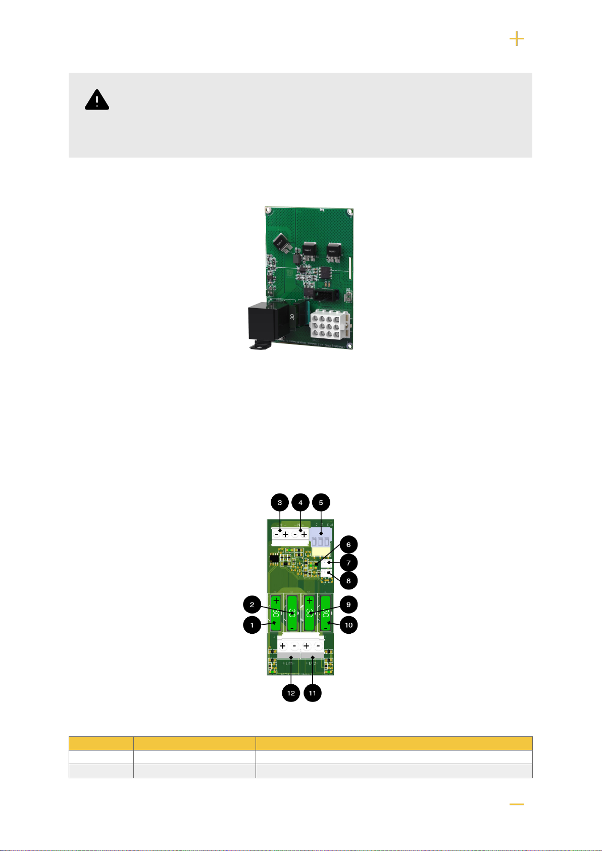
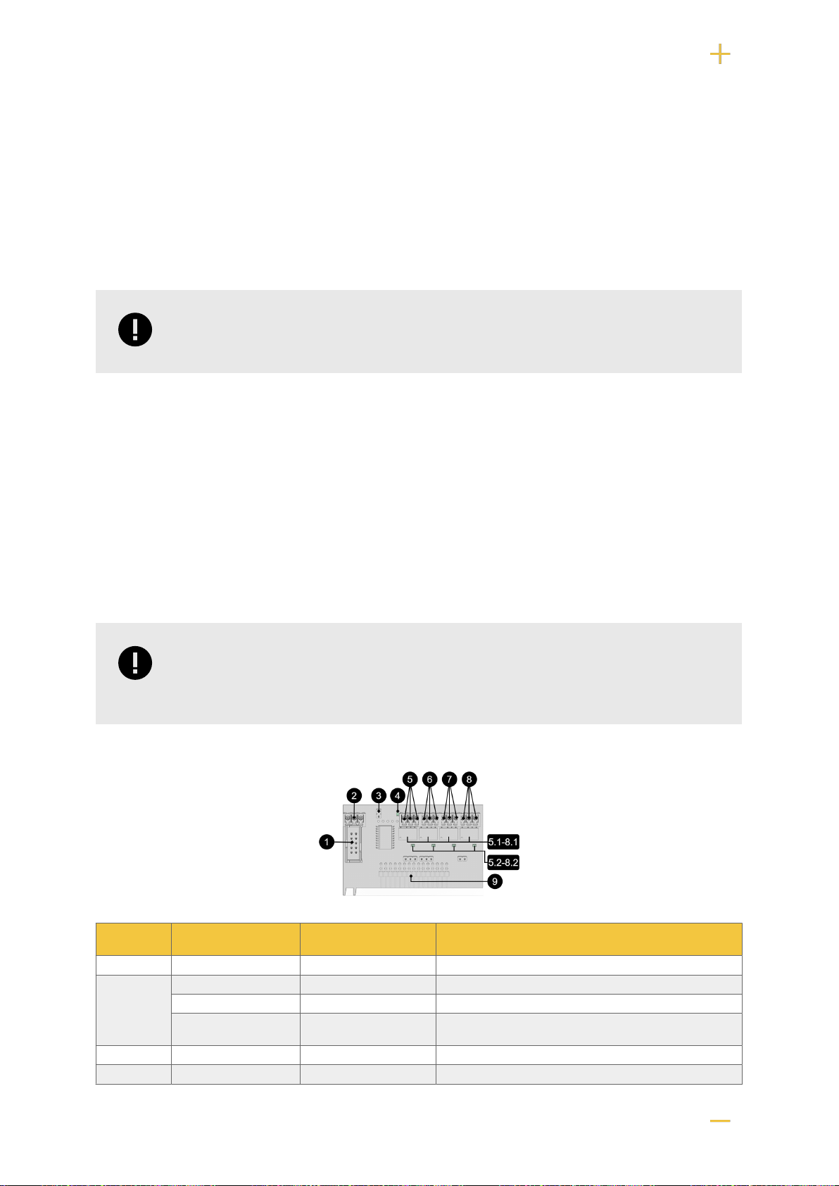
6.5. Load cards with blade fuses
The card replaces the load output on the motherboard.
The load card has a different type of fuse that is easier to change and at the same time the card
provides a easier connection of the load.
Table 7. Circuit board overview, explanation
No . On circuit board Explanation
1, 9 FUS2, FUS4 + fuse, 10 A- 25 A depending on the product.
2, 10 FUS1, FUS3 - fuse, 30A.
14
No . On circuit board Explanation
3, 4 IN1, IN2 Incoming connection 24 V, (from motherboard).
5 P1:1-3 Alarm relay: NC, Com, NO
6 D29, D30 LED.
7 J1 Fuse alarm.
8 J2 Fuse alarm for forwarding to several cards.
11, 12 +UT1-, +UT2- Load connection, outgoing, 24 V
Load is connected to 11 or 12 on fuse card, see component overview.
6.6. Alarm via communication
Connection of communication to the parent system takes place via JU6. See the parent system docu-
mentation for more information.
6.7. Communication to a parent system
It is possible to connect communication to a parent system via connections on P2: 5-13. See also
parent system documentation for compatible protocol. For more information on alarms; see ???.
Table 8. Connections over communication
Terminal block Explanation
P2: 7 RS-485 -
P2: 8 RS-485 +
P2: 9 System minus -
P2: 10 System-minus -
P2: 11 RXD
P2: 12 TXD
P2: 13 +5 V
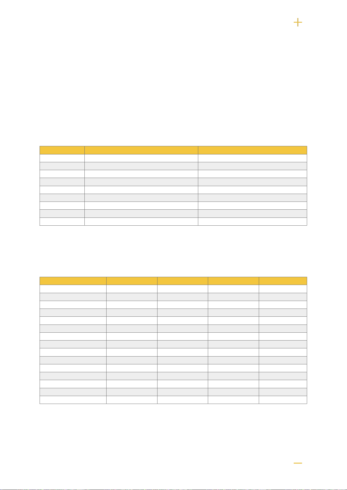
6.8. Configuration of communication via RS-485
Communication via RS-485 is connected to P2: 7- & P2: 8+.
The address is set binary on the switch.
ADDRESS configuration:
Table 9. S1 Dip switch
Dip switch Value
Dip switch 1= 1
Dip switch 2= 2
Dip switch 3= 4
Dip switch 4= 8
If all dip switches are set to OFF, the address is 0+0+0+0=0.
If dip-switch 1 and 3 are ON, the address is 1+0+4+0= 5.
If dip-switch 2 and 4 are ON, the address is 0+2+0+8=10.
15
For Sentrion only: addresses in Sentrion add +1. This means that 1 must always be added to the
configuration.
If all dip switches are set to OFF, the address is 0+0+0+0(+1*)=0 (1*).
If dip-switch 1 and 3 are ON, the address is 1+0+4+0(+1*)= 5(6*).
If dip-switch 2 and 4 are ON, the address is 0+2+0+8(+1*)=10(11*).
6.9. Dip switch 1-8
Dip-Switch has several different configuration modes:
Table 10. Dip switch 1-8
Dip switch In mains operation or in battery operation Comment
1-4 Address for external communication. -
2 Address for external communication -
3 Address for external communication -
4 Address for external communication -
5 Sets alarm for mains failure delay Available from software v1.5
6 Sets alarm for mains failure delay Available from software v 1.5
7 Sets alarm for low battery level. Available from software v 1.5
8 Turns LED off or on. Upcoming feature through software update
8 in sequence Performs battery test Not available in NEO.
6.9.1. Address setting for external communication (Dip switch 1-4)
Dip-Switch S1: 1-4 sets addressing.
Table 11. Addressing Dip-Switch 1-4
Dip: 1 Dip: 2 Dip: 3 Dip:4
Adress 1 ON OFF OFF OFF
Adress 2 OFF ON OFF OFF
Adress 3 ON ON OFF OFF
Adress 4 OFF OFF ON OFF
Adress 5 ON OFF ON OFF
Adress 6 OFF ON ON OFF
Adress 7 ON ON ON OFF
Adress 8 OFF OFF OFF ON
Adress 9 ON OFF OFF ON
Adress 10 OFF ON OFF ON
Adress 11 ON ON OFF ON
Adress 12 OFF OFF ON ON
Adress 13 ON OFF ON ON
Adress 14 OFF ON ON ON
Adress 15 ON ON ON ON
6.9.2. Mains failure delay (dip 5-6)
It is possible to change the time for when the alarm for a power outage should be given. Use the matrix
to set the alarm.
16
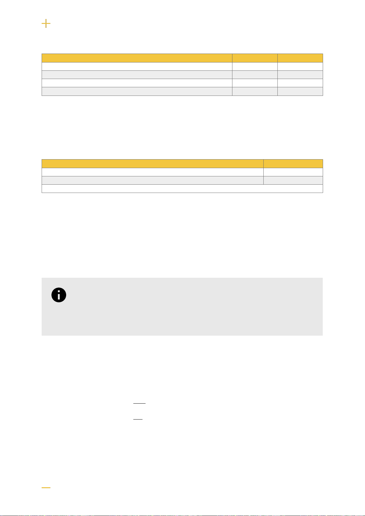
Table 12. Mains failure delay
Alarms for mains failure are given after: Dip 5 Dip 6
10 seconds OFF OFF
30 minutes OFF ON
60 minutes ON OFF
240 minutes (4 hours) ON ON
6.9.3. Low battery level (dip 7)
Dip: 7 has the same function regardless of whether the unit is in mains or battery operation or whether
the tamper switch is held down.
Table 13. Low battery level
Alarm for low battery level is given Dip 7
22,8 V* ON
24 V OFF
*25% of battery capacity remains.
6.9.4. LED (dip 8)
LED/battery-test always lights up when the door is open.
Dip-switch 8=ON turns off the LED.
Dip-switch 8=OFF turns on the LED.
NOTICE
For certified units:
To comply with SSF-1014 up to alarm class 4, the LED on the door must be off
(Dip-switch 8 to ON).
6.9.5. Battery test (dip 8)
To do a battery test, dip 8 needs to change position and five seconds need to pass before the test is
initiated.
• If dip 8 in original position is on OFF then switch dip 8 to: ON (wait 5 seconds) and then switch back
to OFF.
• If dip 8 in original position is on ON then switch dip 8 to: OFF (wait 5 seconds) and then switch back
to ON.
This activates the battery test after 3-8 seconds. The battery test lasts for about 6 seconds and then
the LED flashes yellow quickly. Aged battery alarms may be indicated while the battery test is being
performed.
Only reset dip 8 when the test is complete.
17
6.10. Reboot to confirm changes in address, battery and alarm set-
tings to parent system
After the dip-switch has been set for various parameters, the device's software needs to be restarted.
This is for the new settings to be stored and take effect.
Restarting the device software is done by jumpering J13 (PRO2)
IMPORTANT
Reboot must be done every time a change is made to the device.
6.11. Alarm card for PRO2
Relay card - description, connections and alarm outputs.
• All fault arm relays must be in the drawn state. Check that there is a gap between CO and NC. Put
the measuring instrument on continuity measurement and test closure. This should then indicate a
short circuit.
• All relay outputs are normally live and give an alarm in the event of no voltage.
IMPORTANT
There is normally a 10 second delay in alarm reset. The software on the main board
must be configured for a different time period.
No . Relay (Terminal no.) The relay is normally
energized. Alarm type / explanation
1 J7 - Connection for RS-232 cable.
2 P4:1 - RS-232: TxD, data OUT from motherboard.
P4:2 - RS-232: RxD, data IN to motherboard.
P4:3 - RS-232: Ground, do not connect ground to another termi-
nal.
3 J6 - Reset jumper.
4 D7 - Indicator diode, flashes green during normal operation.
18
No . Relay (Terminal no.) The relay is normally
energized. Alarm type / explanation
5,5.1, 5.2 P5:1-3 NO, COM, NC Tamper alarm, (optional for EN54). 5.1 Relay. 5.2 LED,
lights up green when relay is energized.
6, 6.1, 6.2 P5:4-6 NO, COM, NC Alarm for: Low system voltage. 6.1 Relay. 6.2 LED, lights
up green when relay is energized.
7, 7.1, 7.2 P5:7-9 NO, COM, NC Alarm for: Fuse failure, charger failure overvoltage, charger
failure undervoltage, cell failure/not connected battery, low
battery voltage in case of mains failure and aged battery.
7.1 Relay. 7.2 LED, lights up green when relay is energized.
8, 8.1, 8.2 P5:10-12 NO, COM, NC Power failure alarm. 8.1 Relay. 8.2 LED, lights up green
when relay is energized.
9 J11 - Connection to motherboard.
Via communication on PRO1 card: All alarms and alarms for: Fan fault, overtemperature, subtemperature, short battery life left,
overcurrent 100% of minute average, overcurrent 80% daily average and overcurrent 175% second average.
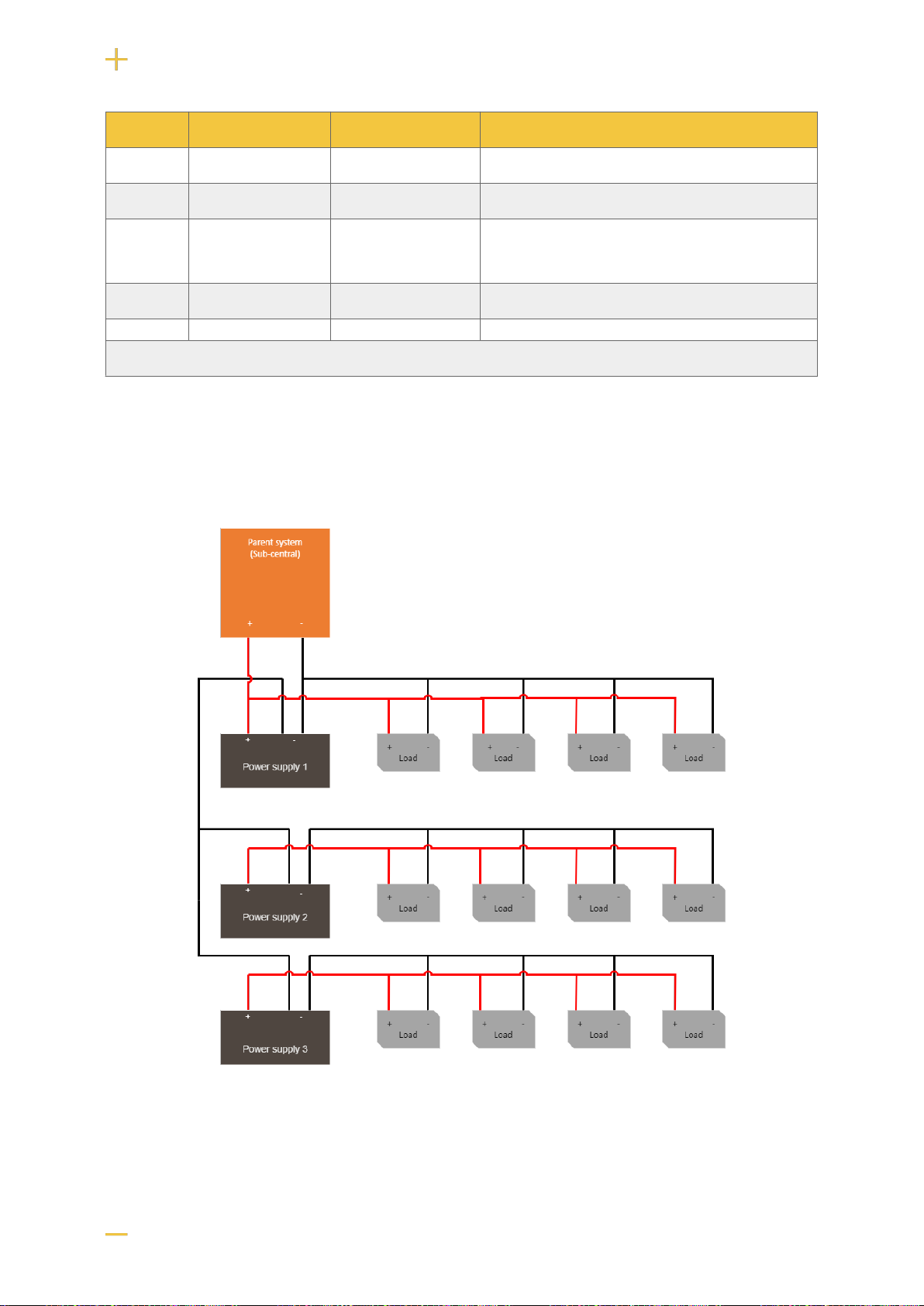
7. MULTIPLE UNITS INTO ONE PARENT SYSTEM
To connect several units to a parent system, load-minus (P2: 2, P2: 4) must be connected.
19

8. COMMISSIONING - HOW TO START THE UNIT
1. Connect batteries
2. Connect / switch on fuses
3. connect load, alarm and possibly. other connections.
4. Screw the mains cable into the terminal block and attach the terminal block to the motherboard.
5. Switch on mains voltage.
The unit works normally when the indicator LED on the outside of the cabinet door lights up with a solid
green light. See front panel for other status indications.
It may take up to 72 hours before the batteries are fully charged.
8.1. 72 hours after commissioning / battery change
For the first 72 hours after commissioning, the device does not perform a battery capacity test. The test
is postponed so that the device does not falsely alarm before the batteries are charged. The unit must
always be started with new batteries when commissioning or changing batteries and it is unlikely that
new batteries are faulty.
8.2. System test
Test the connected device by performing a system test afterwards commissioning [20].
• Switch on incoming mains voltage.
• Indicator LED on the outside of the cabinet door lights up with a solid green light. Disconnect the
mains voltage to check that the unit is operating in battery mode and alarms.
• Indicator LED on the cabinet door flashes, see alarm type panel.
• Switch on incoming mains voltage. Indicator LED, on the outside of the cabinet door, lights up with a
solid green light. Normal operation.
8.3. Recovery
Reset the unit by completely de-energizing the unit.
Disconnect battery wiring and mains voltage and reconnect after 5 seconds.
9. ALARM DISPLAYED ON CABINET DOOR
In normal mode, the indicator LED shows a solid green light.
20
Other manuals for NOVA FLX M
1
This manual suits for next models
24
Table of contents
Other milleteknik Power Supply manuals


Popular Power Supply manuals by other brands

Helios Power Solutions
Helios Power Solutions TDK-Lambda PFE700SA Series instruction manual

Gallagher
Gallagher M550 instructions

BCP
BCP PUOOUBZ How to install

Spellman
Spellman uX50P50 instruction manual

Elmdene
Elmdene 2401ST quick start guide

Cross Technologies
Cross Technologies 2000-2 LNB Series instruction manual


