Mills C00-6435 User manual

C00-6435
millsltd.com

WARNINGWARNING
You arecautioned that changesor modifications not espressly approved in
this document could voidyout authority to operatethis equipment.
To reducethe risk of fireor electric shock,do notexpose this apparatus to
rain or moisture.
Toavoid electrical shock, do not openthe cabinet. Refer servicing to quali-
fied personnel only.
NOTENOTE
As the laser isharmful to the eyes,do not attempt todisassemble the cabinet.
Avoiding condensation problems
As much aspossible, avoid sudden temperature changes. Donot attempt
to use thedrive immediately after moving it froma cold to a warm location,
to raising the roomtemperature suddenly,as condensation may formwith
in the drive.If the temperature changes suddenly whileusing the drive,
stop using itand take out batteries for atleast an hour.
Storage
When long timeno use,must take out the batteriesto avoid destroying the
device.
Use batteries
At the same time, can not usedifferent style ordifferent capacitance batteries.
And only charge therechargeable batteries.
1

2
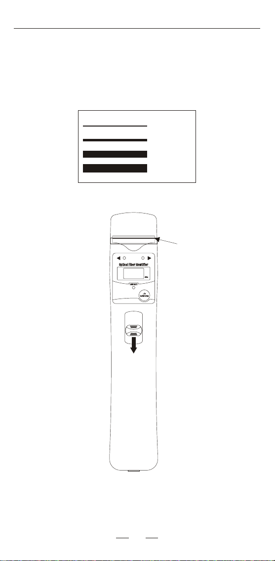
Description
1-Fiber location
2-Left indicative led
3-Power key ofvisual fault locatorand optical powermeter
4-Trigger of the fiber identifier
5-Right indicative led
6-Power indicative led
7-Calibration button
8-Connector of OPM/VFL( optional )
8
1
3
4
25
6
7
3
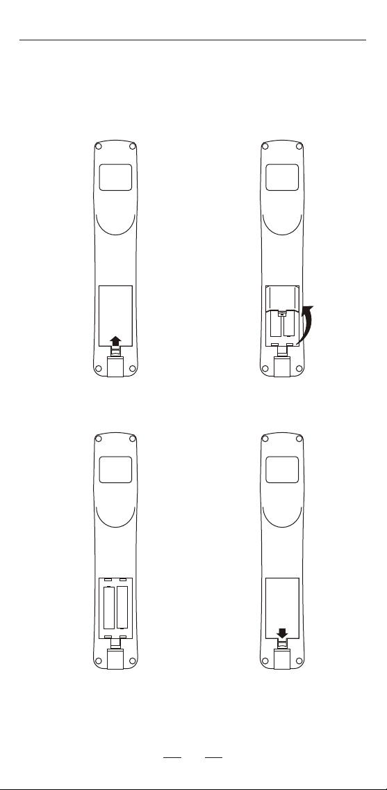
Battery set
Warning:At the sametime, can not usedifferent style and different capacitance batteries.
1.Push the tip 2.Open the batteryslot
3.Replace the batteries 4.Close the batteryslot
4
Silver indicative line
Availabe for dierent Fiber
1.Available for 800nm~1700nm laser signal
2Based on non-destructive technology
3No need to replace the clamp block for different ber
.
.
Availabe for dierent Fiber
250um bare ber
900um ber
2.5mm patch cord
3mm patch cord
When testing 2.5mm and 3.5mm patch cord, the silver
indicative line needsto be seen to ensure a correct
measurement
5
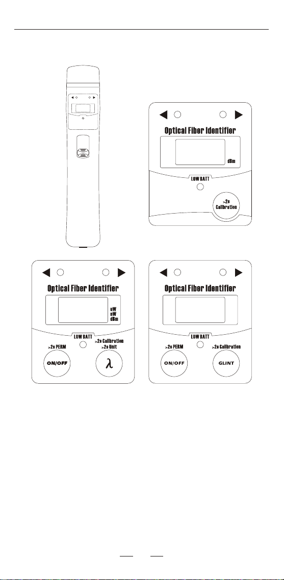
Fiber Identification models
LOWBATT
a.standard Optical Fiber
Identfier
b.Optical Fiber Identifier
with OPM mode
c.Optical Fiber Identifier
with VFL mode
AFI430 serialhas three models,include standard Optical
Fiber Identifier,Optical Fiber Identifierwith OPM modeand
Optical Fiber Identifierwith VFL mode. Different models with
different buttons, which shown inthe pictures above.
>2s SAVE
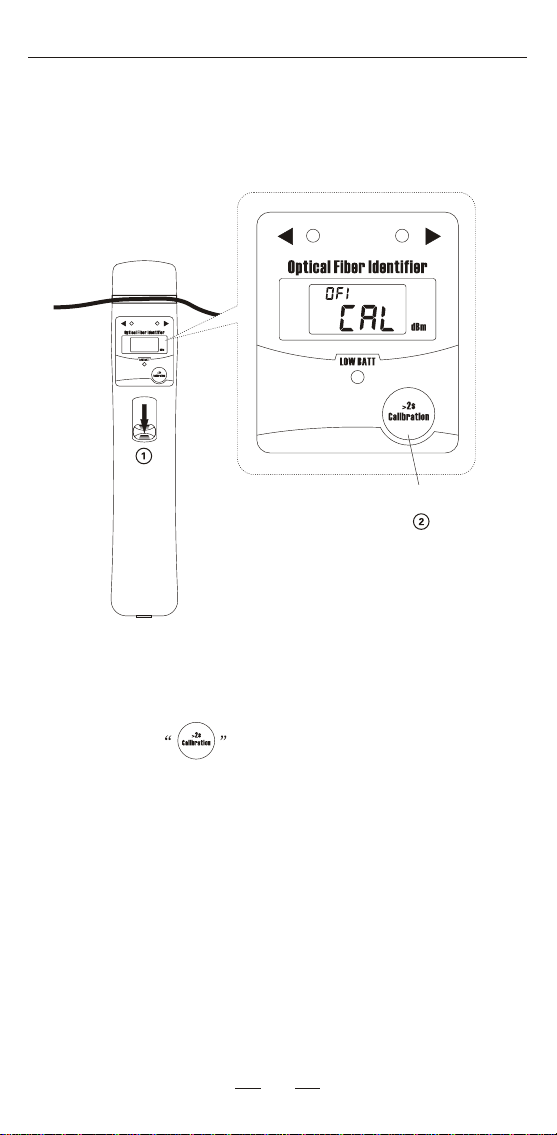
Environment Light Calibration
6
Calibration button
Push down the trigger of the ber identier and hold, then
long press the button. Until the unit beeps and the
the screen shows "CAL", the environment light calibration is
nished.
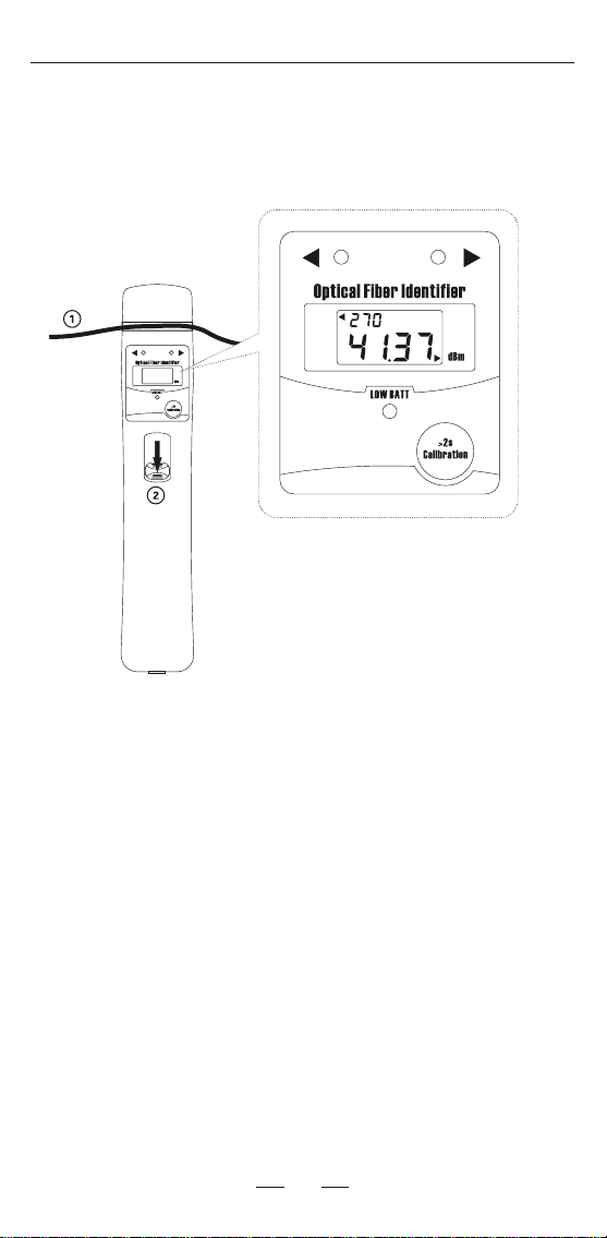
Operation
7
Put the ber into the ber location and push down the
trigger to begin testing. After 1~3 seconds, it will output the
results.
The data in the LCD shows the signal intensity, if the
power value is over +5dBm, it will be "HI", if the value is
less than -40dBm, it will be "LO".
Carrier frequency: 270Hz, 1KHz, 2KHz and OFI.
Hz
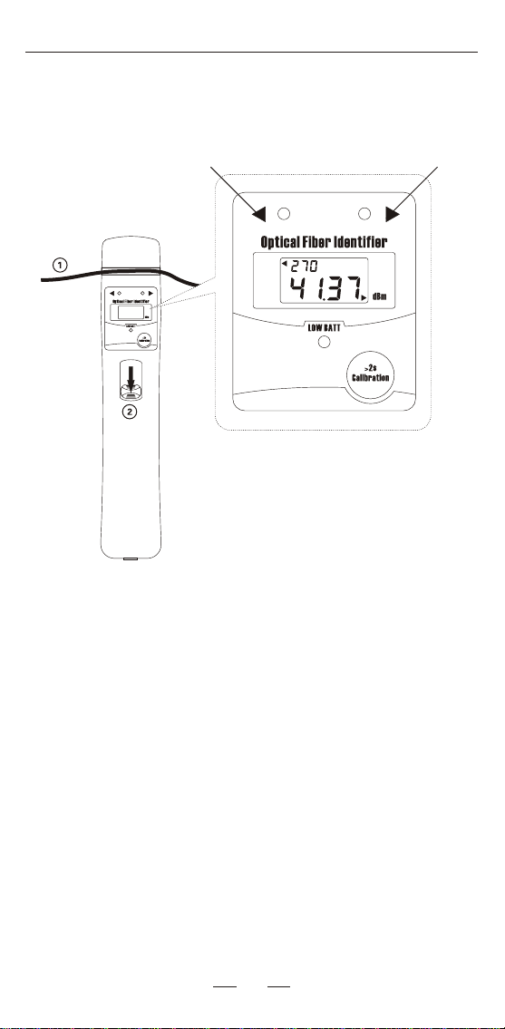
Signal Direction
8
Right to left Left to right
It is themain function to test the direction of the signal
in the fiber. When signalis transporting inthe fiber,the
corresponding indicative led will be on.
Hz
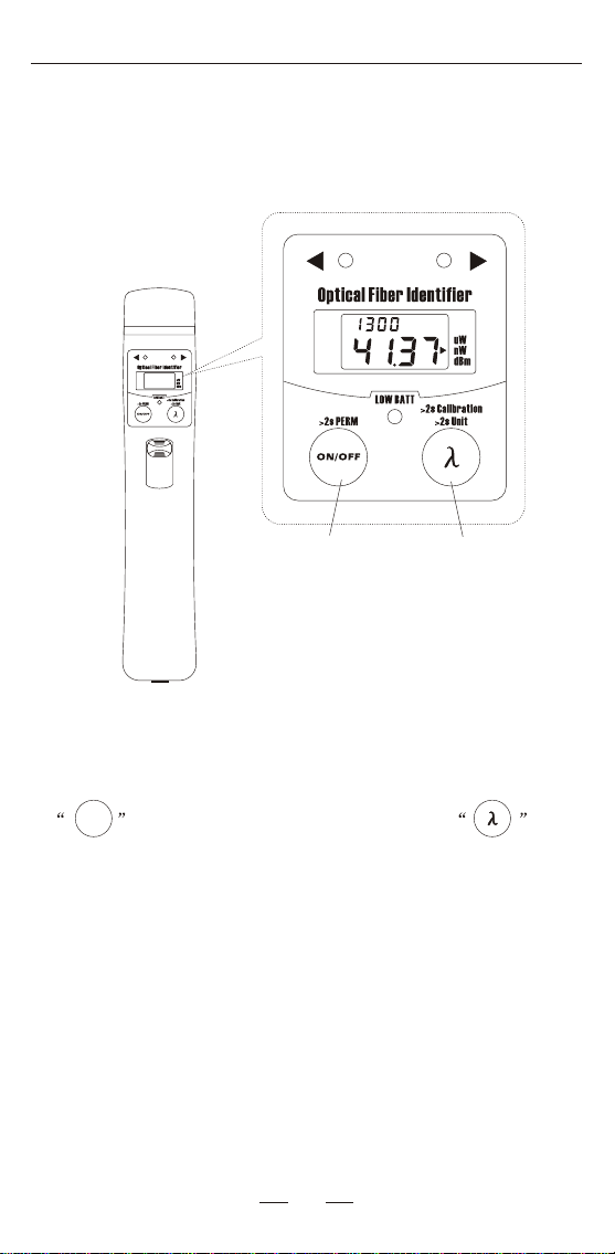
Optical Power Meter
9
ON/OFFON/OFF
Power key Laser source wavelength
switch key
When the opticalfiber identifier hasOPM mode, press
key to turnon the device,short press key
to select thelaser source wavelength.
Open the capin the bottomof the deviceand connect the
fiber correctly, the device will calculate the power value
automatically. The screen will show the corresponding
wavelength and powervalue.
nm
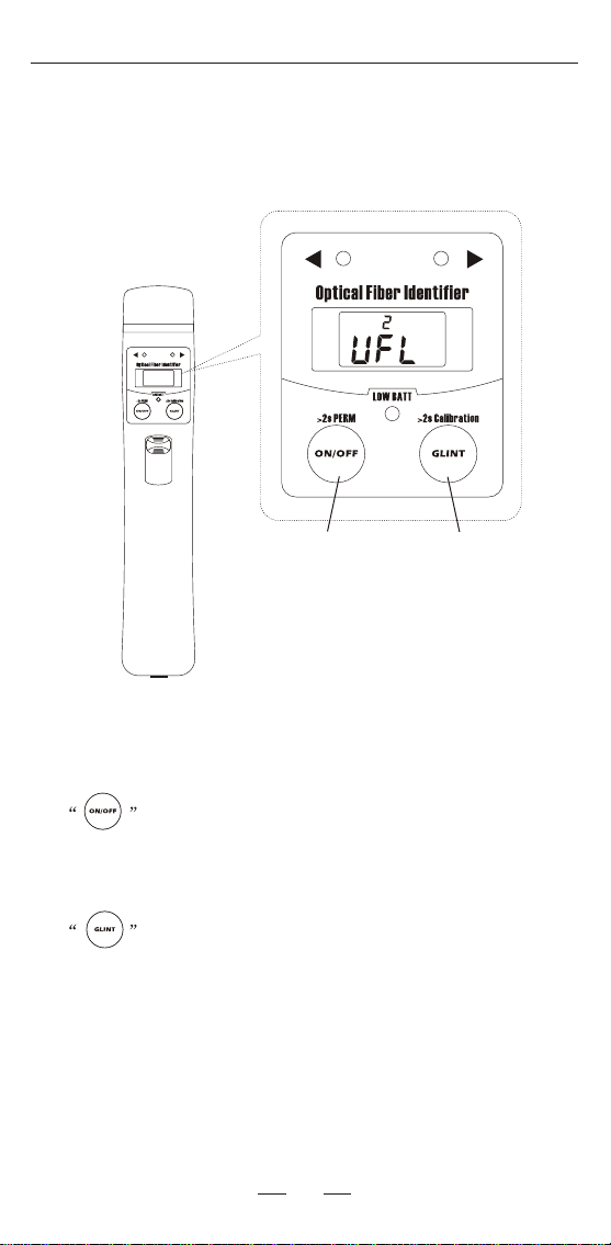
Visual Fault Locator
10
When the opticalfiber identifier has VFL mode,press
key to turnon the device,press again to shut
down.
Open the capin the bottomof the device, and press the
key to openor close the flash laser.
Power key Glint key
ON/OFF
GLINT
>2s SAVE
>2s SAVE
Hz
VFL
GLINT
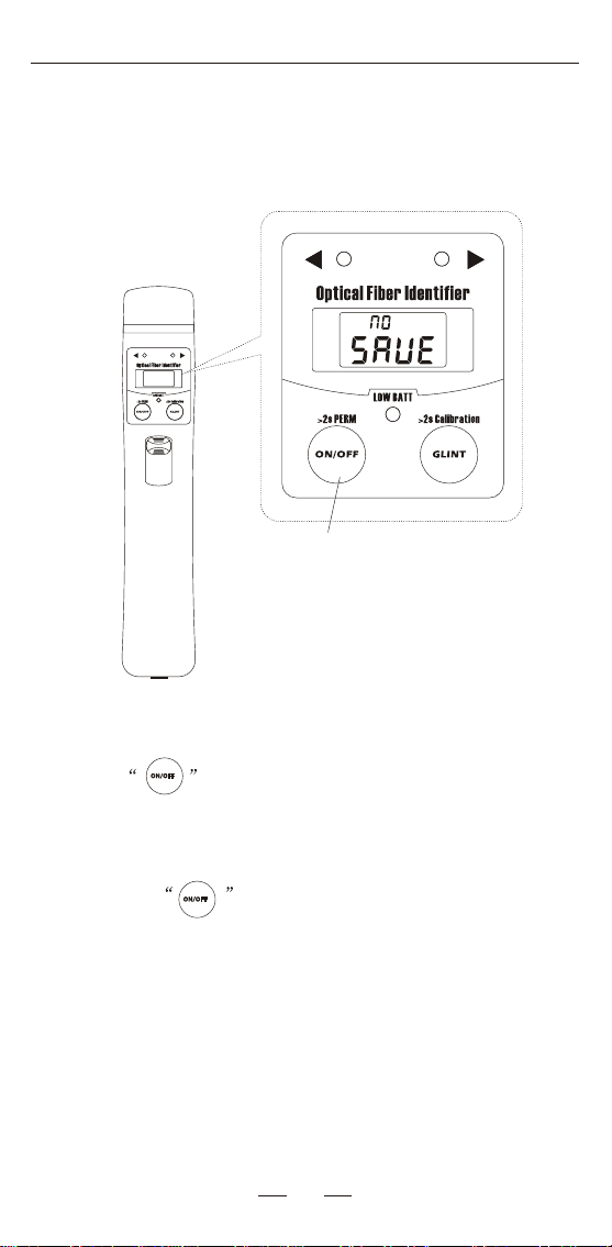
Power saving
Power key
11
Press to turn on the optical power meter or visual
fault locator with auto power of f (
)
After 10 minutes if no key
pressed, it will auto power of f.
Press the key for 2 seconds when turning on the
device, the auto power o will be cancelled and the screen
will show "NO SAVE".
ON/OFF
ON/OFF
Optical Fiber Identifier
>2s SAVE
>2s SAVE
12
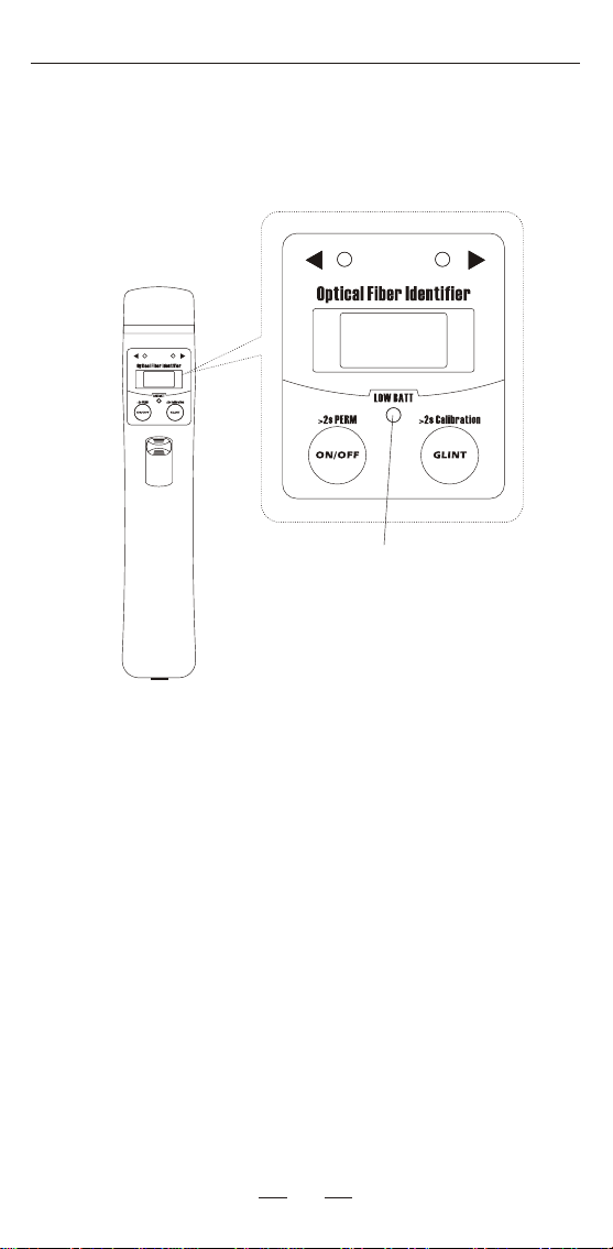
Low power detecting
When the powerindicative led turnsto red, itmeans low
battery energy, please replace the batteries, otherwise the
device will autopower off.
Low power indicativeled
>2s SAVE
Optical Fiber Identifier
>2s SAVE

13
Common malfunction
Described
Can’t turn on
After turn on, it shuts
down immediately
Malfunction cause
Display corrupted
codeReset is incorrect
Can't identify
Wrong identication
Wrong location
Solution
Reset
Test again
Check battery capacity
Unavailable ber
No batteryCheck battery setting
Change battery
Change ber
Maintenance and calibration
Routine attention
1.Fiber-optical adapter should keep clean.
2.Please store the device in dry and ventilated place.
3. Please remove batteries if the device is not being used
regularly to prevent battery leakage.
3mm fiber measurement performance decreases 30%, fiber with black coating can not be
measured, fiber with deep color coating performance decreases 10%~50%.
250um/900um/2.5mm/3mm fiber
14
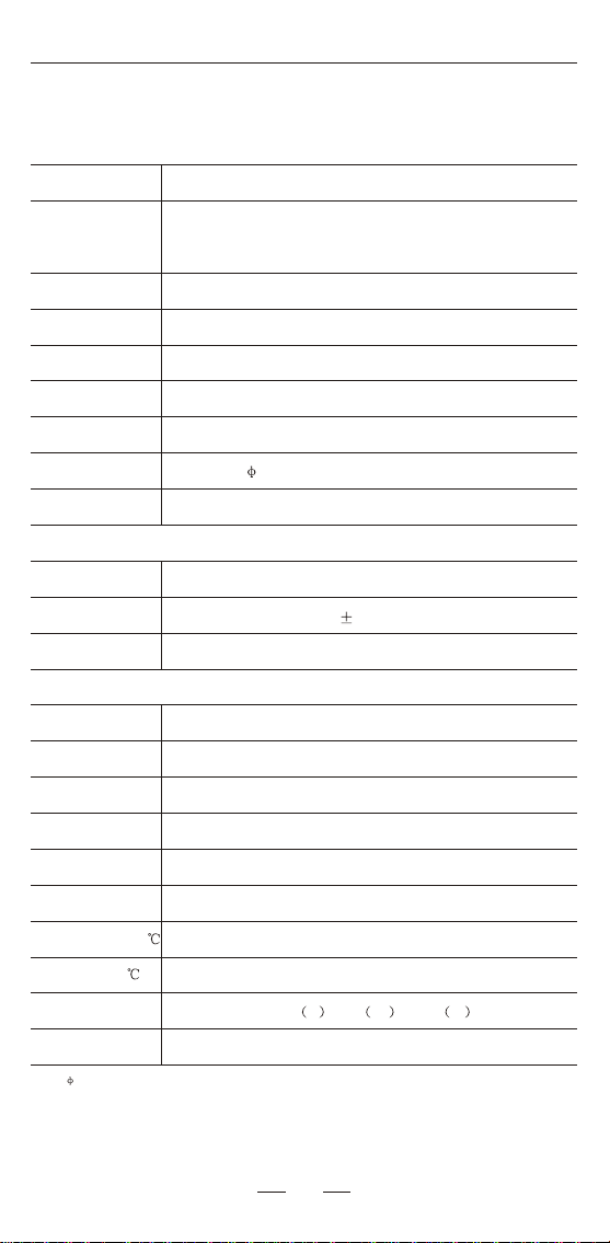
Detailed parameter
<2.5dB typical value
250um fiber@1550nm=-35dBm
900um fiber@1550nm=-35dBm
2.5mm fiber@1550nm=-30dBm
250um fiber@1310nm=-30dBm
900um fiber@1310nm=-30dBm
2.5mm fiber@1310nm=-25dBm
Optical Power Meter
Max. Input
Insertion Loss
Battery Type
Wave Output
Power Output
Frequency Identify
Fiber Type
Sound Warn
Store Temp
Operate Temp
Weight
Size
Detector Type
Optical Adapter
Optical Adapter
Calibration Wave
Accuracy
Yes
Accuracy-CW
Wave respond
Battery life
AA size Alkaline cell or Ni-MH cell
Visual Fault Locator
+5dBm
800nm~1700nm
InGaAs
270Hz/1KHz/2KHz
850nm,1300nm,1310nm,1490nm,1550nm,1625nm
0.02dB
2.5mm UPP
2.5mm UPP
635nm~670nm
1~30mW customized
>6000 times
0---+50
-20---+70
40 L *42 W *230 H
250g

Table of contents
Popular Test Equipment manuals by other brands


Hydrajaws
Hydrajaws M35+ user manual

Tektronix
Tektronix TriMode P7504 Quick start user manual

Tsuruga
Tsuruga 8505 instruction manual

Amptec Research
Amptec Research 620VN Operation & maintenance manual

M&A INSTRUMENTS
M&A INSTRUMENTS YHT-100 Operation instructions

IKONIX
IKONIX 3145 Operation and service manual