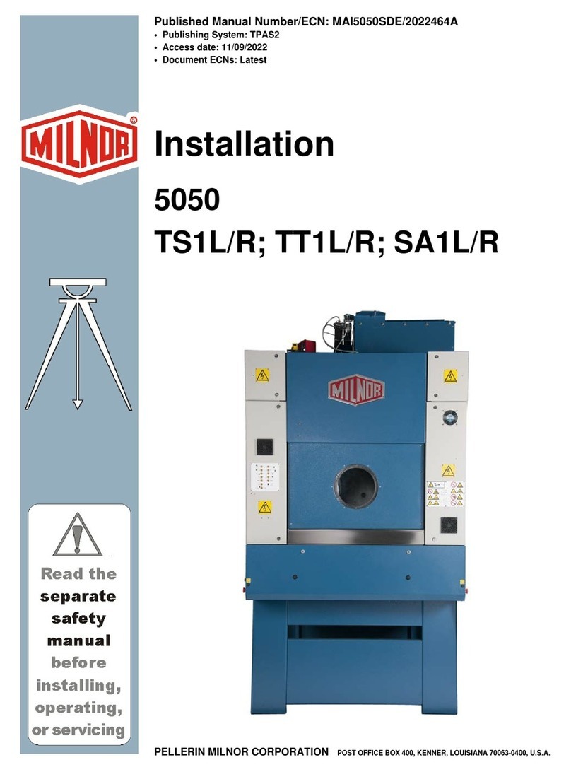
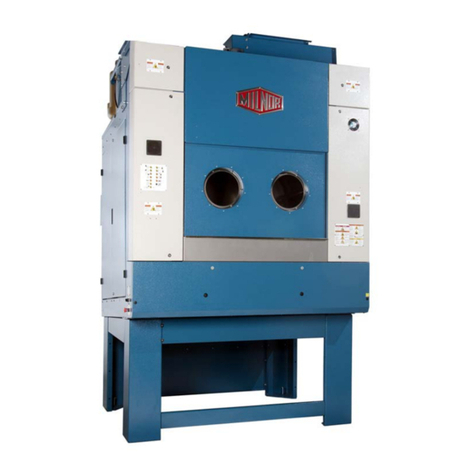
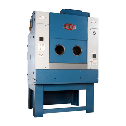
Milnor 5050 User manual

Published Manual Number/ECN: MAP5050ACE/2022246A
• Publishing System: TPAS2
• Access date: 06/10/2022
• Document ECNs: Latest
Service & Mechanical Parts
5050
Shaker, Gas and Steam
Dryers
PELLERIN MILNOR CORPORATION POST OFFICE BOX 400, KENNER, LOUISIANA 70063-0400, U.S.A.


Table of Contents
MAP5050ACE/22246A
Page Description Document
1 Limited Standard Warranty BMP720097/2019036
2 How to Get the Necessary Repair Components BIUUUD19/20081231
3 Trademarks BNUUUU02/2021104A
5 1. Safety
6 Safety—Dryers, Conditioners, and Shakers BIUUUS27PD/20051111
12 Fire Safety System Operation and Maintenance BNDGUH01/2021392
18 Safety Placard Use and Placement 5040, 5050, 6450, 6458,
7272, 7676, 8282 Dryers BMP040034/2021211A
20 Safety Placard Use and Placement - ISO 5040, 5050, 6450,
6458, 6464, 7272, 7676, 8282 Dryers BMP040035/2021211A
23 2. Service and Maintenance
24 Set the Heating System—Air Heat Dryer BNDGUM01/2022223A
36 Torque Requirements for Fasteners BIUUUM04/20180109
45 3. Covers and Shipping Brackets
46 Lifting Brackets BMP040074/2020414A
48 Dryer to Dryer Mounting Parts BMP040075/2020414A
50 Pedestal Base 50040 & 50050 Dryers BMP100006/2012114B
54 Covers - 5040TG2L/R TS2L/R, 5050TG1L/R, TS1L/R BMP100004/2012114B
56 Unload Bridge Installation BMP070009/2020432A
59 4. Drive Assemblies
60 Drive Chart - 5040TG2L/R, TS2L/R; 5050TG1L/R, TS1L/R BMP100007/2012144B
62 Cylinder Installation - 5040TG2L/R, TS2L/R; 5050TG2L/R,
TS2L/R BMP100009/2012114B
64 Guide Roller Assembly BMP100011/2017323A
66 T-Seal Assembly - 5040TG2L/R, TS2L/R; 5050TG1L/R,
TS1L/R BMP100010/2012114B
68 How to Replace the T-Seal MSSM0108AE/198739BV
70 Drive & Support Roller Installation - 5040TG2L/R, TS2L/R;
5050TG1L/R, TS1L/R BMP100008/2012114B
75 5. Door Assemblies
76 Load Door Installation - 5040TG2L/R TS2L/R; 5050TG1L/R,
TS1L/R BMP100018/2012114B
79 Load Door - 5040TG2L/R, TS2L/R; 5050TG1L/R, TS1L/R BMP100019/2012114B
80 Unload Door - 5040TG2L/R, TS2L/R; 5050TG1L/R, TS1L/R BMP100005/2012114B
82 Unload Shroud - 5040TG2L/R, TS2L/R; 5050TG1L/R,
TS1L/R BMP100016/2012114B
83 6. Air Flow Assemblies

Table of Contents, continued
MAP5050ACE/22246A
Page Description Document
84 Blower Installation & Exhaust Duct to Rear - 5040TG2L/R,
TS2L/R; 5050TG1L/R, TS1L/R BMP100012/2012114B
88 Main Air Blower Wheel Replacement BIPD6M06/20100326
91 Blower Bearing 5050, 6450, 6458, 6464, 7272, 7676, 8282
Dryers BMP010033/2020503A
93 Blower Main Damper Air Cylinders BMP070028/2016445A
96 Temperature Sensors - 5040TG2L/R, TS2L/R; 5050TG1L/R,
TS1L/R BMP100020/2012085B
99 7. Gas Assemblies
100 Natural Gas Schematic CSA - 5040TG2L/R; 5050, 6458,
6464, 7272 TG1L/R BMP080027/2012114B
102 Natural Gas Schematic, Europe - 5040TG2L/R; 5050TG1L/R BMP080026/2012114B
104 Gas Piping, CSA and Europe - 5040TG2L/R; 5050TG1L/R BMP080025/2012114B
107 Firebox, Burner & Combustion Air - 5040TG2R/L;
5050TG1R/L BMP100013/2012114B
111 8. Steam Assemblies
112 Steam Coil & Installation - 5040TS2L, 5040TS2R BMP100014/2010095B
114 Steam Coil Damper Air Cylinder, 2-Way - 5040TS2L/R;
5050TS1L/R BMP100015/2012114B
117 9. Water Assemblies
118 Sprinkler Assembly - All Dryers BMP100017/2010096B
121 10. Pneumatic Assemblies
122 Internal Lint Screens BMP130033/2019295A
135 Pneumatic Schematic 5050,6458, 6464, 7272, 8282 Dryers BMP000064/2019295A

BMP720097/19036
PELLERIN MILNOR CORPORATION
LIMITED STANDARD WARRANTY
We warrant to the original purchaser that MILNOR machines including electronic hardware/software
(hereafter referred to as “equipment”), will be free from defects in material and workmanship for a
period of one year from the date of shipment (unless the time period is specifically extended for
certain parts pursuant to a specific MILNOR published extended warranty) from our factory with no
operating hour limitation. This warranty is contingent upon the equipment being installed, operated
and serviced as specified in the operating manual supplied with the equipment, and operated under
normal conditions by competent operators.
Providing we receive written notification of a warranted defect within 30 days of its discovery, we
will—at our option—repair or replace the defective part or parts, EX Factory (labor and freight
specifically NOT included). We retain the right to require inspection of the parts claimed defective in
our factory prior to repairing or replacing same. We will not be responsible, or in any way liable, for
unauthorized repairs or service to our equipment, and this warranty shall be void if the equipment is
tampered with, modified, or abused, used for purposes not intended in the design and construction
of the machine, or is repaired or altered in any way without MILNOR's written consent.
Parts damaged by exposure to weather, to aggressive water, or to chemical attack are not covered
by this warranty. For parts which require routine replacement due to normal wear—such as gaskets,
contact points, brake and clutch linings, belts, hoses, and similar parts—the warranty time period is
90 days.
We reserve the right to make changes in the design and/or construction of our equipment (including
purchased components) without obligation to change any equipment previously supplied.
ANY SALE OR FURNISHING OF ANY EQUIPMENT BY MILNOR IS MADE ONLY UPON THE EXPRESS
UNDERSTANDING THAT MILNOR MAKES NO EXPRESSED OR IMPLIED WARRANTIES OF
MERCHANTABILITY OR FITNESS FOR ANY PARTICULAR USE OR PURPOSE OR ANY OTHER
WARRANTY IMPLIED BY LAW INCLUDING BUT NOT LIMITED TO REDHIBITION. MILNOR WILL NOT
BE RESPONSIBLE FOR ANY COSTS OR DAMAGES ACTUALLY INCURRED OR REQUIRED AS A RESULT
OF: THE FAILURE OF ANY OTHER PERSON OR ENTITY TO PERFORM ITS RESPONSIBILITIES, FIRE
OR OTHER HAZARD, ACCIDENT, IMPROPER STORAGE, MIS-USE, NEGLECT, POWER OR
ENVIRONMENTAL CONTROL MALFUNCTIONS, DAMAGE FROM LIQUIDS, OR ANY OTHER CAUSE
BEYOND THE NORMAL RANGE OF USE. REGARDLESS OF HOW CAUSED, IN NO EVENT SHALL
MILNOR BE LIABLE FOR SPECIAL, INDIRECT, PUNITIVE, LIQUIDATED, OR CONSEQUENTIAL COSTS
OR DAMAGES, OR ANY COSTS OR DAMAGES WHATSOEVER WHICH EXCEED THE PRICE PAID TO
MILNOR FOR THE EQUIPMENT IT SELLS OR FURNISHES.
THE PROVISIONS ON THIS PAGE REPRESENT THE ONLY WARRANTY FROM MILNOR AND NO OTHER
WARRANTY OR CONDITIONS, STATUTORY OR OTHERWISE, SHALL BE IMPLIED.
WE NEITHER ASSUME, NOR AUTHORIZE ANY EMPLOYEE OR OTHER PERSON TO ASSUME FOR US,
ANY OTHER RESPONSIBILITY AND/OR LIABILITY IN CONNECTION WITH THE SALE OR FURNISHING
OF OUR EQUIPMENT TO ANY BUYER.
1

How to Get the Necessary Repair Components
PELLERIN MILNOR CORPORATION
BIUUUD19 (Published) Book specs- Dates: 20081231 / 20081231 / 20081231 Lang: ENG01 Applic: UUU
How to Get the Necessary Repair Components
This document uses Simplified Technical English.
Learn more at http://www.asd-ste100.org.
You can get components to repair your machine from the approved supplier where you got this
machine. Your supplier will usually have the necessary components in stock. You can also get
components from the Milnor®factory.
Tell the supplier the machine model and serial number and this data for each necessary component:
• The component number from this manual
• The component name if known
• The necessary quantity
• The necessary transportation requirements
• If the component is an electrical component, give the schematic number if known.
• If the component is a motor or an electrical control, give the nameplate data from the used
component.
To write to the Milnor factory:
Pellerin Milnor Corporation
Post Office Box 400
Kenner, LA 70063-0400
UNITED STATES
Telephone: 504-467-2787
Fax: 504-469-9777
— End of BIUUUD19 —
2

Pellerin Milnor Corporation
Trademarks
BNUUUU02.R01 0000158093 F.2 E.2 3/3/21 9:47 AM Released
These words are trademarks of Pellerin Milnor®Corporation and other entities:
Table 1. Trademarks
AutoSpot™ GreenFlex™ MilMetrix®PulseFlow®
CBW®GearTrace™ MilTouch™ RAM Command™
Drynet™ GreenTurn™ MilTouch-EX™ RecircONE®
E-P Express®Hydro-cushion™ MILRAIL™ RinSave®
E-P OneTouch®Mentor®Miltrac™ SmoothCoil™
E-P Plus®Mildata®PBW™ Staph Guard®
Gear Guardian®Milnor®
End of document: BNUUUU02
IBNUUUU02 / 2021104A BNUUUU02 0000158094 F.2 3/3/21 9:47 AM Released
3


Safety 1
5

Safety—Dryers, Conditioners, and Shakers
PELLERIN MILNOR CORPORATION
BIUUUS27 (Published) Book specs- Dates: 20051111 / 20051111 / 20060323 Lang: ENG01 Applic: PDU
Safety—Dryers, Conditioners, and Shakers
1. General Safety Requirements—Vital Information for
Management Personnel[Document BIUUUS04]
Incorrect installation, neglected preventive maintenance, abuse, and/or improper repairs, or
changes to the machine can cause unsafe operation and personal injuries, such as multiple
fractures, amputations, or death. The owner or his selected representative (owner/user) is
responsible for understanding and ensuring the proper operation and maintenance of the machine.
The owner/user must familiarize himself with the contents of all machine instruction manuals.
The owner/user should direct any questions about these instructions to a Milnor® dealer or the
Milnor® Service department.
Most regulatory authorities (including OSHA in the USA and CE in Europe) hold the owner/user
ultimately responsible for maintaining a safe working environment. Therefore, the owner/user
must do or ensure the following:
• recognize all foreseeable safety hazards within his facility and take actions to protect his
personnel, equipment, and facility;
• work equipment is suitable, properly adapted, can be used without risks to health or safety,
and is adequately maintained;
• where specific hazards are likely to be involved, access to the equipment is restricted to those
employees given the task of using it;
• only specifically designated workers carry out repairs, modifications, maintenance, or
servicing;
• information, instruction, and training is provided;
• workers and/or their representatives are consulted.
Work equipment must comply with the requirements listed below. The owner/user must verify
that installation and maintenance of equipment is performed in such a way as to support these
requirements:
• control devices must be visible, identifiable, and marked; be located outside dangerous zones;
and not give rise to a hazard due to unintentional operation;
• control systems must be safe and breakdown/damage must not result in danger;
• work equipment is to be stabilized;
• protection against rupture or disintegration of work equipment;
• guarding, to prevent access to danger zones or to stop movements of dangerous parts before
the danger zones are reached. Guards to be robust; not give rise to any additional hazards; not
be easily removed or rendered inoperative; situated at a sufficient distance from the danger
zone; not restrict view of operating cycle; allow fitting, replacing, or maintenance by
restricting access to relevant area and without removal of guard/protection device;
• suitable lighting for working and maintenance areas;
• maintenance to be possible when work equipment is shut down. If not possible, then
protection measures to be carried out outside danger zones;
• work equipment must be appropriate for preventing the risk of fire or overheating; discharges
of gas, dust, liquid, vapor, other substances; explosion of the equipment or substances in it.
6
Safety—Dryers, Conditioners, and Shakers
PELLERIN MILNOR CORPORATION
1.1. Laundr
y
Facilit
y
—Provide a supporting floor that is strong and rigid enough to support–with
a reasonable safety factor and without undue or objectionable deflection–the weight of the fully
loaded machine and the forces transmitted by it during operation. Provide sufficient clearance fo
r
machine movement. Provide any safety guards, fences, restraints, devices, and verbal and/or
posted restrictions necessary to prevent personnel, machines, or other moving machinery from
accessing the machine or its path. Provide adequate ventilation to carry away heat and vapors.
Ensure service connections to installed machines meet local and national safety standards,
especially regarding the electrical disconnect (see the National Electric Code). Prominently post
safety information, including signs showing the source of electrical disconnect.
1.2. Personnel—Inform personnel about hazard avoidance and the importance of care and
common sense. Provide personnel with the safety and operating instructions that apply to them.
Verify that personnel use proper safety and operating procedures. Verify that personnel
understand and abide by the warnings on the machine and precautions in the instruction manuals.
1.3. Safety Devices—Ensure that no one eliminates or disables any safety device on the machine
or in the facility. Do not allow machine to be used with any missing guard, cover, panel or door.
Service any failing or malfunctioning device before operating the machine.
1.4. Hazard Information—Important information on hazards is provided on the machine safety
placards, in the Safety Guide, and throughout the other machine manuals. Placards must be kept
clean so that the information is not obscured. They must be replaced immediately if lost or
damaged. The Safety Guide and other machine manuals must be available at all times to
the appropriate personnel. See the machine service manual for safety placard part numbers.
Contact the Milnor Parts department for replacement placards or manuals.
1.5. Maintenance—Ensure the machine is inspected and serviced in accordance with the norms of
good practice and with the preventive maintenance schedule. Replace belts, pulleys, brake
shoes/disks, clutch plates/tires, rollers, seals, alignment guides, etc. before they are severely
worn. Immediately investigate any evidence of impending failure and make needed repairs (e.g.,
cylinder, shell, or frame cracks; drive components such as motors, gear boxes, bearings, etc.,
whining, grinding, smoking, or becoming abnormally hot; bending or cracking of cylinder, shell,
frame, etc.; leaking seals, hoses, valves, etc.) Do not permit service or maintenance by
unqualified personnel.
2. Safety Alert Messages—Internal Electrical and Mechanical
Hazards[Document BIUUUS11]
The following are instructions about hazards inside the machine and in electrical enclosures.
WARNING 1 : Electrocution and Electrical Burn Hazards—Contact with electric powe
r
can kill or seriously injure you. Electric power is present inside the cabinetry unless the main
machine power disconnect is off.
• Do not unlock or open electric box doors.
• Do not remove guards, covers, or panels.
• Do not reach into the machine housing or frame.
• Keep yourself and others off of machine.
• Know the location of the main machine disconnect and use it in an emergency to remove
all electric power from the machine.
7

Safety—Dryers, Conditioners, and Shakers
PELLERIN MILNOR CORPORATION
WARNING 2 : Entangle and Crush Hazards—Contact with moving components normally
isolated by guards, covers, and panels, can entangle and crush your limbs. These components
move automatically.
• Do not remove guards, covers, or panels.
• Do not reach into the machine housing or frame.
• Keep yourself and others off of machine.
• Know the location of all emergency stop switches, pull cords, and/or kick plates and use
them in an emergency to stop machine motion.
CAUTION 3 : Burn Hazards—Contact with hot goods or machine components can burn you.
• Do not remove guards, covers, or panels.
• Do not reach into the machine housing or frame.
3. Safety Alert Messages—External Mechanical Hazards[Document
BIUUUS12]
The following are instructions about hazards around the front, sides, rear or top of the machine.
4. Safety Alert Messages—Cylinder and Processing Hazards
[Document BIUUUS13]
The following are instructions about hazards related to the cylinder and laundering process.
DANGER 4 : Entangle and Sever Hazards—Contact with goods being processed can
cause the goods to wrap around your body or limbs and dismember you.
• Do not attempt to open the door or reach into the cylinder until the cylinder is stopped.
• Do not touch goods inside or hanging partially outside the turning cylinder.
• Know the location of all emergency stop switches, pull cords, and/or kick plates and use
them in an emergency to stop machine motion.
• Know the location of the main machine disconnect and use it in an emergency to remove
all electric power from the machine.
WARNING 5 : Crush Hazards—Contact with the turning cylinder can crush your limbs. The
cylinder will repel any object you try to stop it with, possibly causing the object to strike or stab
you.
• Do not attempt to open the door or reach into the cylinder until the cylinder is stopped.
• Do not place any object in the turning cylinder.
WARNING 6 : Confined Space Hazards—Confinement in the cylinder can kill or injure
you. Hazards include but are not limited to panic, burns, poisoning, suffocation, heat prostration,
biological contamination, electrocution, and crushing.
• Do not attempt unauthorized servicing, repairs, or modification.
WARNING 7 : Explosion and Fire Hazards—Petroleum and latex materials are
flammable. They can produce explosive fumes when heated.
• Do not use flammable solvents in processing.
• Do not load machine with goods containing dry cleaning materials.
• Do not use the machine in the presence of solvent fumes.
8

Safety—Dryers, Conditioners, and Shakers
PELLERIN MILNOR CORPORATION
WARNING 8 : Poison and Corrosion Hazards—Synthetic solvents such as
perchloroethylene are toxic. They can produce poisonous phosgene gas (mustard gas) and/or
corrosive hydrochloric acid when heated.
• Do not load machine with goods containing dry cleaning materials.
• Do not use the machine in the presence of solvent fumes.
WARNING 9 : Fire Hazards—Overheated goods can catch fire spontaneously in the machine
or after discharge.
• Verify the overheat control system and plant fire extinguishers are functioning before
operating the machine. Be sure to turn water supply on after testing.
• In the event of a fire, thoroughly wet all goods.
• Test or inspect the system after every automatic actuation, or monthly.
CAUTION 10 : Burn Hazards—Contact with hot goods or machine components can burn
you.
• Do not remove guards, covers, or panels.
• Do not reach into the machine housing or frame.
• Use care when handling recently-processed goods.
5. Safety Alert Messages—Unsafe Conditions[Document BIUUUS14]
5.1. Damage and Malfunction Hazards
5.1.1. Hazards Resulting from Inoperative Safety Devices
WARNING 11 : Multiple Hazards—Operating the machine with an inoperative safety device
can kill or injure personnel, damage or destroy the machine, damage property, and/or void the
warranty.
• Do not tamper with or disable any safety device or operate the machine with a
malfunctioning safety device. Request authorized service.
WARNING 12 : Electrocution and Electrical Burn Hazards—Electric box doors—
Operating the machine with any electric box door unlocked can expose high voltage conductors
inside the box.
• Do not unlock or open electric box doors.
WARNING 13 : Entangle and Crush Hazards—Guards, covers, and panels—Operating
the machine with any guard, cover, or panel removed exposes moving components.
• Do not remove guards, covers, or panels.
WARNING 14 : Fire Hazards—Sprinkler and overheat control—Failure to supply water to
the sprinkler or to open the manual valve, or failure of the overheat control, eliminates the
machine's internal fire protection. Normally the machine stops and water is sprayed into the
cylinder if outlet temperature reaches 240 degrees Fahrenheit (116 degrees Celsius).
• Verify the overheat control system and plant fire extinguishers are functioning before
operating the machine. Be sure to turn water supply on after testing.
• Keep the manual shut-off test valve open except when testing.
• Test or inspect the system after every automatic actuation, or monthly.
9

Safety—Dryers, Conditioners, and Shakers
PELLERIN MILNOR CORPORATION
WARNING 15 : Explosion and Fire Hazards—Gas train—Operating the machine with
damaged or malfunctioning gas valves, safeties, controls, or piping can permit gas to escape into
the fire box, cylinder, or laundry room. The enclosure will explode if gas comes in contact with
any spark or flame.
• Do not operate the machine with any evidence of damage or malfunction.
• Stop the machine immediately and alert authorities if you smell gas.
5.1.2. Hazards Resulting from Damaged Mechanical Devices
WARNING 16 : Multiple Hazards—Operating a damaged machine can kill or injure
personnel, further damage or destroy the machine, damage property, and/or void the warranty.
• Do not operate a damaged or malfunctioning machine. Request authorized service.
5.2. Careless Use Hazards
5.2.1. Careless Operation Hazards—Vital Information for Operator Personnel
(
see also
operator hazards throughout manual)
WARNING 17 : Multiple Hazards—Careless operator actions can kill or injure personnel,
damage or destroy the machine, damage property, and/or void the warranty.
• Do not tamper with or disable any safety device or operate the machine with a
malfunctioning safety device. Request authorized service.
• Do not operate a damaged or malfunctioning machine. Request authorized service.
• Do not attempt unauthorized servicing, repairs, or modification.
• Do not use the machine in any manner contrary to the factory instructions.
• Use the machine only for its customary and intended purpose.
• Understand the consequences of operating manually.
CAUTION 18 : Goods Damage and Wasted Resources—Entering incorrect cake data
causes improper processing, routing, and accounting of batches.
• Understand the consequences of entering cake data.
5.2.2. Careless Servicing Hazards—Vital Information for Service Personnel (see also
service hazards throughout manuals)
WARNING 19 : Electrocution and Electrical Burn Hazards—Contact with electric
power can kill or seriously injure you. Electric power is present inside the cabinetry unless the
main machine power disconnect is off.
• Do not service the machine unless qualified and authorized. You must clearly understand
the hazards and how to avoid them.
• Abide by the current OSHA lockout/tagout standard when lockout/tagout is called for in
the service instructions. Outside the USA, abide by the OSHA standard in the absence of
any other overriding standard.
WARNING 20 : Entangle and Crush Hazards—Contact with moving components
normally isolated by guards, covers, and panels, can entangle and crush your limbs. These
components move automatically.
• Do not service the machine unless qualified and authorized. You must clearly understand
the hazards and how to avoid them.
10

Safety—Dryers, Conditioners, and Shakers
PELLERIN MILNOR CORPORATION
• Abide by the current OSHA lockout/tagout standard when lockout/tagout is called for in
the service instructions. Outside the USA, abide by the OSHA standard in the absence of
any other overriding standard.
WARNING 21 : Confined Space Hazards—Confinement in the cylinder can kill or injure
you. Hazards include but are not limited to panic, burns, poisoning, suffocation, heat prostration,
biological contamination, electrocution, and crushing.
• Do not enter the cylinder until it has been thoroughly purged, flushed, drained, cooled,
and immobilized.
— End of BIUUUS27 —
11

Pellerin Milnor Corporation
Fire Safety System Operation and Maintenance
BNDGUH01.C01 0000382704 B.2 9/24/21 11:44 AM Released
NOTICE: If the fire safety system is in operation (if there is a flow of water from the
rear of the dryer)—go to Section 5 : If Water Flow Occurs, page 5.
fire safety system the water nozzles and related equipment that put water in the dryer to stop a
fire in the basket.
Water flow will start automatically if the temperature becomes too high, as told in Section 1 : Fire
Safety Functions and Components, page 1. You can also start it manually. Pull the operation han-
dle or use the control panel as told in Section 4 : How to Do a Test of the Fire Safety System,
page 4. The system will start a flow of water. The water will go into the basket through the perfo-
rations. Do a test of this system at the intervals given in the routine maintenance schedule.
1. Fire Safety Functions and Components
BNDGUH01.C02 0000384000 B.2 9/24/21 11:44 AM Released
This section gives the fire safety functions and components for 6464_ and 7272_ models. Compo-
nents and their locations can be different on other dryer models but the functions are the same.
Table 1. Fire Safety Functions for 6464_ and 7272_ Dryer Models
Sensor type Temperature switch (closes at specified
temperature)
Thermocouple (gives continuous temperature da-
ta to the controller)
Sensor name ST225-1 & 2 ST550A & B STBB T3
Location Basket/outlet
duct (Figure
1, page 2,
Figure 3,
page 2,Fig-
ure 4, page 2)
Inlet duct Fig-
ure 1, page 2,
Figure 2, page
2
At burner
(Figure 1,
page 2,Fig-
ure 5, page
2)
Outlet duct (Figure 3, page 2)
Safety limit (the
temperature or
condition that
causes the given
result)
225° F (107°
C)
550° F (288°
C)
175° F (79°
C)
–Three safety limits in software–
5° F increase for
15 seconds or
15° F increase
for 5 seconds
during min fire*
Higher than
220° F (104° C)
for 5 seconds**
240°F (116°C)
Occurs when
temperature is
too high
Water flows
and all dryer
actions stop.
Flame goes off. If the flame
will not come on, see the line
below this one.
Each step before the cooldown is
subsequently cancelled while the
condition continues.
Water flows and
all dryer func-
tions stop.
Display when
temperature is
too high
THREE
WIRE DIS-
ABLED error
and operator
alarm.
Initially none. If the flame
will not come on, the
CHECK ERROR LIGHTS
error and operator alarm
occur.
The controller
shows “MINF”
and puts data in
the record of dry
cycle details.
The controller
shows “>220”
and puts data in
the record of dry
cycle details.
OUTLET
TEMP EX-
CEEDED 240
Df - POWER
DOWN error
and operator
alarm.
Necessary
procedure
See Section 5
: If Water
Flow Occurs,
page 5
If the error given in the line
above this one occurs, see
“Error Messages” in the op-
erator guide.
See Section 2 : About the Min
Fire and Outlet Temperature Ex-
ceeded 220° Faults, page 3
See Section 5 :
If Water Flow
Occurs, page 5
* This does not apply to steam dryers.
** This does not apply to steam dryers if they do not use modulation.
IBNDGUH01 / 2021392 BNDGUH01 0000382705 B.2 9/24/21 11:44 AM Released
12

Pellerin Milnor Corporation
Figure 1. Component Locations for 6464_ Models
Left, Front, and Right-side Views (model 6464TG1L shown)
Legend
ST225-1 . . Basket temperature switch (upstream of blower). The switch closes at 225° F (107° C).
ST225-2 . . Outlet temperature switch (downstream). The switch closes at 225°F (107°C).
ST550A . . Inlet temperature switch. This switch closes at 550° F (288° C).
ST550B . . Secondary inlet temperature switch. This switch closes at 550° F (288° C).
STBB . . Burner housing temperature switch. This switch closes at 175° F (79° C).
T2..Inlet temperature thermocouple. The fire safety system does not use this component.
T3..Outlet temperature thermocouple. This component gives temperature data to the controller.
1...Sprinkler valve assembly
2...Reset handle
3...Operation handle
Figure 2. View of ST550A, ST550B and T2 Figure 3. View of ST225-1
Figure 4. View of ST225-2 and T3 Figure 5. View of STBB
Fire Safety System Operation and Maintenance
13

Pellerin Milnor Corporation
2. About the Min Fire and Outlet Temperature Exceeded 220°
Faults BNDGUH01.C03 0000384018 B.2 A.2 9/16/21 11:33 AM Released
The function of these faults is to prevent conditions that can cause a fire. The controller does the
necessary steps. There are no other steps for the operator to do immediately. But the controller
puts data about the fault in the record of dry cycle details. These faults usually cause unsatisfac-
tory operation. To prevent these faults, it can be necessary to change some procedures as told in
the subsequent sections. Heat system adjustments and repairs are not routine maintenance. Speak
to your dealer or Milnor®.
2.1. Min Fire (MINF)
BNDGUH01.C04 0000384217 B.2 9/24/21 11:44 AM Released
This condition applies to dryers that use gas or propane. Minimum fire is when the controller tells
the modulating gas valve to go to the position 000. The correct condition is when the gas valve is
open a small, stable increment. Under this condition, a min fire fault occurs if the controller
senses that the outlet temperature increases. This fault usually shows that the goods became too
hot and could catch fire. (One more symptom is if the goods have a burned smell.) When this
fault occurs, the controller immediately goes to the subsequent cool down step. Some causes of
min fire faults include:
•The goods are held against the basket—The correct condition is that the goods tumble in
the basket. If the basket speed is too high, centrifugal force can hold the goods against the
basket. Then the part of the goods that is against the basket can become too hot.
•The gas valve does not operate correctly—For example, the valve throttle cannot move
down fully because it is damaged. This can prevent the min fire position.
•Min fire is set too high—The min fire position must be adjusted correctly when the gas and
air as told in the procedure to set the heat system. Damage to components can cause this ad-
justment to change.
2.2. Outlet Temperature Exceeded 220° (degrees Fahrenheit)
BNDGUH01.C05 0000384216 B.2 A.2 9/16/21 11:33 AM Released
This fault applies to all dryers except those with steam valves that do not modulate. The value
220° F (104° C) is 5°F (3° C) below the temperature that will close the outlet temperature
switches (Fenwal switches) and start water flow. It cancels each subsequent heat step if the outlet
temperature is higher than 220° F (104° C) for five seconds or more at the start of the step. This
fault can also occur if the goods are held against the cylinder or the gas valve is damaged. The
function of this fault is to make water flow not necessary, if the goods are not on fire. But if the
goods catch fire, the temperature switches will quickly close to start water flow.
3. How to Prevent Water Flow When No Fire Occurs
BNDGUH01.C06 0000384215 B.2 9/24/21 11:44 AM Released
If water flow occurs when there is no fire, two possible causes are:
•A temperature switch is damaged. This is the usual cause. For example, material can hit a
temperature probe and bend it. This can be a piece of goods that goes through a space where
Fire Safety System Operation and Maintenance
14

Pellerin Milnor Corporation
seals are worn. It is necessary to replace a damaged probe. The probe can also give an incor-
rect value if it has plastic contamination. It is necessary to remove the contamination.
•Temperatures are not in the correct range. The conditions described in Section 2.1 : Min
Fire (MINF), page 3 can cause water flow if they are severe enough.
If water flow occurs when there is no fire, correct the cause. Do not remove the fire safety sys-
tem from operation. If a fire occurs, this system is your first and best protection against a fire
that is out of control.
4. How to Do a Test of the Fire Safety System
BNDGUH01.T01 0000384214 B.2 9/24/21 11:44 AM Released
1. Prevent a new load: Set the Load Allowed/ Not Allowed ( / ) switch to Not Allowed (
) to prevent a new load.
2. Let the dryer empty: Let the dryer operate until it releases the load it has.
3. Close the manual water valve: Close the valve to prevent water flow. This valve is on the
sprinkler assembly. The assembly is usually on the side of the dryer discharge shroud.
4. Start a test of sprinkler AUTOMATIC operation:
• If there is a controller on the dryer, see “Manual Mode Menu Functions” in the reference
manual.
• If this dryer is part of a Dryer/Shuttle (Drynet™) system, do the steps listed below at the
Drynet™ controller:
a. Select Admin Logon and enter the administrator password.
b. Select (click) the display for the dryer you will do the test on.
c. Select (click) Manual mode.
d. Go to Sprinkler Functions on the right side of the screen and select (click) Sprinkler
[Off] to release the sprinkler valve. This is a toggle. The display shows Sprinkler [On].
5. Examine the automatic sprinkler valve.
CAUTION: Sluggish valve operation — can interfere with fire suppression.
�Remove any build-up of foreign matter on components.
�Make sure components move freely.
6. Let the water flow for a short while: Open the manual valve on the sprinkler assembly.
Make sure that water flows from the rear of the dryer. Close the valve for the subsequent part
of the test.
7. Set the system again: Pull the sprinkler reset handle down fully. It must latch.
8. Start a test of sprinkler MANUAL operation: Select a dry code and run it manually.
CAUTION: The manual water valve must be closed to prevent water flow during
this test.
Fire Safety System Operation and Maintenance
15

Pellerin Milnor Corporation
9. Opereate the fire safety system manually: When the heat source starts to make heat, pull
down the sprinkler operation handle.
10. Make sure that a shutdown occurs:
• The automatic valve opens (the reset handle releases).
• The THREE WIRE DISABLED message appears.
• The operator alarm sounds.
• All dryer functions stop.
11. Stop the dry code.
12. Set the system again: Pull the sprinkler reset handle down fully. It must latch.
13. Open the manual valve.
WARNING: A closed manual valve — will prevent water flow in an emergency.
�Make sure the manual valve is open and remains open during
operation.
14. Put the dryer in operation again.
This concludes the fire safety system test.
5. If Water Flow Occurs BNDGUH01.T02 0000384213 B.2 9/24/21 11:44 AM Released
A serviceable fire safety system will operate if a fire in the basket occurs. But it can also operate
for other causes. Temperature switches (Fenwal switches) in the outlet duct operate the system at
225° F (107° C). If the Fenwal switches are not serviceable, the dryer software operates the sys-
tem at 240° F (116° C).
1. Examine the dryer condition: If there is a fire, let water flow continue until the fire is
extinguished.
CAUTION: Use extreme care if you must look through the door glass or get near a
part of the machine.
2. Set the system again when it is safe:
a. Turn the Master switch off , then on ( ) again. If the software caused the fire safety
system to operate, this is necessary to remove the "Desires Sprinkler" output signal.
b. Pull the sprinkler reset handle down fully. It must latch.
This step helps to keep water damage to a minimum and allows you to use the manual
controls.
3. Did a fire occur?
•NO: Put the dryer in operation again.
•YES: Continue these steps.
Fire Safety System Operation and Maintenance
16
Table of contents
Other Milnor Industrial Equipment manuals

Milnor
Milnor 72046M5K User manual

Milnor
Milnor TS1L/R User manual

Milnor
Milnor 36026X8R Operating manual

Milnor
Milnor COSHR111 Manual

Milnor
Milnor PulseFlow 76028 G3 Manual

Milnor
Milnor CBW Operating manual

Milnor
Milnor 6450TG1L User manual

Milnor
Milnor MP1550 User manual

Milnor
Milnor MWF125J7 User manual

Milnor
Milnor 7676TG1L/R User manual

Milnor
Milnor DRYVAC03 Manual

Milnor
Milnor DRYVAC02 Manual

Milnor
Milnor 48040F7B User manual

Milnor
Milnor 48040M7K User manual

Milnor
Milnor 6450TG1L/R User manual

Milnor
Milnor MT140S1L User manual

Milnor
Milnor MILRAIL User manual

Milnor
Milnor 48040M7K User manual

Milnor
Milnor 5050 TS1L User manual

Milnor
Milnor MWF100C7 User manual