12 13
WARNING!
To reduce the risk of explosion,
never burn a battery pack even if
it is dama ed, dead or completely
dischar ed.
MAINTENANCE
WARNING!
To reduce the risk of personal
injury, always unplu the char er
and remove the battery pack from
the char er or tool before per-
formin any maintenance. Never
disassemble the tool, battery
pack or char er. Contact a
MILWAUKEE service facility for
ALL repairs.
WARNING!
To reduce the risk of personal
injury and dama e, never
immerse your tool, battery pack
or char er in liquid or allow a liquid
to flow inside them.
Maintainin Tool
Keep your tool, battery pack and charger
in good repair by adopting a regular main-
tenance program. After six months to one
year, depending on use, return the tool,
battery pack and charger to a MILWAUKEE
ser ice facility for:
Lubrication
Brush inspection and replacement
Mechanical inspection and cleaning
(gears, spindles, bearings, housing,
etc.)
Electrical inspection (battery pack,
charger, motor)
Testing to assure proper mechanical
and electrical operation
If the tool does not start or operate at full
power with a fully charged battery pack,
clean the contacts on the battery pack. If
the tool still does not work properly, return
the tool, charger and battery pack to a
MILWAUKEE ser ice facility for repairs.
Maintainin Battery Pack
MILWAUKEE battery packs will operate
for many years and/or hundreds of cycles
when they are maintained and used ac-
cording to these instructions.
A battery pack that is stored for six months
without being used will discharge itself.
Batteries discharge at a rate of about 1%
per day. Charge the battery e ery six
months e en if it is unused to maximize
battery life. Do not tape the trigger in the
ON position and lea e the tool unattended
as this may discharge the battery to a point
where it will no longer be able to recharge.
Use a MILWAUKEE battery pack only until
it no longer performs with the power and
torque needed for your application.
ACCESSORIES
For a complete listing of accessories refer
to your MILWAUKEE Electric Tool catalog
or go on-line to www.milwaukeetool.com.
To obtain a catalog, contact your local dis-
tributor or a ser ice center.
Store your battery pack in a cool, dry place.
Do not store it where the temperature may
exceed 120°F (50°C) such as in a ehicle
or metal building during the summer. High
temperatures will o erheat the battery pack,
reducing battery life. If it is stored for se -
eral months, the battery pack will gradu-
ally lose its charge. One to three cycles of
charging and discharging through normal
use will restore the capacity of the battery
pack. During the life of the battery pack,
the operating time between charges be-
comes shorter. If the operating time be-
comes extremely short after a proper
charge, the usable life of the battery pack
has been reached and it should be replaced.
Cleanin
Clean dust and debris from charger and
tool ents. Keep tool handles clean, dry and
free of oil or grease. Use only mild soap and
a damp cloth to clean the tool, battery pack
and charger since certain cleaning agents
and sol ents are harmful to plastics and
other insulated parts. Some of these in-
clude gasoline, turpentine, lacquer thinner,
paint thinner, chlorinated cleaning sol ents,
ammonia and household detergents con-
taining ammonia. Ne er use flammable or
combustible sol ents around tools.
Rechargeable Battery Recycling Corporation
(RBRC). At the end of your battery pack's
useful life, return the battery pack to a
MILWAUKEE Branch Office/Ser ice Center
or the participating retailer nearest you. For
more information, isit the RBRC web site at
www.rbrc.org.
Disposin of Nickel-Cadmium Battery
Packs
Nickel-Cadmium battery packs are recy-
clable. Under arious state and local laws,
it may be illegal to dispose of this battery
into the municipal waste stream. Dispose
of your battery pack according to federal,
state and local regulations.
Repairs
For repairs, return the tool, battery pack
and charger to the nearest ser ice center
listed on the back co er of this operator's
manual.
Battery Pack Warranty
Battery packs for cordless tools are war-
ranted for one year from the date of pur-
chase.
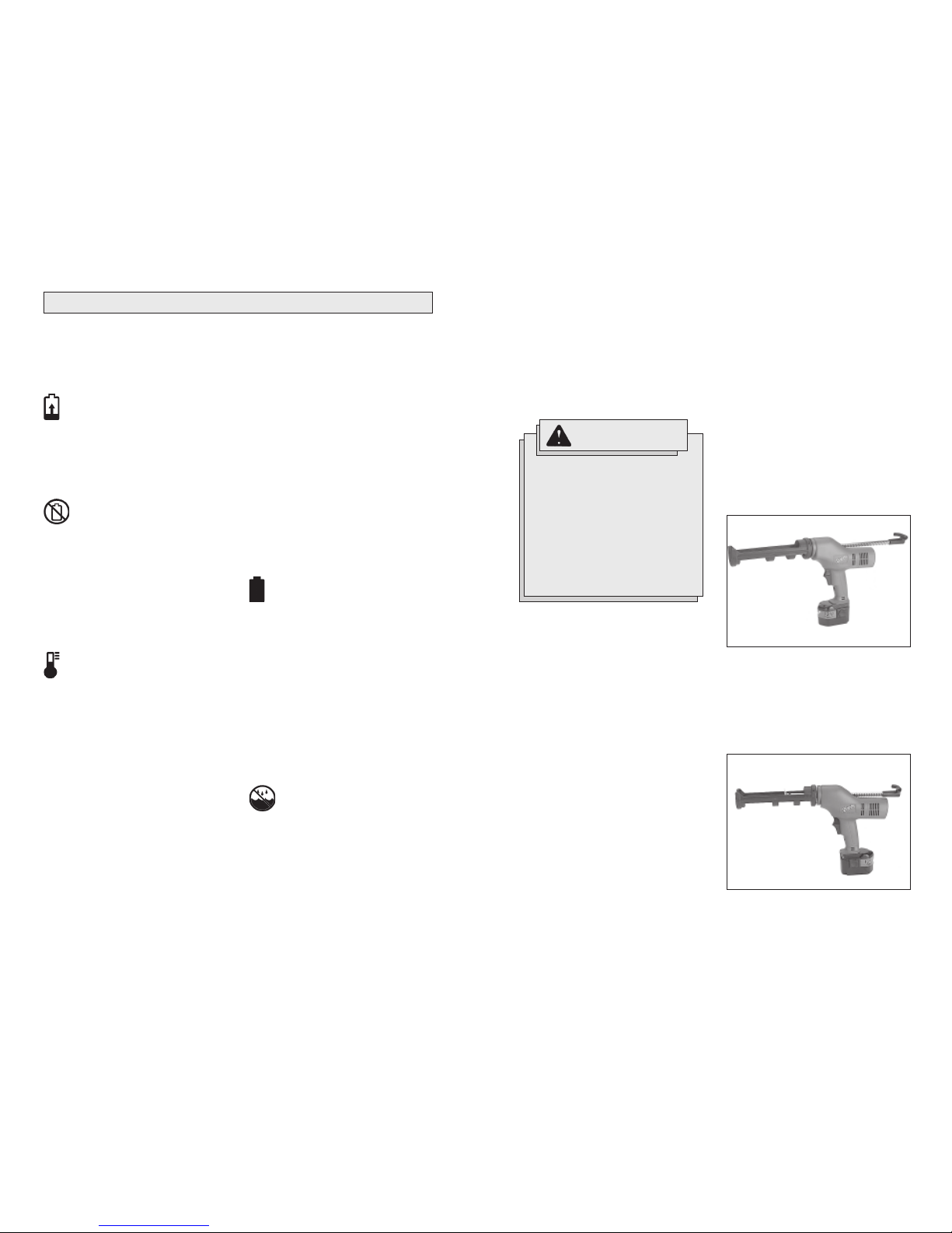
WARNING!
Always remove battery pack be-
fore chan in or removin acces-
sories. Only use accessories spe-
cifically recommended for this
tool. Others may be hazardous.
RBRC Battery Recyclin Seals
The RBRC Battery Recycling Seals (see
"Symbology") on your tool battery packs in-
dicate that MILWAUKEE has arranged for
the recycling of that battery pack with the
FIVE YEAR TOOL
LIMITED WARRANTY
E ery MILWAUKEE tool is tested before
lea ing the factory and is warranted to be
free from defects in material and work-
manship. MILWAUKEE will repair or
replace (at MILWAUKEEs discretion),
without charge, any tool (including battery
chargers) which examination pro es to be
defecti e in material or workmanship from
fi e (5) years after the date of purchase.
Return the tool and a copy of the purchase
receipt or other proof of purchase to a
MILWAUKEE Factory Ser ice/Sales
Support Branch location or MILWAUKEE
Authorized Ser ice Station, freight prepaid
and insured. This warranty does not co er
damage from repairs made or attempted
by other than MILWAUKEE authorized
personnel, abuse, normal wear and tear,
lack of maintenance, or accidents.
Battery Packs, Flashlights, and Radios are
warranted for one (1) year from the date
of purchase.
THE REPAIR AND REPLACEMENT REMEDIES
DESCRIBED HEREIN ARE EXCLUSIVE. IN NO
EVENT SHALL MILWAUKEE BE LIABLE
FOR ANY INCIDENTAL, SPECIAL, OR
CONSEQUENTIAL DAMAGES, INCLUDING
LOSS OF PROFITS.
THIS WARRANTY IS EXCLUSIVE AND IN
LIEU OF ALL OTHER WARRANTIES, OR
CONDITIONS, WRITTEN OR ORAL,
EXPRESSED OR IMPLIED FOR
MERCHANTABLILITY OR FITNESS FOR
PARTICULAR USE OR PURPOSE.
This warranty gi es you specific legal
rights. You may also ha e other rights that
ary from state to state and pro ince to
pro ince. In those states that do not allow
the exclusion of implied warranties or
limitation of incidental or consequential
damages, the abo e limitations or
exclusions may not apply to you. This
warranty applies to the United States,
Canada, and Mexico only.
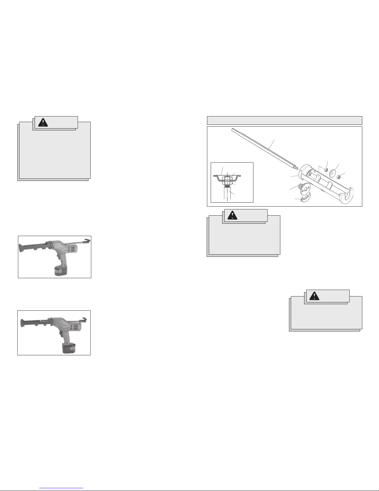
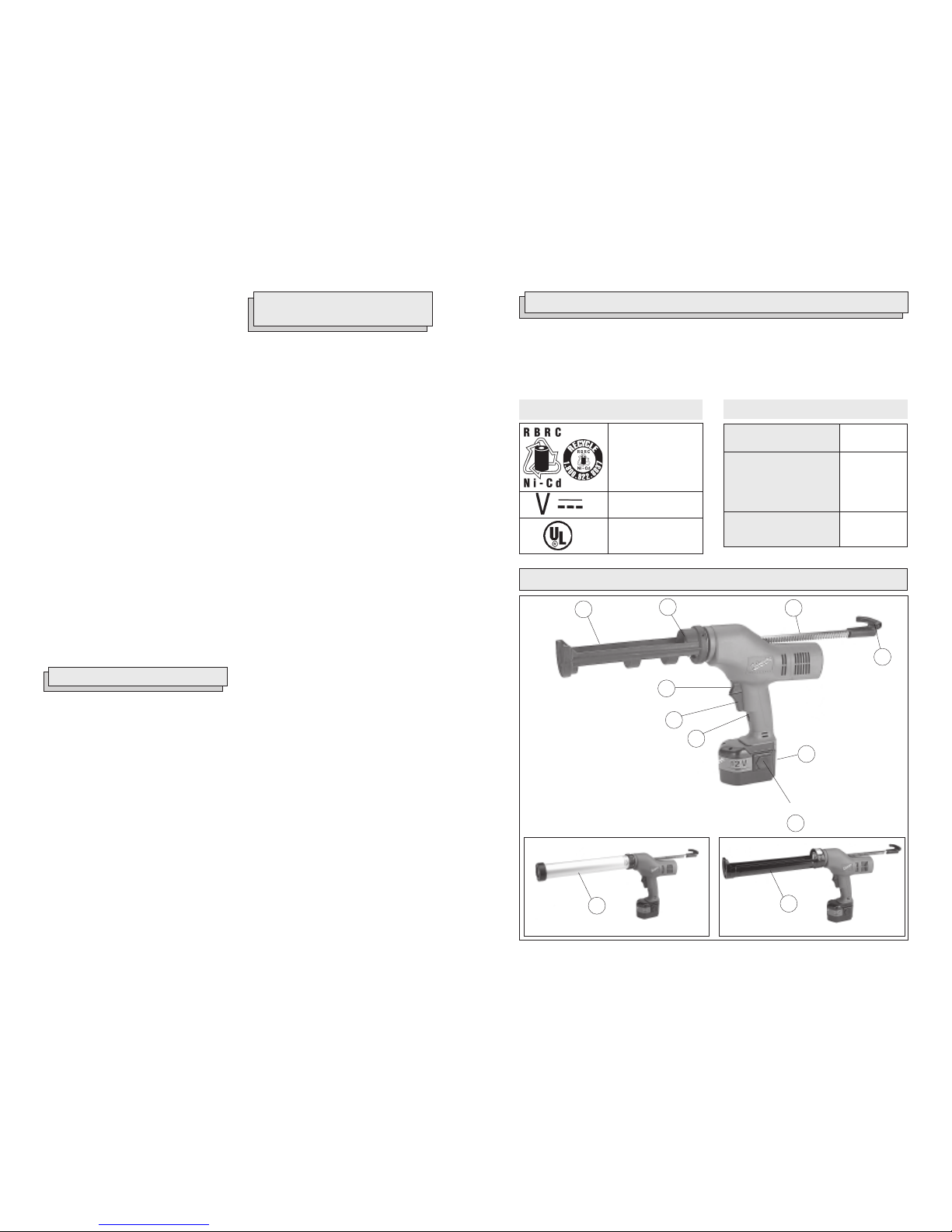
10oz. Carriage Frame Kit
Cat. No. 48-08-1000, must use 49-52-0500 Rack
30oz. Carriage Frame Kit
Cat. No. 48-08-1010, must use 49-52-0525 Rack
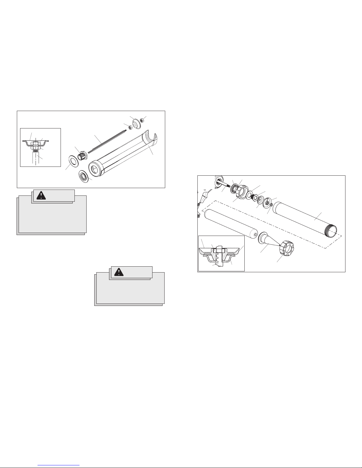
10oz. Sausage Pack Barrel Kit
Cat. No. 48-08-1020, must use 49-52-0500 Rack
20oz. Sausage Pack Barrel Kit
Cat. No. 48-08-1030, must use 49-52-0515 Rack