Mind Media NeXus-10 User manual

Caution: Federal (USA) law restricts this device to sale by or on the order of a physician or licensed practitioner
NeXus-10 MKII
User manual
30-0002-0003
REV 9.0
EN
Last update: 28-03-2022

Page 2of 43
Table of Contents
1Service and support 4
1.1 About this manual 4
1.2 Contact information 4
1.3 Warranty information 4
1.4 Additional accessories or spare parts 5
2Safety information 6
2.1 Explanation of markings 6
2.2 Limitations and contra-indications 8
2.3 Safety measures and warnings 9
2.4 Precautionary measures 10
2.5 Disclosure of residual risk 10
2.6 Information for lays 10
2.7 General advice 11
2.8 Connection to an IT-network 12
3NeXus-10 MKII parts 13
3.1 NeXus-10 MKII main unit 13
3.2 Power pack (NX-BATTERY) 15
3.3 Mains power adapter 16
3.4 Bluetooth USB dongle 16
3.5 USB cable 16
3.6 Device Driver 16
3.7 Device labels 16
3.8 Patient accessories 18
4Description and operational principles 19
4.1 Intended use 19
4.2 Product description 19
4.3 Bipolar input channels 20
4.4 Auxiliary input channels 20
4.5 Digital input channels 20
4.6 Transfer data to PC 20
5Installation 22
5.1 General installation 22
5.2 Driver installation 22
5.3 Bluetooth Pairing Process 22
6Operation 23
6.1 Recharging power pack 23
6.2 (Re)placing power pack 23
6.3 Inserting memory card 24
6.4 Switching on 24
6.5 Switching off 25
6.6 Display of device information 25
6.7 Activating memory card recording 26
6.8 Establishing a Bluetooth connection 27
6.9 Activating Bluetooth recording 28
6.10 Establishing a USB connection 29
6.11 Activating USB recording 29
6.12 Activating Bluetooth/USB recording with memory card logging 30
6.13 Adding markers 31
6.14 Display of device information during recording 31
6.15 Exchange of power pack during recording 32

Page 3of 43
7Troubleshooting 34
8Maintenance 36
9Electromagnetic guidance 37
9.1 Performance 37
9.2 Electromagnetic emission 37
9.3 Electromagnetic immunity 38
10 Technical specifications 40

Page 4of 43
1Service and support
1.1 About this manual
This manual is intended for the user of the NeXus-10 MKII system –also referred to as ‘product’ or
‘NeXus-10 MKII’ throughout this manual. It contains general operating instructions, precautionary
measures, maintenance instructions and information for use of the product. Read this manual
carefully and familiarize yourself with the various controls and accessories before starting to use the
product.
1.2 Contact information
(+31 (0) 475 410123) during office hours (CET). Visit our Support section on www.mindmedia.com,
because this may resolve your problem. Always provide as much information on your problem as
possible, including serial numbers of the products.
Manufacturer
Contact Information
Mind Media B.V.
Louis Eijssenweg 2B
6049 CD Herten
The Netherlands
www.mindmedia.com
+31 (0) 475 410123
Important
In case of need for repair ALWAYS first contact Mind Media Support. The support staff will supply
you with an RMA number in case a return is required. Never ship products back to Mind Media
without this authorization and/or RMA number.
1.3 Warranty information
The product, except its cables and accessories, is warranted against failure of materials and
workmanship for a period of 2 years from the date of delivery. Cables and accessories have a warranty
period of 6 months.
Repairs can only be performed by the manufacturer or personnel authorized by the manufacturer.
Warranty will terminate automatically when the product is opened by any person other than qualified
personnel (authorized by Mind Media).
The warranty does not cover any of the following:
•Failure resulting from misuse, accident, modification, unsuitable physical or operating
environment, or improper maintenance
•Failure caused by a product for which Mind Media is not responsible
•Damage resulting from use of non-approved accessories
•Any non-Mind Media products
The warranty is voided by removal or alteration of identification labels on the product or its parts.
Warranty is also voided in case seals on the enclosure are broken. Mind Media does not warrant
uninterrupted or error-free operation of wired or wireless data transmission.
Any technical or other support provided for a product under warranty, such as assistance with “how-
to” questions and those regarding device set-up and installation, is provided without warranty.

Page 5of 43
1.4 Additional accessories or spare parts
In case you want to order additional accessories such as cables or sensors or spare parts such as

Page 6of 43
2Safety information
This section contains general warnings, explanation of markings, limitations of use, safety measures,
and precautionary measures that are important for the safe use of the product.
2.1 Explanation of markings
This section explains the various markings and symbols used with the product.
Attention: read important safety information
Important information / guidance for use
Consult instructions for use
Device has type BF applied parts
Ingress protection rating
Keep dry
CE-certified (2017/745 Annex II and Annex III), see declaration of conformity
Identification of the manufacturer
Date of manufacture, YYYY-MM-DD
MM reference number
MM serial number
MM medical device name
MM Unique Device Identifier, device identification part
Prescription device
Contains transmitter module
Bluetooth connected
Bluetooth disconnected
USB component

Page 7of 43
USB connected
USB disconnected
Power symbol
Recording to SDHC memory card
Data logging on
SDHC memory card
Power pack (NX-BATTERY) remaining change level
Back-up power charging
Channel indicator (A-H)
Sensor indicator
Unauthorized access
Direct current
Special EU instructions for disposal are applicable to a product on which this symbol
is placed. The Maintenance section of this manual contains information on how to
dispose of this equipment.

Page 8of 43
2.2 Limitations and contra-indications
The following limitations of use are applicable due to relevant regulations and to ensure the device is
able to perform as specified throughout this user manual.
Limitations of use
•Federal (USA) law restricts this device to sale by or on the order of a physician or licensed
practitioner
•The product may only be used under the constant supervision of or on the instructions of
a physician or other authorized medical professional
•The user must have knowledge of current good practice in physiological measurement in
science and clinical application
The product is NOT intended for:
•Critical patient monitoring
•Use in life support systems
The product must not be used, alone or in combination with other devices or software, for the
generation of diagnostic ECG reports.
The product is NOT to be:
•Stored or used near MRI equipment
•Exposed to ionizing radiation
•Used on patients undergoing electro surgery
•Used in oxygen rich environments (concentration > 25 % at 1 atm)
The product is NOT:
•Suitable for use in an environment with inflammable mixture of anesthetics or agents and
air, oxygen or nitrous oxide
•Suitable for use during high frequency cautery of the patient
•Defibrillator proof
•Suitable for sterilization
There are no contra-indications. There are no known side effects from the use of this product.

Page 9of 43
2.3 Safety measures and warnings
The user shall take the following safety measures to ensure that the device can be used safely and
effectively in accordance with its intended use as these are related to risks which are not completely
mitigated as part of the device design. Although it is very unlikely, non-adherence to these measures
may cause severe harm to patient or operator.
Warnings
•Make sure the computer is installed according to local regulations and safety precautions. If
the computer is equipped with a safety earth conductor, use it and connect it to a well-
earthed wall socket.
•Do not place the mains power adapter in the patient environment, i.e. within typically
1.5 meters from the patient.
•The product must be disconnected from patients requiring defibrillation.
•Do not combine the use of the product with any other electronic equipment, except those
specified or referenced in this manual. Doing so may impair the product’s emissions and
immunity regarding EMC.
•The product can only be used with the accessories designated by the manufacturer. The use
of other accessories may impair the product's emissions and immunity regarding EMC.
•The accessories supplied with the product must only be used with the NeXus-10 MKII.
•Do not connect active sensors or electrodes to any of the inputs unless they have been
approved by the manufacturer.
•Transmission quality decreases when there are other radio devices in the neighbourhood.
The wireless transmission may be interfered with by other equipment. Portable RF
communications equipment (including peripherals such as antenna cables and external
antennas) should be used no closer than 30 cm (12 inches) to any part of the NeXus-
10 MKII, including cables connected to it.
•The product should not be used adjacent to or stacked with other equipment. If this is
required, then it should be observed if normal operation of the product in that
configuration is confirmed.
•The product is to be kept dry. If operated outdoors, it must be fitted in a carrying case that
provides an ingress protection of at least IP02.
If liquids or moisture penetrate any part of the product, disconnect the affected part from
all other product parts. If in doubt about safety or performance of the equipment, have it
checked by the manufacturer.
•Do not store or use in environments with equipment capable of emitting diagnostic levels of
ionizing radiation.
•Take care in arranging patient and sensor cables to avoid risk of patient entanglement or
strangulation.
•No modification of this product is allowed. The product should not be tampered with. Do not
abuse the power pack.
•Do not use a power pack other than specified.
•The patient must not touch the connector of the power pack. The operator must not touch
the patient and connector of the power pack simultaneously.
•Do not touch the connector pins of interface plugs or receptacles.
•Do not open the product using tools.

Page 10 of 43
•The product is not to be used when it is clearly damaged or wet, or suspected to be wet
inside.
•The product connectors contain nickel; avoid prolonged skin contact with patients with
nickel allergy.
•Disposable electrodes, which are used for electrophysiological measurements, may be a
biohazard. Handle, and when applicable dispose of these materials in accordance with
accepted medical practice and any applicable local, state and federal laws and regulations.
•Reusable electrodes present a potential risk of cross-infection especially when used on
abraded skin, unless they are restricted to a single patient.
•To prevent contamination: store electrodes separated from the device.
•Do not attempt to service any part of the product while it is in use or connected to a patient.
•There are no user serviceable parts within the product. Repairs can only be performed by
the manufacturer.
2.4 Precautionary measures
The following precautionary measures must be taken by the user to avoid defects or disturbances.
Precautionary measures
•Make sure to prevent electrical contact between conducting parts of accessories and other
equipment.
•Make sure to connect the Patient Ground lead to the patient only.
•Make sure to not connect the NeXus-10 MKII with its accessories simultaneously with other
equipment to the patient.
2.5 Disclosure of residual risk
Any residual risks are disclosed as part of the limitations, warnings and precautionary measures
indicated in the previous sections.
2.6 Information for lays
The product is not intended to be used, configured or operated by lays, outside those actions
necessary and instructed to undergo measurements. The product shall be used only by or under
supervision of a medical professional. The power pack of the device shall be charged sufficiently for
the intended measurement by the operator before starting the recording.
Operators must convey the following information to patients in case they carry the product out of the
professional's office:
•There are no contra-indications.
•Keep the product dry, shield it from direct sunlight and other sources of heat.
•Keep a distance of at least 30 cm between the product and any sources of electromagnetic
fields, such as cell phones, walkie-talkies, CB devices and antennas.
•Be careful when interacting with children and pets to prevent that cables are pulled loose.
•Keep the device clean by staying away from sources of dust, dirt and/or pests.
•Make sure electrodes remain attached where they are, be careful not to get entangled in wires,
not to pull on cables and prevent to fold cables or bend them too sharply.

Page 11 of 43
And, specifically regarding the measurement:
•If there is any indicator or message to look out for on the display, and how to react to it.
•To contact the operator in case of unexpected operation or events.
2.7 General advice
The following general advice should be taken into account by the user to avoid defects or
disturbances.
General advice
•Make sure that the wall socket is well earthed, to reduce 50 or 60 Hz disturbances if the
device is connected to the PC via USB.
•Electrodes and sensors are intended to acquire patient signals. Depending on their mode of
operation they should properly make contact to the patient electrically, thermally and/or
mechanically. Do not let conductive parts of electrodes, sensors and their connectors make
contact to other conductive parts including earth.
Note that the patient ground lead is intended to contact the patient for optimum signal
quality; it is not intended to ‘ground’ the patient to earth.
•The device is not intended to be used simultaneously with other equipment. No problems
are expected with using the device on patients with an implanted device. A pacemaker’s
stimulation pulse or the shock from an implanted cardioverter defibrillator (ICD) may cause
an artefact on the signal that quickly fades. Take care when using the device
simultaneously with other external equipment regarding mutual influence on performance
and summation of leakage currents.
•Reliability of the signal transmission decreases when the distance between the Bluetooth PC
receiver and the device increases or when there are conducting materials in the straight
line between the Bluetooth PC receiver and the device.
•Do not use an operating cellular phone within 50 cm of the device to avoid excessive noise
on the signals.
•Sharp bends or winding the cables in a loop smaller than 5 cm diameter may damage the
cables.
•Do not use sharp objects such as pencil-points or pen-tips to manipulate the buttons on the
control panel, as this can cause damage.
•Dispose of the power pack according to local regulations.
•Do not expose the product to direct sunlight, heat from a source of thermal radiation,
excessive amounts of dust, moisture, vibrations, or mechanical shocks.
•Do not use, store or transport the product outside the specified environmental conditions,
this may damage the product.
Connections to other equipment:
•Connection to the USB port is allowed only from the USB port of a computer via an all-passive
connection; use no separate USB-hub.
•Connection to the Serial sensor input port is allowed only from low voltage equipment that
is powered internally or by the system, and that provides no connection to mains.

Page 12 of 43
2.8 Connection to an IT-network
The following instructions must be observed if NeXus-10 MKII is connected to an IT network.
Instructions
•When connecting the product in an IT-network:
oSimultaneous connection of other equipment to the same USB or Bluetooth network
may result in previously unidentified risks to patients, operators or third parties.
oSuch risks must be identified, analyzed, evaluated and controlled.
oSubsequent changes to the USB or Bluetooth network can introduce new risks that
require additional analysis.
oChanges to the IT-network include: changes to its configuration, connecting additional
items, disconnecting items, updates and upgrades of connected equipment.
•Users of the device must take appropriate measures to protect their PC against cyber
security threats in order to avoid tampering of data or disclosure of patient data which
may be stored, alone or in combination with measurement data on the connected PC.
Such measures include the use of an up-to-date operating system, virus scanners and
protection against access by unauthorized persons.

Page 13 of 43
3NeXus-10 MKII parts
Compare the contents of your purchase with the list below to verify whether all NeXus-10 MKII parts
are present*.
#
Item
Description
1.
Device
The data acquisition device (NeXus-10 MKII device). See Section 3.1.
2.
Power pack
The internal power supply for the device. See Section 3.2. Indicated as
NX-BATTERY on the product label.
3.
Mains power
adapter
The mains power adapter for charging the power pack. See Section 3.3.
4.
Bluetooth USB
dongle
Bluetooth interface to be used on the PC side to provide wireless IT
network with the device. See Section 3.4.
5.
USB cable
USB cable to connect device to the PC. See Section 3.5.
6.
Device Driver
Device driver for USB and application interface. See Section 3.6.
7.
Documentation
This user manual.
* Actual items may differ from this typical scope of delivery. Check package list for actual package contents. In case of unexpected package
contents, contact Mind Media support.
3.1 NeXus-10 MKII main unit
The NeXus-10 MKII main unit contains electronics for measurement, data storage and transmission.
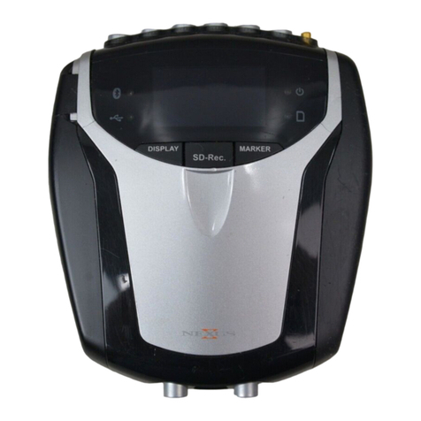
NeXus-10 MKII main unit - Top view
#
Description
1.
Bluetooth indicator light.
2.
Power on/off indicator light.
3.
USB indicator light.
4.
Memory card indicator light.

Page 14 of 43
NeXus-10 MKII main unit - Buttons
#
Description
1.
Display button.
2.
Power/ Memory card recording button.
3.
Marker button.
NeXus-10 MKII main unit –Front view
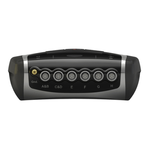
#
Description
1.
Patient Ground input.
2.
A&B - C&D (bipolar) inputs.
3.
E –H (auxiliary) inputs.

Page 15 of 43
NeXus-10 MKII main unit –Rear view
#
Description
1.
Trigger input.
2.
USB port.
3.
Serial sensor input.
3.2 Power pack (NX-BATTERY)
The power pack is a rechargeable battery, for use with the NeXus-10 MKII main unit.
Power pack
#
Description
1.
Connector to NeXus-10 MKII main unit.
2.
Power pack fault indicator light.
3.
Power pack charge indicator light.
4.
Connector for mains power adapter.

Page 16 of 43
3.3 Mains power adapter
Provides power to recharge the power pack. See the label on the adapter, or the Technical
Specifications of the Mains power adapter (Section 10) for technical details.
Note: Only use the power adapter supplied with the device or an equivalent replacement.
Mains power adapter
3.4 Bluetooth USB dongle
For wireless communication with the computer a Bluetooth dongle (i.e. Bluetooth USB adapter) is
used.
3.5 USB cable
For connecting the NeXus-10 MKII to a computer.
USB cable
Note: Only use USB 2.0 compatible cable.
3.6 Device Driver
The latest version of the driver can be downloaded from www.mindmedia.com or by using the USB
support regarding the device driver.
3.7 Device labels
For identification of the NeXus-10 MKII parts, there are three labels: two on the NeXus-10 MKII main
unit (exterior and interior) and one on the power pack.
Exterior label
The exterior label is located on the bottom of the NeXus-10 MKII device and contains generic
information. An example of the exterior label is displayed below. Please note that the actual label
may be different from the picture shown here. Refer to Section 2.1 for an explanation of the symbols
used.

Page 17 of 43
Interior label
The interior label can be found in the power pack compartment of the NeXus-10 MKII, near the
memory card slot. An example of the interior label is displayed below. Please note that the actual
label may be different from the picture shown here. It contains specific information such as the
product code and serial number. Refer to Section 2.1 for an explanation of the symbols used.
#
Description
MD
MM medical device name
REF
MM product code
UDI-DI
MM Unique Device Identifier, device identification part
SN
MM serial number
Power pack label (NX-BATTERY)
The power pack label is placed on the bottom of the power pack. An example of the power pack label
is displayed below. Please note that the actual label may be different from the picture shown here.
Refer to Section 2.1 for an explanation of the symbols used.
#
Description
Type
Product name
Input
Power supply requirements
SN
Serial number
REF
Product code

Page 18 of 43
3.8 Patient accessories
Compatible Mind Media patient accessories can be identified by their type prefix “NB-“, such as the
following:
For BIP inputs: NB-EXG-2BP-S
For AUX inputs: NB-BVP-F, NB-GSR, NB-TMP, NB-RSP
For DIG (serial) input: NB-DMB
The specifications of these patient leads and sensors are in line with the input specifications of the
NeXus-10 MKII (see Section 10) and are designed to operate safely with this device.
More information about approved patient accessories is available on www.mindmedia.com.
Other types of patient accessories may become available. Refer to the respective Mind Media product
information and instructions for use to determine if the accessory is approved for use with NeXus-10
MKII.

Page 19 of 43
4Description and operational principles
4.1 Intended use
The NeXus-10 MKII is designed for medical use, not restricted to a specific medical indication, for the
purpose of acquisition of electrophysiological signals and physiological signals from sensors and other
measuring devices and further transmission of these signals to software running on a general-purpose
computer. The product is intended to be used by medical/research professionals in a laboratory setup
or medical office, or to be set-up in such an environment after which the subject/patient can be sent
out while signal acquisition continues on memory.
The NeXus-10 MKII is not intended for diagnostic purposes because the device does not itself supply
information for detecting, diagnosing, monitoring or treating physiological conditions, states of
health, illnesses or congenital deformities (see definition of active device intended for diagnosis and
monitoring in 2.5 of Annex VIII).
The device is not intended for use in critical and/or life supporting applications. The NeXus-10 MKII is
intended for use on humans. There are no known contra-indications.
The NeXus-10 MKII is intended to be used with approved NeXus-10 MKII accessories only. Specifically,
(active) sensors intended to measure specific physiological signals and to be used with the device shall
be designed in accordance with the specifications of the NeXus-10 MKII. The signal data acquired by
the NeXus-10 MKII requires interpretation by the user.
For stationary measurements the device transfers the data to the PC by means of a wired USB or
wireless (Bluetooth) connection, where the signals can be viewed or stored for further processing.
The device is powered by an internal power supply. For ambulatory measurements the data can be
stored on a SDHC card within the NeXus-10 MKII and retrieved by the operator.
Important
The product does not perform any signal interpretation or signal analysis. This is left to the
physician/licensed practitioner.
The operator (or application software) shall verify the (raw) measurement data to ensure signals
are free of artefacts introduced by defective sensor accessories, incorrect placement of electrodes
or environmental interference.
The product is not intended for use in a life support application.
The product must not be used, alone or in combination with other devices or software, for the
generation of diagnostic ECG reports.
For stationary measurements the device transfers the data to the PC by means of a wired USB or
wireless (Bluetooth) connection, where the signals can be viewed or stored for further processing.
The device is powered by an internal power supply.
For ambulatory measurements the data can be stored on a SDHC card within the NeXus-10 MKII and
retrieved by the operator.
4.2 Product description
The NeXus-10 MKII is a general-purpose signal acquisition system for high-quality physiological
measurements. It is intended for use with application software for data analysis and presentation.
The NeXus-10 MKII main unit (NeXus-10) contains the electronics for amplification, digitization,
storage, and wireless transmission. The NeXus-10 MKII uses an exchangeable power pack as power

Page 20 of 43
supply, which contains a rechargeable lithium-polymer battery. Sensors and electrodes
simultaneously connect to the NeXus-10 MKII.
The power pack is charged (while not connected to the NeXus-10 MKII) through a mains power
adapter. The NeXus-10 MKII is able to interface through USB or a wireless Bluetooth connection to a
computer. The latter requires installation of the Bluetooth dongle on a USB 2.0 port of the computer.
In addition, NeXus-10 MKII is capable of storing measurement data on a SDHC memory card.
The NeXus-10 MKII contains true DC amplifiers with very low input noise, very high input impedance
and very high common mode rejection.
4.3 Bipolar input channels
The input stage for measuring bipolar electrophysiological signals is configured as an instrumentation
amplifier. The difference between a ‘plus’ and ‘minus’ signal is amplified. The patient ground
electrode is required to keep patient potential and amplifier potential at about the same level. Do
NOT connect the patient ground to mains earth, safety earth or a potential equalization terminal.
All electrode cables are shielded with the average of the ‘plus’ and ‘minus’ electrode signal (active
shielding). The active shielding ensures that disturbances such as cable movement artefacts and
mains interference (50/60 Hz) are reduced to a minimum.
After the first amplifier stage (gain = 20) the signals go directly to the ADC. No high pass or low pass
filters are present that can cause significant signal phase shifts or filter overflows for frequencies up
to half of the sampling frequency.
4.4 Auxiliary input channels
Each auxiliary input has a 5-pin connector. Signals on this connector are +5V output, -5V output, GND,
+signal input and -signal input. The +5V/-5V/GND pins can be used to power an active sensor. The +
and - inputs are connected to an instrumentation amplifier with a gain of 1. The output of the
amplifier goes to the ADCs without any filtering for frequencies up to half of the sampling frequency.
4.5 Digital input channels
The digital inputs allow connection of additional accessories, these inputs are isolated from the
bipolar and auxiliary inputs of the device.
Trigger input
The trigger input can be used to record event markers in parallel with the physiological data.
Serial sensor input
The serial sensor input can be used to transfer serial data from a digital sensor.
4.6 Transfer data to PC
Both USB and Bluetooth IT-network connections are supported by the product. The purpose of the
IT-network connection is for device control and/or data transfer. The intended information flow is:
•Control from a PC to the device
•Raw data from the device to the PC
The supported versions of the IT network connections are:
•USB: 2.0 and higher
•Bluetooth: 1.1 and higher
The following section describes the installation of the USB link and Bluetooth IT-network connections.
Table of contents
Other Mind Media Medical Equipment manuals
Popular Medical Equipment manuals by other brands

DFI
DFI MD711-SU user manual

Joerns Healthcare
Joerns Healthcare DermaFloat APM User & service manual

Ofa Bamberg
Ofa Bamberg Dynamics plus manual

Maico
Maico DRD Ex Series Original installation and operating instructions

Breg
Breg 100628-020 Instructions for use

Moller Medical
Moller Medical Vibrasat power Instructions for use