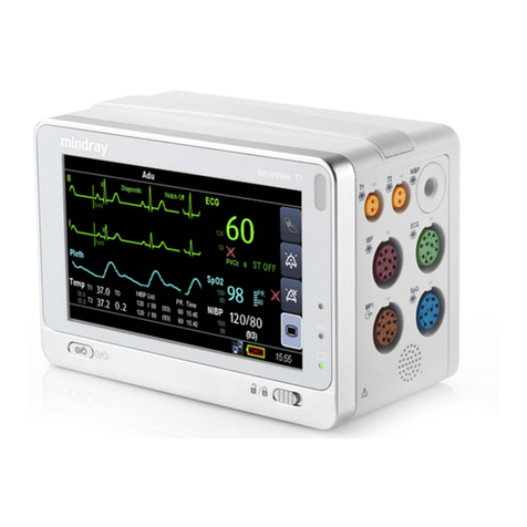
Mindray PM-7000 User manual

PM-7000
Patient Monitor
Service Manual


Service Manual
I
Copyright
Statement
SHENZHEN MINDRAY BIO-MEDICAL ELECTRONICS CO., LTD. (hereinafter called Mindray)
owns all rights to this unpublished work and intends to maintain this work as confidential.
Mindray may also seek to maintain this work as an unpublished copyright. This publication is to
be used solely for the purposes of reference, operation, maintenance, or repair of Mindray
equipment. No part of this can be disseminated for other purposes.
In the event of inadvertent or deliberate publication, Mindray intends to enforce its rights to this
work under copyright laws as a published work. Those having access to this work may not
copy, use, or disclose the information in this work unless expressly authorized by Mindray to
do so.
All information contained in this publication is believed to be correct. Mindray shall not be liable
for errors contained herein nor for incidental or consequential damages in connection with the
furnishing, performance, or use of this material. This publication may refer to information and
protected by copyrights or patents and does not convey any license under the patent rights of
Mindray, nor the rights of others. Mindray does not assume any liability arising out of any
infringements of patents or other rights of third parties.
Content of this manual is subject to changes without prior notice.
PROPERTY OF SHENZHEN MINDRAY BIO-MEDICAL ELECTRONICS CO., LTD.
ALL RIGHTS RESERVED
Responsibility on the manufacturer party
Mindray is responsible for safety, reliability and performance of this equipment only in the
condition that:
•all installation, expansion, change, modification and repair of this equipment are conducted
by Mindray qualified personnel;
•applied electrical appliance is in compliance with relevant National Standards;
•the monitor is operated under strict observance of this manual.
Warning
For continued safe use of this equipment, it is necessary that the listed instructions are
followed. However, instructions listed in this manual in no way supersede established medical
practices concerning patient care.
zDo not rely only on audible alarm system to monitor patient. When monitoring

Service Manual
II
adjusting the volume to very low or completely muting the sound may result in the
disaster to the patient. The most reliable way of monitoring the patient is at the
same time of using monitoring equipment correctly, manual monitoring should be
carried out.
zThis multi-parameter patient monitor is intended for use only by medical
professionals in health care institutions.
zTo avoid electrical shock, you shall not open any cover by yourself. Service must be
carried out by qualified personnel.
zUse of this device may affect ultrasonic imaging system in the presence of the
interfering signal on the screen of ultrasonic imaging system. Keep the distance
between the monitor and the ultrasonic imaging system as far as possible.
zIt is dangerous to expose electrical contact or applicant coupler to normal saline,
other liquid or conductive adhesive. Electrical contact and coupler such as cable
connector, power supply and parameter module socket-inlet and frame must be
kept clean and dry. Once being polluted by liquid, they must be thoroughly dried. If
to further remove the pollution, please contact your biomedical department or
Mindray.
It is important for the hospital or organization that employs this equipment to carry out a
reasonable maintenance schedule. Neglect of this may result in machine breakdown or injury
of human health.

Service Manual
III
Warranty
THIS WARRANTY IS EXCLUSIVE AND IS IN LIEU OF ALL OTHER WARRANTIES,
EXPRESSED OR IMPLIED, INCLUDING WARRANTIES OF MERCHANT ABILITY OR
FITNESS FOR ANY PARTICULAR PURPOSE.
Exemptions
Mindray's obligation or liability under this warranty does not include any transportation or other
charges or liability for direct, indirect or consequential damages or delay resulting from the
improper use or application of the product or the substitution upon it of parts or accessories not
approved by Mindray or repaired by anyone other than a Mindray authorized representative.
This warranty shall not extend to any instrument which has been subjected to misuse,
negligence or accident; any instrument from which Mindray's original serial number tag or
product identification markings have been altered or removed, or any product of any other
manufacturer.
Safety, Reliability and Performance
Mindray is not responsible for the effects on safety, reliability and performance of the
PM-7000 Patient Monitor if:
■ assembly operations, extensions, re-adjusts, modifications or repairs are carried out
by persons other than those authorized by Mindray.
■ the PM-7000 is not used in accordance with the instructions for use, or the electrical
installation of the relevant room does not comply with NFPA 70: National Electric
Code or NFPA 99: Standard for Health Care Facilities (Outside the United States, the
relevant room must comply with all electrical installation regulations mandated by the
local and regional bodies of government).

Service Manual
IV
Return Policy
Return Procedure
In the event that it becomes necessary to return a unit to Mindray, the following procedure
should be followed:
1. Obtain return authorization. Contact the Mindray Service Department and obtain a
Customer Service Authorization (Mindray) number. The Mindray number must appear on
the outside of the shipping container. Return shipments will not be accepted if the Mindray
number is not clearly visible. Please provide the model number, serial number, and a brief
description of the reason for return.
2. Freight policy. The customer is responsible for freight charges when equipment is shipped
to Mindray for service (this includes customs charges).
Company Contact
Manufacture: Shenzhen Mindray Bio-Medical Electronics Co., Ltd.
Address: Mindray Building, Keji 12th Road South, Hi-tech Industrial
Park, Nanshan, Shenzhen 518057, P.R.China
Phone: +86 755 26582479 26582888
Fax: +86 755 26582934 26582500

Service Manual
V
Safety Precautions
1. Meaning of Signal Words
In this manual, the signal words DANGER, WARNING, and CAUTION are used
regarding safety and other important instructions. The signal words and their meanings are
defined as follows. Please understand their meanings clearly before reading this manual.
Signal word Meaning
DANGER Indicates an imminently hazardous situation which, if not
avoided, will result in death or serious injury.
WARNING Indicates a potentially hazardous situation which, if not avoided,
could result in death or serious injury.
CAUTION Indicates a potentially hazardous situation which, if not avoided,
may result in minor or moderate injury.
2. Meaning of Safety Symbols
Symbol Description
Type-BF applied part
"Attention" (Refer to the operation manual.)
Safety Precautions
Please observe the following precautions to ensure the safety of service engineers as well as
operators when using this system.
DANGER: Do not use flammable gases such as anesthetics, or flammable
liquids such as ethanol, near this product, because there is danger
of explosion.
WARNING: Do not connect this system to outlets with the same circuit
breakers and fuses that control current to devices such as
life-support systems. If this system malfunctions and
generates an over current, or when there is an instantaneous

Service Manual
VI
current at power ON, the circuit breakers and fuses of the
building’s supply circuit may be tripped.
CAUTION: 1. Malfunctions due to radio waves
(1) Use of radio-wave-emitting devices in the proximity of this
kind of medical electronic system may interfere with its
operation. Do not bring or use devices which generate radio
waves, such as cellular telephones, transceivers, and radio
controlled toys, in the room where the system is installed.
(2) If a user brings a device which generates radio waves near the
system, they must be instructed to immediately turn OFF the
device. This is necessary to ensure the proper operation of
the system.
2. Do not allow fluids such as water to contact the system or
peripheral devices. Electric shock may result.

Service Manual
VII
Symbols
Equipotential grounding
terminal
CE mark 93/42/EEC a
directive of the European
Economic Community
Be Careful
Protective earth ground
Direct current and alternating
current (DC&AC) Direct current (DC)
Alternating current (AC) Battery indicator
ESD sensitivity
Power ON/OFF
Network connector
High voltage
Indicates that the instrument is IEC-60601-1 Type CF equipment. The unit
displaying this symbol contains an F-Type isolated (floating) patient
applied part providing a high degree of protection against shock, and is
suitable for use during defibrillation.

Service Manual
I
Contents
Chapter 1 About the Product .....................................................................................................1
1.1 Introduction......................................................................................................................1
1.2 Application .......................................................................................................................1
1.2.1 General ......................................................................................................................1
1.3 Environment ....................................................................................................................3
1.3.1 Temperature.............................................................................................................3
1.3.2 Humidity ...................................................................................................................3
1.3.3 Electrical specification ..............................................................................................3
Chapter 2 Principles....................................................................................................................4
2.1 General ............................................................................................................................4
2.1.1 Parameter Measurement............................................................................................5
2.1.2 Main Control Part......................................................................................................5
2.1.3 Man-Machine Interface.............................................................................................5
2.1.4 Power Supply ............................................................................................................5
2.1.5 Other Auxiliary Functions.........................................................................................5
2.2 Hardware Description .......................................................................................................6
2.2.1 Main Board ...............................................................................................................7
2.2.2 ECG/RESP/TEMP Module .......................................................................................9
2.2.3 CO/IBP Module....................................................................................................... 11
2.2.4 SpO2Module...........................................................................................................12
2.2.5 NIBP Module ..........................................................................................................13
2.2.6 Recorder Module.....................................................................................................14
2.2.7 Button Panel............................................................................................................15
2.2.8 Power PCB..............................................................................................................16
2.3 Software Description.......................................................................................................17
2.3.1 General ....................................................................................................................17
2.3.2 System Task.............................................................................................................18
2.3.3 System Function.............................................................................................................19
2.4 System Parameter............................................................................................................20
2.4.1 General ....................................................................................................................20
2.4.2 ECG/RESP ..............................................................................................................20
2.4.3 NIBP........................................................................................................................21
2.4.4 SpO2........................................................................................................................22
2.4.5 TEMP ......................................................................................................................22
2.4.6 IBP ..........................................................................................................................22
2.4.7 CO ...........................................................................................................................23
2.4.8 CO2..........................................................................................................................23
2.4.9 AG...........................................................................................................................23

Service Manual
II
Chapter 3 Product Specifications .................................................................................................25
3.1 Safety Classifications............................................................................................................25
3.2 Environmental Specifications ...............................................................................................26
3.3 Power Source Specifications.................................................................................................27
3.4 Hardware Specifications .......................................................................................................28
3.5 Wireless network...................................................................................................................29
3.6 Data Storage..........................................................................................................................30
3.7 Signal Output Specifications...........................................................................................31
3.8 ECG Specifications .........................................................................................................32
3.9 RESP Specifications..............................................................................................................34
3.10 SpO2Specifications.............................................................................................................35
1.1.1. Mindray SpO2Module ..................................................................................................35
1.1.2. Masimo SpO2Specifications.........................................................................................35
1.1.3. Nellcor SpO2Specifications..........................................................................................36
3.11 IBP Specifications...........................................................................................................37
3.12 TEMP Specifications...........................................................................................................38
3.13 IBP Specifications...............................................................................................................39
3.14 CO Specifications ...............................................................................................................40
3.15 CO2Specifications ..............................................................................................................41
1.1.4. Mindray CO2Specifications .........................................................................................41
1.1.5. Oridion CO2Specifications...........................................................................................42
1.1.6. Welch Allyn CO2Specifications ...................................................................................43
3.16 AG Specifications ...............................................................................................................44
Chapter 4 Disassembling/Assembling & Troubleshooting .............................................................47
4.1 PM-7000 Disassembling/Assembling.............................................................................47
4.1.2 PM-7000 Support Assembly ..........................................................................................48
4.1.3 Front Bezel Assembly ....................................................................................................50
4.1.4 Rear Housing Assembly.................................................................................................51
4.1.5 Microstream CO2Assembly...........................................................................................52
4.2 Troubleshooting ............................................................................................................53
4.2.1 Black Screen, Startup Failure ...................................................................................53
4.2.2 White Screen & Other Abnormal Screen ................................................................54
4.2.3 Encoder Faults............................................................................................................54
4.2.4 No Audio Alarm ...........................................................................................................54
4.2.5 Printing Failure............................................................................................................54
4.2.6 Abnormal Paper Drive................................................................................................54
Chapter 5 Test and Material List .............................................................................................55
5.1 Test Procedure..............................................................................................................55
5.1.1 Connection and Checking .........................................................................................55
5.1.2 Functions of Buttons ..................................................................................................55
5.1.3 ECG/RESP ..................................................................................................................55
5.1.4 Temperature ................................................................................................................56

Service Manual
III
5.1.5 NIBP...............................................................................................................................56
5.1.6 SpO2...............................................................................................................................56
5.1.7 IBP .................................................................................................................................56
5.1.8 CO ..................................................................................................................................57
5.1.9 CO2.................................................................................................................................57
5.1.10 Recorder .......................................................................................................................58
5.1.12 Power Supply ...............................................................................................................58
5.1.13 Clock ............................................................................................................................58
5.1.14 System Test ..................................................................................................................58
5.2 NIBP Calibration.............................................................................................................59
5.3 IBP CALIBRATE..............................................................................................................59
5.4 CO2 CHECK.......................................................................................................................62
5.5 AG CALIBRATE .................................................................................................................64
5.5.1 AG Check.....................................................................................................................64
5.5.2 AG CALIBRATE ..........................................................................................................65
5.6 Bill of Materials for PM-7000 Main Unit .......................................................................66
Chapter 6 Maintenance and Cleaning .............................................................................................67
6.1 Maintenance ..........................................................................................................................67
6.1.1Checking Before Using...................................................................................................67
6.1.2 Regular Checking...........................................................................................................67
6.2 Cleaning ..........................................................................................................................67
6.3 Cleaning Reagent ............................................................................................................67
6.4 Sterilization .....................................................................................................................68
6.5 Disinfection.....................................................................................................................68

Chapter 1 About the Product
1
Chapter 1 About the Product
1.1 Introduction
The PM-7000 Patient Monitor (hereinafter called PM-7000 for short), a portable and
accessible patient monitor, is supplied by rechargeable batteries or external AC/DC power,
which applies to adults, pediatric and neonates. You can select different configurations as
required. Besides, the PM-7000 can be connected with the central monitoring system whereby
a monitoring network will be formed. Parameters that the PM-7000 can monitor include: ECG,
RESP, SpO2, NIBP, 2-channel TEMP, 2-channel IBP, CO, CO2and AG. It, integrating the
functions of parameter measurement, waveform monitoring, freezing and recording, is a
compact and lightweight patient monitor. Its color TFT LCD is able to show patient parameters
and 7 waveforms clearly. The compact control panel and knob control, and the easy-to-use
menu system enable you to freeze, record, or perform other operations conveniently.
The PM-7000 measures patient’s ECG, NIBP, SpO2, TEMP, RESP, IBP, CO and CO2
physiological signals through the ECG electrode, SpO2sensor, cuff, temperature sensor and
pressure transducer. During the measurement, the patient monitor does not get energy or any
substance from the human body, and does not release any substance to the human body.
However, it releases sine wave signals to the patient when measuring the respiration rate. The
patient monitor converts the measured physiological signals to the digital signals, waveforms
and values, and then displays them on the screen. You can control the patient monitor through
the control panel. For example, you can set different alarm limits for different patients. Thus,
when the patient monitor detects any physiological parameter exceeding the preset alarm limit,
it will enable the audio and visual alarm.
1.2 Application
1.2.1 General
In the treatment processes, it is necessary to monitor important physiological information of
patients. Therefore, the patient monitor has been playing an outstanding role among medical
devices. The development of technology does not only help medical staff get the important
physiological information, but also simplifies the procedures and makes it more effective. For
patients in hospital, the basic and important physiological information is required, including
ECG, SpO2, RESP, IBP, CO, CO2, TEMP, etc. In recent years, the development of science and
technology helping measure and get important physiological information of patients has made
the patient monitor more comprehensive in performance and better in quality. Today,
multi-parameter patient monitors are widely used.
1.2.2 Usage
Parameters that the PM-7000 include: ECG, RESP, SpO2, NIBP, TEMP, IBP, CO AG and CO2.
PM-7000 converts these physiological signals to digital signals, processes them and displays
them on the screen. You can set the alarm limit as required. When the monitored parameter

Chapter 1 About the Product
2
exceeds the preset alarm limit, the patient monitor will start the alarm function. In addition, you
can control the patient monitor through the control panel. Usually, patient monitors are seen in
some clinical areas in hospital, such as ICU, CCU, intensive care units for heart disease
patients, operating rooms, emergency departments and observation wards. They can also be
used in clinics. The PM-7000 should be run under the control of clinical staff.
PM-7000 has the following functions:
Heart Rate (HR)
2-channel ECG waveform
ECG
Arrhythmia analysis and S-T analysis (optional)
Respiration Rate (RR)RESP
Respiration waveform
Pulse Oxygen Saturation(SpO2), Pulse Rate (PR)SpO2
SpO2Plethysmogram
NIBP Systolic pressure (NS), diastolic pressure (ND), mean pressure
(NM)
TEMP T1, T2, TD
IBP CH1: SYS, DIA
CH2: SYS, DIA
IBP waveform
CO Temperature of blood (TB)
Cardiac Output (CO)
CO2End-tidal carbon dioxide (EtCO2)
Inspired minimum CO2(InsCO2)
Airway Respiration Rate (AwRR)
AG Inhaled and exhaled CO2(FiCO2, EtCO2)
Inhaled and exhaled N2O (FiN2O, EtN2O)
Inhaled and exhaled O2(FiO2, EtO2)
Inhaled and exhaled anesthetic agent (FiAA, EtAA, where AA
refers to any of the following anesthetic agents.)
HAL (Halothane)
ISO (Isoflurane)
ENF (Enflurane)

Chapter 1 About the Product
3
SEV (Sevoflurane)
DES (desflurane)
Airway Respiration Rate (rpm: Respiration Per Minute): AwRR
Minimum Alveolar Concentration (MAC)
4 AG waveforms (CO2, N2O, O2, AA)
The PM-7000 provides the functions of audio/visual alarm, trend graphic storage and output,
NIBP measurement, alarm event identification, large font screen, defibrillator synchronization,
oxyCRG recall, drug calculation, etc.
1.3 Environment
1.3.1 Temperature
Workmode 0~40℃
MINDRAY CO2module +5 ~ +35℃
Welch Allyn mainstream CO2module +10 ~ +35℃
Microstream CO2module +5~+35℃
Artema AION AG module +10 ~ +35℃
Transportation & Storage -20 ~ 60℃
1.3.2 Humidity
Work mode 15% – 95 % (non-condensing)
Transportation & Storage 10% – 95 % (non-condensing)
Atmospheric pressure 70.0kPa – 106.0kPa
1.3.3 Electrical specification
AC power supply: 100 to 240 V AC, 50/60 Hz, Maximum input power: 140VA
DC power supply: 12 V (nominal), 10 to 16 V, Power: 80W
2.3 Ah 12V lead-acid rechargeable battery
Working time of fully-charged batteries in normal status: 75 minutes (1 battery).
From the first low-battery alarm, the batteries can supply power to the patient monitor for 5
~ 15 minutes.
Maximum charging time: about 8h
4.4Ah 11.1V lithium battery
Working time of fully-charged batteries in normal status: 150 minutes (1 battery).
From the first low-battery alarm, the batteries can supply power to the patient monitor for 5
~ 15 minutes.
Maximum charging time: about 8h

Chapter 2 Principles
4
Chapter 2 Principles
2.1 General
The intended use of the PM-7000 is to monitor a fixed set of parameters including ECG, RESP,
SpO2, NIBP, TEMP, IBP, CO and CO2(IBP, CO and CO2are optional). It consists of the
following functional parts:
Parameter measurement;
Main control part;
Man-machine interface;
Power supply;
Other auxiliary functions;
These functional units are respectively detailed below.
Figure 2-1 Structure of the PM-7000

Chapter 2 Principles
5
2.1.1 Parameter Measurement
The parameter measurement and monitoring are the core functions of the patient monitor. The
parameter measurement part of the PM-7000 consists of the measurement probe, parameter
input socket assembly, NIBP assembly and the main control board.
This part converts the physiological signals to electric signals, processes the those signals and
conducts the calculation by the preset program or command delivered from the main control
board, and then sends the values, waveforms and alarm information (which will be displayed
by using the man-machine interface) to the main control board.
2.1.2 Main Control Part
In the PM-7000, the main control part refers to the main control part of the main control board.
It drives the man-machine interface, manages the parameter measurement and provides
users with other special functions, such as storage, recall of waveforms and data. (See Figure
2-1)
2.1.3 Man-Machine Interface
The man-machine interface of the PM-7000 includes the TFT display, recorder, speaker,
indicator, buttons and control knob.
The TFT display is the main output interface. It, with the high resolution, provides users with
abundant real-time and history data and waveforms as well as various information and alarm
information.
The recorder is a subsidiary of the display, which is used for the user to print data.
The speaker provides the auditory alarm function.
The indicator provides additional information about the power supply, batteries, alarms and so
on.
The buttons and control knob are the input interface, which are used for the user to input the
information and commands to the patient monitor.
2.1.4 Power Supply
The power supply part is an important part of the patient monitor. It includes the main power
PCB, backlight board, batteries and fan.
The main power PCB converts the external AC current respectively to the 5V DC and 12V DC
current, which are supplied for the whole system. For the TFT display, there is a special
requirement on the power supply, so a backlight board is used. The batteries supply power for
the system for a short time when there is no external AC current. The fan is used for the heat
sink of the system.
2.1.5 Other Auxiliary Functions
The PM-7000 also provides the network upgrade function for the service engineers to
upgrade the system software without disassembling the enclosure.

Chapter 2 Principles
6
2.2 Hardware Description
The structure of the PM-7000 is shown in the following figure.
Figure 2-2 Functional structure of the PM-7000

Chapter 2 Principles
7
The PM-7000 PCB connection is shown in the following figure.
Figure 2-3 PCB connection
Basic functions and working principles of modules are described in the following sections.
2.2.1 Main Board
2.2.1.1 General
The main board is the heart of the patient monitor. It implements a series of tasks, including the
system control, system scheduling, system management, data processing, file management,
display processing, printing management, data storage, system diagnosis and alarm.

Chapter 2 Principles
8
2.2.1.2 Principle diagram
Figure 2-4 Working principle of the main board
2.2.1.3 Principle
The main board is connected with external ports, including the power input port, multi-way
serial port, TFT display interface, analog VGA interface, network port and analog output port.
Besides, on the main board is also a BDM interface reserved for the software debugging and
software downloading.
CPU System
CPU is the core part of the main board. It, connected with other peripheral modules
through the bus and I/O cable, implements the data communication, data processing,
logical control and other functions.
RTC
RTC provides the calendar information (such as second, minute, hour, day, month and
year). CPU can read and modify the calendar information from RTC.
Ethernet Controller
Ethernet Controller supports the IEEE802.3/IEEE802.3u LAN standard, and supports two
data transmission rate: 10Mbps and 100Mbps. CPU exchanges data with the Ethernet
through the Ethernet Controller.
Analog Output
The D/A converter converts the digital ECG/IBP signals sent from CPU to the analog
signals, which are provided for the external after low-pass filtered by the filter and
amplified by the amplifier.
FPGA and VRAM
VRAM stores the displayed data. CPU stores the displayed data to VRAM through FPGA.
FPGA gets data from VRAM, processes them, and then sends them to the relevant
graphic display device.
Table of contents
Other Mindray Medical Equipment manuals

Mindray
Mindray Resona I9W User manual

Mindray
Mindray DC-40 User manual

Mindray
Mindray BeneVision N17 User manual

Mindray
Mindray V Series User manual

Mindray
Mindray DC-70 User manual

Mindray
Mindray MR6401 User manual

Mindray
Mindray M7 User manual

Mindray
Mindray M6Vet User manual

Mindray
Mindray Trio User manual

Mindray
Mindray uMEC10 User manual

Mindray
Mindray DC-7 User manual

Mindray
Mindray VS9 User manual

Mindray
Mindray Veta 3 User manual

Mindray
Mindray WATO EX-65 User manual

Mindray
Mindray VS-900c User manual

Mindray
Mindray A8 User manual

Mindray
Mindray BeneFusion VP3 Vet User manual

Mindray
Mindray M5 User manual

Mindray
Mindray Panorama TELEPACK-608 SpO2 User manual

Mindray
Mindray TE Air User manual