manuals.online logo
Brands
  1. Home
  2. •
  3. Brands
  4. •
  5. Minicom
  6. •
  7. Switch
  8. •
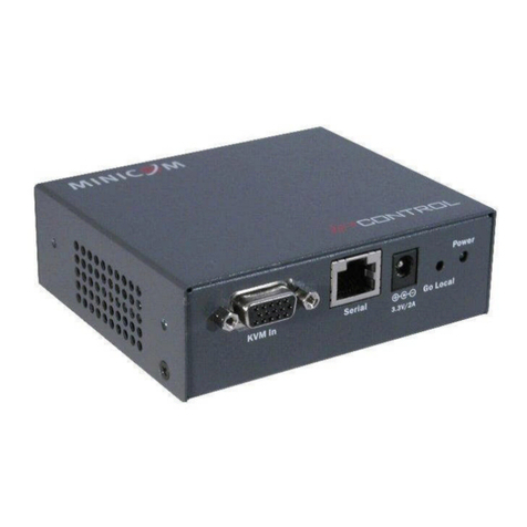
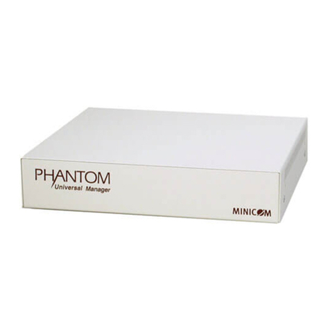
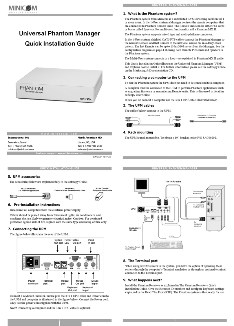
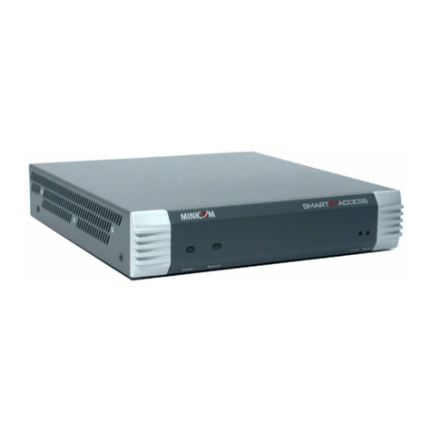
  9. Minicom 1SU70017 User manual

Minicom 1SU70017 User manual

2
IP Control - Quick Start Guide
1.
Introduction
To take advantage of the full range of features, we recommend
y
User Guide after performing the Quick Start procedure. It’s in
P
supplied CD or on our website www.minicom.com in the
Support
The IP Control extends your KVM (keyboard, video, mouse) fr
o
server over TCP/IP via LAN, WAN or Internet connection.
Now
monitor and manage your servers from wherever you are,
inside
organization. The IP Control is a cost-effective hardware
solution,
remote KVM access & control of a computer/server from the B
IO
independent of the OS. It is designed to connect to a single com
puter
switch to control multiple servers, over TCP/IP
commu
nication.
2. System
components
The IP Control system consists
of:
•
1 IP Control (p/n
1SU70017)
•
1 KVM cable (p/n
5CB00565)
•
1 RS232 cable (p/n
5CB00566)
•
1 Universal power adapter (p/n
5PSB0005)
•
Rack mount set (p/n
5AC00297)
QUICK START GUIDE
5. Rack mounting the IP
Control
The IP Control comes with screw holes on the side for easy
rack
figure
below.
Screw holes for
bracket
Figure 3 Screw holes for rack mounting
Use the L-shaped brackets and screws provided to mount the IP
rack or under a table top as illustrated below. The length of the
screws
connecting the brackets to the IP Control unit must not exceed
5
Screw L-shaped
brackets to 1 or both
sides of the unit
Figure 4 Connecting the L-shaped bracket
Figure 5 Connected to a rack Figure 6 Connected t
o
1111 W. 35th Street, Chicago, IL 60609 USA
www.tripplite.com/support
Copyright ©2012 Tripp Lite. All rights reserved.
Term Meaning
Target
server
The
comp
uter
Control.
Client
computer
The PC ru
n
Remote
Session
The proce
ss
conne
cted
IP C
The RS232 cable connects the IP
Control
Power Management units, routers,
etc.
3. The IP Control
unit
Figure 1 illustrates the front panel of
Ke
y
LAN
LAN
(Et
herne
connector
y
ou read
the softcopy
P
DF
format
on the
Support
section.
Figure 1 IP
For (optional) local access to the
connec
monitor and mouse to the above KV
M
Mbit Ethernet using the LAN
port.
o
m any computer
or
Now
you can
control,
inside
or outside
the
solution,
for
secure
IO
S level
-
KVM In
KVM In
puter
or to a
KVM
nication.
Connect a computer or KVM switch
to
cable. You press the Go Local
button
the computer
locally.
Connect an RS232 device to the S
erial
4. Pre-installation
guidelines
Place cables away from fluorescent
ligh
likely to generate electrical
noise.
rack
mounting,
see
IP C
6.
Terminology
Below are some terms and their me
anings
Control on a
server
screws
used
for
5
mm.
7. Client computer opera
t
Windows 2000 or higher, with Firef
ox
Linux with Firefox 3. 128 bit
encryption
8. Connecting the
sy
stem
Connect the Target Server / KVM
swit
1. Connect the single connector of
the
Control.
2. Connect the other end of the
KVM
/ KVM
switch.
3. Connect a Network cable to the
IP
your Network
switch.
4. Connect the power
adapter.
Figure 7 and Figure 8 illustrate the
connections
respectively, with the optional KVM
o
a table top
1111 W. 35th Street, Chicago, IL 60609 USA
www.tripplite.com/support
Copyright ©2012 Tripp Lite. All rights reserved.
3
uter
s/servers
that are accessed remotely via the
IP
nning a remote IP Control
session
ss
of accessing and controlling Target
Servers
cted
to IP Control from a User
workstation
IP C
ONTROL
Control
to Serial manageable devices such
as
etc.
the IP
Control.
y
board Monitor
herne
t) Mouse
IP
Control ports – side 1
connec
ted computer you connect a
keyboard,
M
ports. Connect the IP Control to a
10/100
Go
Local
Serial
Serial
button
Go Local
Power
3.3V/2A
Power Power
LED
Figure 2 IP Control ports – side 2
to
the KVM In port using the 1 to 3
CPU
button
to disconnect the remote session and
access
erial
port using the RS232
cable.
guidelines
ligh
ts, air conditioners, and machines that
are
1
IP C
ONTROL
anings
used in this
guide.
ting
system
ox
3 or Internet Explorer 6.0 or later
version.
encryption
support is
required.
stem
swit
ch to the IP Control as
follows:
the
KVM cable to the KVM In port of the
IP
KVM
cable to the KVM ports of the Target
Server
IP
Control LAN port and to an Ethernet port
on
connections
to a computer and KVM
switch
console.
All manuals and user guides at all-guides.com
all-guides.com

6
SD
MINICOM
IP CONTROL
QUICK START GUIDE
User
Internet / WAN / LAN
P110
MINICOM
LAN
KV M
In
Seri al
3.3V/2A
KVM
cable
Figure 7 IP Control connections to a computer
4
QUICK START GUIDE
Unit boots up
Device network setting
is set to obtain IP address from
DHCP Server
Yes
Is DHCP Server
present in the
connected LAN?
Every 5 minutes
No Device IP is:
192.168.0.155
Yes
IP address is assigned by the DHCP server
To access the configuration page of the unit, open Internet Ex
plo
/Firefox 3 or higher and type:
https://IPaddress
No Select Configuration
Default user: admin Default password: access
Set static IP
(deselect the DHCP
and set the IP)
Yes
The unit operates with the static IP address
Figure 9 Boot-up process
9.1 Static IP addresses for a number of units
Where you want to connect more than 1 IP Control to the same
network
is no DHCP server, or you want to use static IP addresses, do
the
Connect the IP Control units one at a time and change the static
unit before connecting the next
unit.
SD
MINICOM
IP CONTROL
over IP
IP C
User over
IP
Internet
P110
Target
PC
MINICOM
LAN
Figure 8 IP Cont
rol
9. Initial settings - Defau
l
The following sections provide
instructions
Control
unit.
See Figure 9 for an overview of the
boot
By default, IP Control boots with an
auto
DHCP (Dynamic Host Configuration
server provides a valid IP address,
ga
To identify the IP address, the IP
Control
the IP Control box. The device num
ber
If no DHCP server is found on the
network,
address
:
192.168.0.155.
Note! If a DHCP server later becom
e
from DHCP server. To keep the
static
full softcopy User
Guide.
IP C
10. Logging into the We
b
Complete the initial setup via the
Web
1. Open your Web
browser.
2. Type the IP Control system IP
address
The login page appears, see
Figure
No
plo
rer 6.0
Figu
r
3. in mode select Configuration
.
4. Type the default Administrator
user
lower
case).
5. Press Enter. The Web interface
opens
Figure
11.
network
and
there
the
following:
IP address of
each
Figure
11
To complete the initial setup and log
in
Guide on the su
ppli
http://www.minico
m
7
IP C
ONTROL
/ WAN /
LAN
KVM
switch
SERIA
MOUS
L
ESTATION 2 COMPUTER 5 COMPUTER 6 COMPUTER 7 COMPU TER 8
POWE
K P /2 MOUS
SCREE COMPUT ER
1
COMPUTER 2 COMPUTER
3
COMPUTER 4
R B S E
N
KVM
cable
ProL ia n t DL 360
9.1 - G B 10 k
ULT RA2 SC SI 9.1 - GB 1 0k
UL TRA 2 SC SI
ProL ia n t
DL3 60
9.1 - G B
10k
ULT RA2
SCSI
9.1 - GB 1 0k
UL TRA 2 SC SI
ProL ia n t DL 360
9.1 - G B
10k
ULT RA2
SCSI
ProL ia n t
DL3 60
9.1 - GB 1 0k
UL TRA 2 SC SI
9.1 - G B 10 k
ULT RA2 SC SI 9.1 - GB 1 0k
UL TRA 2 SC SI
ProL ia n t DL 360
9.1 - G B 10 k
ULT RA2 SC SI 9.1 - GB 1 0k
UL TRA 2 SC SI
ProL ia n t DL 360
9.1 - G B 10 k
ULT RA2 SC SI 9.1 - GB 1 0k
UL TRA 2 SC SI
Computer rack
rol
connections to a KVM switch
l
t IP
address
instructions
for setting the IP address for the
IP
boot
-up
process.
auto
matically assigned IP address from
a
Protocol) server on the network. The
DHCP
ga
teway address and subnet
mask.
Control
MAC address appears on the underside
of
ber
(D.N.) can also be found
there.
network,
IP Control boots with the static
IP
e
s available, the unit picks up the IP
settings
static
IP address, disable DHCP – explained in
the
5
IP C
ONTROL
b
interface
Web
configuration
interface:
address
- https://IP address/ - and press Enter
.
Figure
10.
r
e 10 Login page
user
name admin and password access
(both
opens
at the Network Configuration page.
See
11
Configuration page
in
to the web interface please see the softcopy
User
ppli
ed CD or on our
website
m
.com/supportuserguides.htm
201204189 • 933204_EN
All manuals and user guides at all-guides.com

This manual suits for next models

1

Other Minicom Switch manuals

Minicom 0SU70017 User manual

Minicom

Minicom 0SU70017 User manual

Minicom Minicom Smart 216 User manual

Minicom

Minicom Minicom Smart 216 User manual

Minicom 0SU52015 User manual

Minicom

Minicom 0SU52015 User manual

Minicom DX System User manual

Minicom

Minicom DX System User manual

Minicom Smart IP Access User manual

Minicom

Minicom Smart IP Access User manual

Minicom Smart CAT5 User manual

Minicom

Minicom Smart CAT5 User manual

Minicom PHANTOM MX II User manual

Minicom

Minicom PHANTOM MX II User manual

Minicom 0SU51068 User manual

Minicom

Minicom 0SU51068 User manual

Minicom 0SU52016 User manual

Minicom

Minicom 0SU52016 User manual

Minicom Minicom Smart 116 IP User manual

Minicom

Minicom Minicom Smart 116 IP User manual

Minicom PX User manual

Minicom

Minicom PX User manual

Minicom Remote Power Switch User manual

Minicom

Minicom Remote Power Switch User manual

Minicom 0SU70050 User manual

Minicom

Minicom 0SU70050 User manual

Minicom 0SU52015 User manual

Minicom

Minicom 0SU52015 User manual

Minicom Smart 108 IP User manual

Minicom

Minicom Smart 108 IP User manual

Minicom Smart CAT5 Switch 16 IP User manual

Minicom

Minicom Smart CAT5 Switch 16 IP User manual

Minicom Smart CAT5 User manual

Minicom

Minicom Smart CAT5 User manual

Minicom 0SU70033 User manual

Minicom

Minicom 0SU70033 User manual

Minicom RJ-45 User manual

Minicom

Minicom RJ-45 User manual

Minicom Smart 4 User manual

Minicom

Minicom Smart 4 User manual

Minicom 0SU51068 User manual

Minicom

Minicom 0SU51068 User manual

Minicom Minicom Smart 216 User manual

Minicom

Minicom Minicom Smart 216 User manual

Minicom Supervisor MU User manual

Minicom

Minicom Supervisor MU User manual

Minicom Switches User manual

Minicom

Minicom Switches User manual

Popular Switch manuals by other brands

ADTRAN NetVanta 1560-48-370W quick start

ADTRAN

ADTRAN NetVanta 1560-48-370W quick start

QEES 311-AQW-A1 quick guide

QEES

QEES 311-AQW-A1 quick guide

Action Star UK-2AA0-A-EL user guide

Action Star

Action Star UK-2AA0-A-EL user guide

Juniper QFX5220-128C quick start guide

Juniper

Juniper QFX5220-128C quick start guide

Gefen EXT-VGA-142N user manual

Gefen

Gefen EXT-VGA-142N user manual

Eneo IAM-5SE1004MUC user manual

Eneo

Eneo IAM-5SE1004MUC user manual

HPE 5920 series Command reference

HPE

HPE 5920 series Command reference

B&B UHR207 quick start guide

B&B

B&B UHR207 quick start guide

MFJ 1708SDR instruction manual

MFJ

MFJ 1708SDR instruction manual

Vetra Systems MegaTouch VIP-804-V-TS Series User instructions

Vetra Systems

Vetra Systems MegaTouch VIP-804-V-TS Series User instructions

Zonit Z-ATS-IND user guide

Zonit

Zonit Z-ATS-IND user guide

Extron electronics IN1508 instruction manual

Extron electronics

Extron electronics IN1508 instruction manual

H3C S5560S-SI installation guide

H3C

H3C S5560S-SI installation guide

Alcatel-Lucent 7210 SAS D Service guide

Alcatel-Lucent

Alcatel-Lucent 7210 SAS D Service guide

Lantronix SecureLinx SLK Series user guide

Lantronix

Lantronix SecureLinx SLK Series user guide

HP 316095-B21 - StorageWorks Edge Switch 2/24 user guide

HP

HP 316095-B21 - StorageWorks Edge Switch 2/24 user guide

Altronix HubWayLD8DS installation guide

Altronix

Altronix HubWayLD8DS installation guide

Atlona AT-OME-TX21-WP-E installation guide

Atlona

Atlona AT-OME-TX21-WP-E installation guide

manuals.online logo
manuals.online logoBrands
  • About & Mission
  • Contact us
  • Privacy Policy
  • Terms and Conditions

Copyright 2025 Manuals.Online. All Rights Reserved.