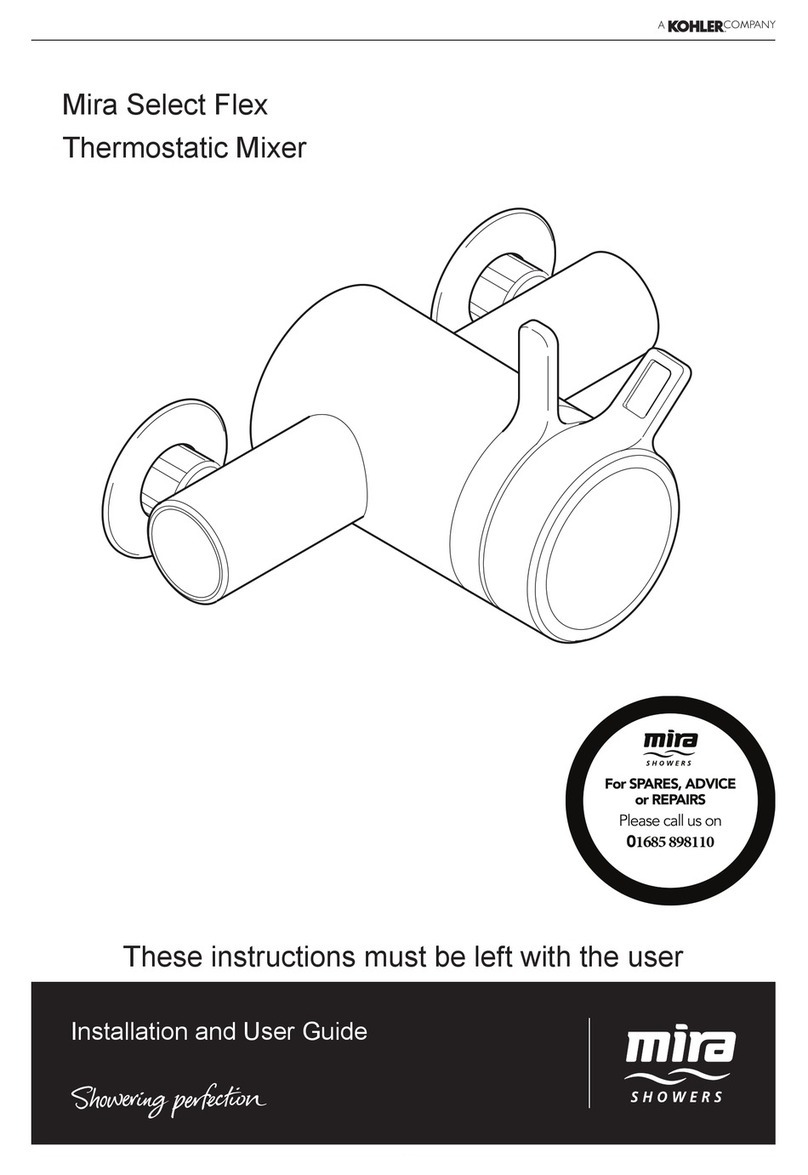
Mira Select Flex User manual
Other Mira Plumbing Product manuals
Mira
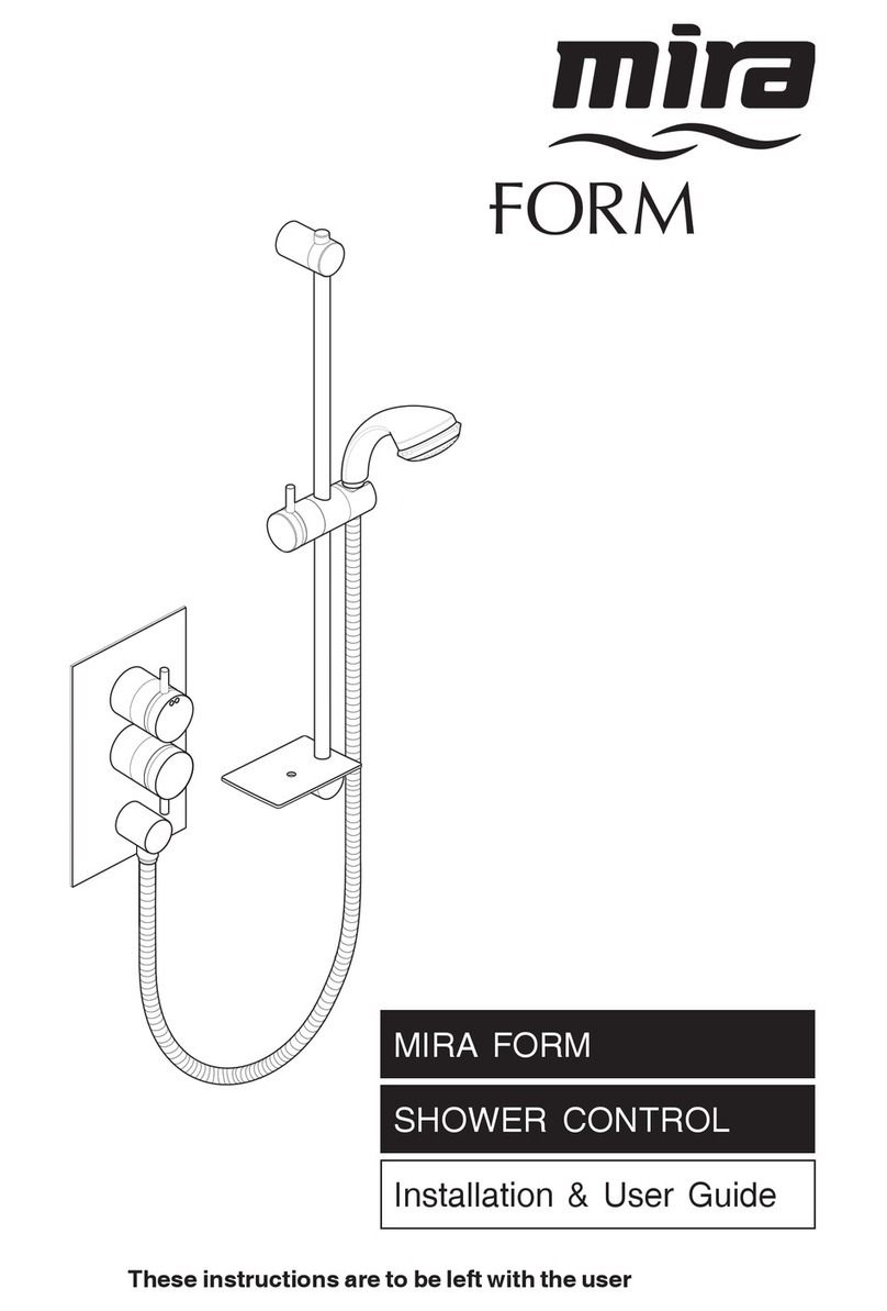
Mira FORM Operation manual
Mira
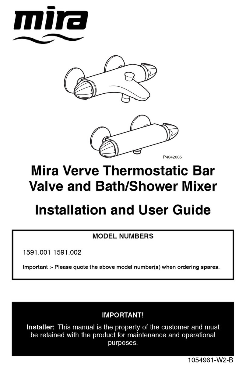
Mira 1591.001 User manual

Mira
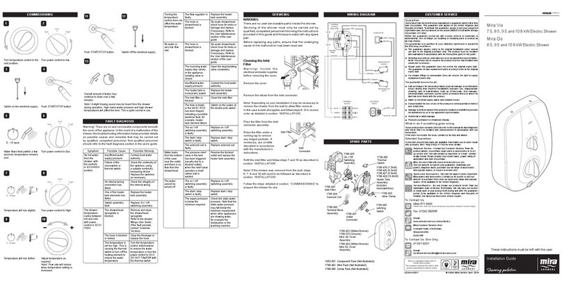
Mira Sport 7.5 User manual
Mira
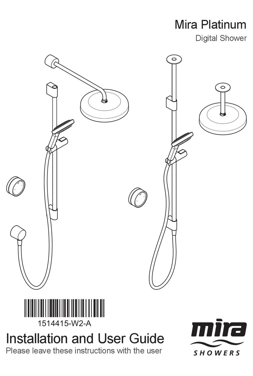
Mira Platinum User manual
Mira
Mira Select Flex LP-S User manual
Mira
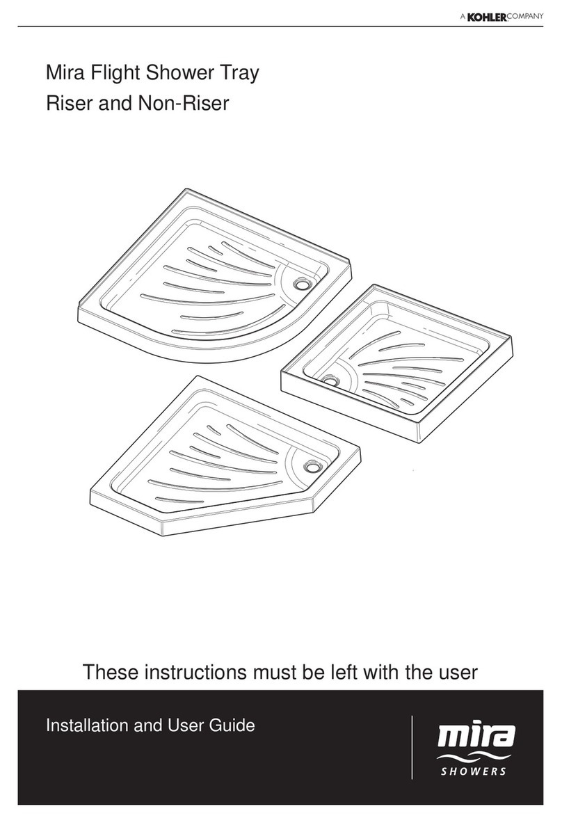
Mira Flight Shower Tray User manual

Mira
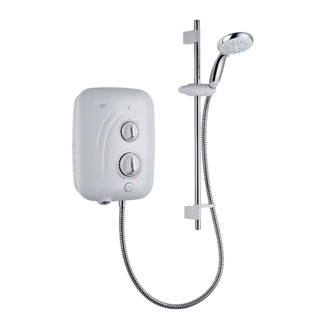
Mira Advance J97I User manual
Mira
Mira vigour User manual
Mira
Mira Flight Wall User manual
Mira
Mira Nectar User manual
Mira
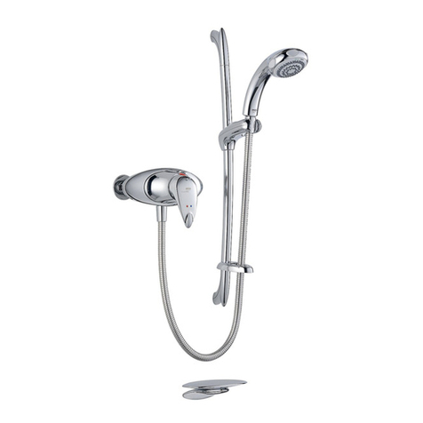
Mira Mode 1.1980.001 User manual
Mira
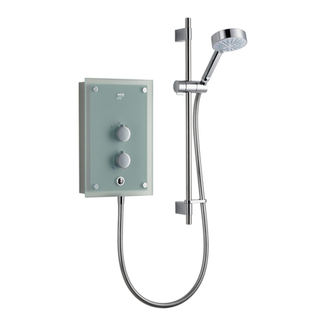
Mira COMBIFLOW User manual
Mira
Mira Azora User manual

Mira
Mira SHOWER FITTINGS Operation manual
Mira
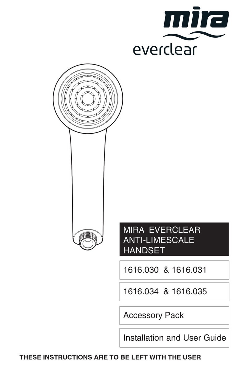
Mira everclear User manual

Mira
Mira Sport Max 1.1746.007 User manual

Mira
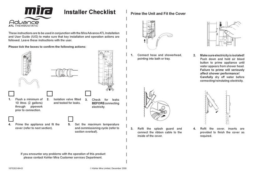
Mira Advance ATL J97A User manual
Mira
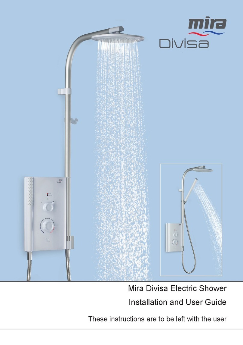
Mira Divisa User manual

Mira
Mira Extreme Thermostatic User manual
Mira
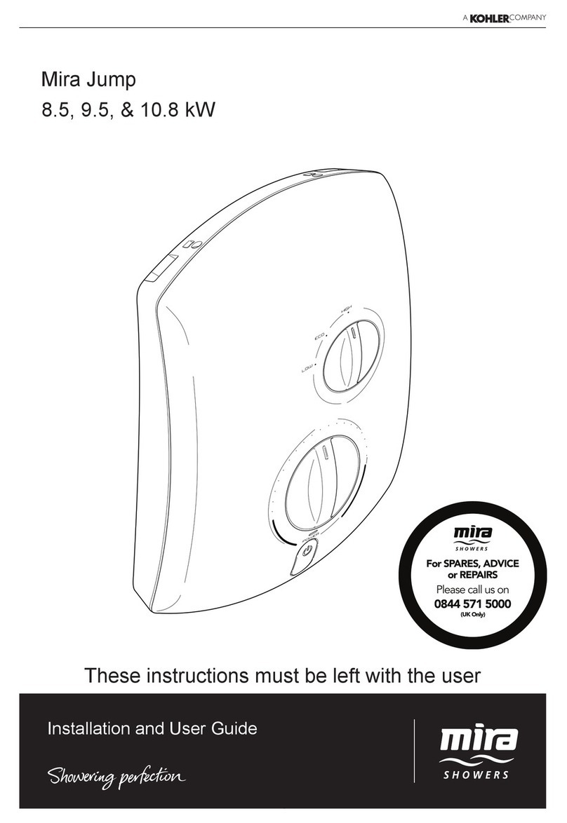
Mira Jump 96Va User manual
Popular Plumbing Product manuals by other brands

Moen
Moen SANI-STREAM 8797 manual

Grohe
Grohe Allure Brilliant 19 784 manual

Cistermiser
Cistermiser Easyflush EVO 1.5 manual

Kohler
Kohler Triton Rite-Temp K-T6910-2A installation guide

BEMIS
BEMIS FNOTAB100 Installation instruction

Hans Grohe
Hans Grohe ShowerTablet Select 700 13184000 Instructions for use/assembly instructions

Akw
Akw Stone Wash Basin Installation instructions manual

Enlighten Sauna
Enlighten Sauna Rustic-4 user manual

Moen
Moen ShowHouse S244 Series quick start guide

Sanela
Sanela SLWN 08 Mounting instructions

Franke
Franke 7612982239618 operating instructions

Heritage Bathrooms
Heritage Bathrooms Granley Deco PGDW02 Fitting Instructions & Contents List

Tres
Tres TOUCH-TRES 1.61.445 instructions

STIEBEL ELTRON
STIEBEL ELTRON WS-1 Operation and installation

Miomare
Miomare HG00383A manual

BELLOSTA
BELLOSTA revivre 6521/CR1 quick start guide

American Standard
American Standard Heritage Amarilis 7298.229 parts list

BorMann
BorMann Elite BTW5024 quick start guide
