Mitsubishi Electric Procon MOD-IP/50 User manual
Other Mitsubishi Electric Control Unit manuals
Mitsubishi Electric
Mitsubishi Electric MELSEC-L LD75P User manual
Mitsubishi Electric
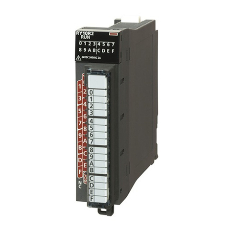
Mitsubishi Electric MELSEC iQ-R Series User manual
Mitsubishi Electric
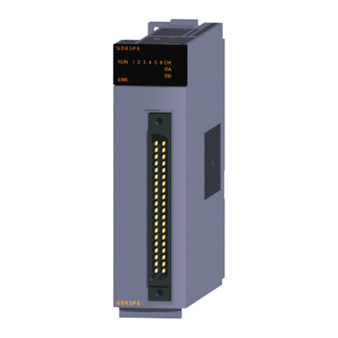
Mitsubishi Electric MELSEC Q Series User manual

Mitsubishi Electric
Mitsubishi Electric GT1055-QSBD Operating and maintenance instructions

Mitsubishi Electric
Mitsubishi Electric MELSEC QJ71PB92D User manual
Mitsubishi Electric
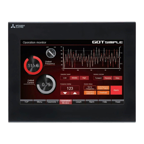
Mitsubishi Electric GOT SIMPLE GS2110-WTBD Operating and maintenance instructions

Mitsubishi Electric
Mitsubishi Electric MELSEC Q Series User manual

Mitsubishi Electric
Mitsubishi Electric GOT1000 GT1595-XTBA Operating and maintenance instructions

Mitsubishi Electric
Mitsubishi Electric MELSEC Q Series User manual

Mitsubishi Electric
Mitsubishi Electric NZ2FTGN User manual

Mitsubishi Electric
Mitsubishi Electric A1SJ71AP23Q User manual

Mitsubishi Electric
Mitsubishi Electric GT1695M-XTBA Operating and maintenance instructions
Mitsubishi Electric
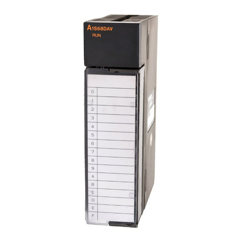
Mitsubishi Electric A1S68DAV User manual

Mitsubishi Electric
Mitsubishi Electric MELSEC Q Series User manual

Mitsubishi Electric
Mitsubishi Electric NZ2GF2B-60TCTT4 User manual

Mitsubishi Electric
Mitsubishi Electric Q68AD-G User manual

Mitsubishi Electric
Mitsubishi Electric MELSEC-QS Series User manual

Mitsubishi Electric
Mitsubishi Electric MELSEC iQ-R Series Installation and operating manual
Mitsubishi Electric
Mitsubishi Electric CC-Link IE Field NZ2GF12A-60IOLH8 User manual

Mitsubishi Electric
Mitsubishi Electric MELDAS 60 Series User manual
Popular Control Unit manuals by other brands

Festo
Festo Compact Performance CP-FB6-E Brief description

Elo TouchSystems
Elo TouchSystems DMS-SA19P-EXTME Quick installation guide

JS Automation
JS Automation MPC3034A user manual

JAUDT
JAUDT SW GII 6406 Series Translation of the original operating instructions

Spektrum
Spektrum Air Module System manual

BOC Edwards
BOC Edwards Q Series instruction manual

KHADAS
KHADAS BT Magic quick start

Etherma
Etherma eNEXHO-IL Assembly and operating instructions

PMFoundations
PMFoundations Attenuverter Assembly guide

GEA
GEA VARIVENT Operating instruction

Walther Systemtechnik
Walther Systemtechnik VMS-05 Assembly instructions

Altronix
Altronix LINQ8PD Installation and programming manual
