6
6. Electrical Work
Electrical work must be performed according to
the standards of each country. Never perform
connection by hand-twisting wires. Furthermore,
power lines must be connected inside a box and
box cover for rigid metal conduit
- Connection failure and faulty wiring work could
result in electric shock or fire.
CAUTION
Do not use the fan at other than the
rated voltage and frequency
- Failure to heed this warning may result
in fire or electric shock.
Be sure to install the ground wire
- Device failure and electric leakage
may cause electric shock.
WARNING
Perform connection after checking that the power supply
is correct. If the fan is operated with the wrong power
supply, the motor could burn out.
Be sure to install an electric leakage breaker.
Always ground the grounding terminal.
Circuit breakers conforming to EN60947-2 must be used.
Circuit breakers of which contact gaps are 3 mm or more
must be used. We recommended a Mitsubishi Electric
non-fuse circuit breaker (Model: NF32-SVF [Rated
current: 15 A, number of poles: 3]).
Connect the TN system to a 3-phase, 3-wire power supply.
The ground wire must always be connected.
For wires that are to be connected to the power cord
including the grounding wire, use electrical wire with a
copper conductor size of 0.75 mm2or above rated for a
voltage of 300 V between conductor and ground and a
voltage of 500 V, 7 A, or above between conductors.
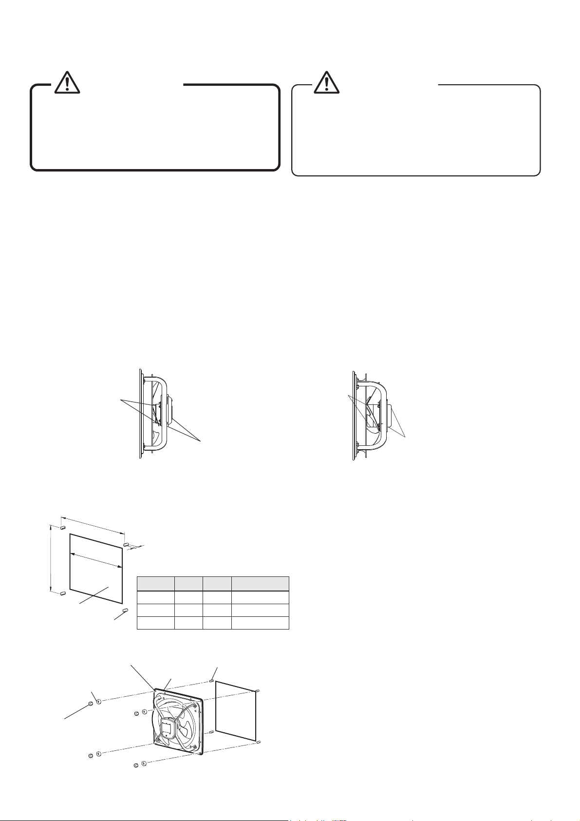
To connect to the power supply, install a metal electrical
conduit box near the fan installation area (within 0.8 m in
direct distance) and make connections inside the box.
Install another separate metal box, and connect the
circuit breaker and the electromagnetic switch together
inside the box.
Metal electrical
conduit box
Within
0.8 m
Fan
Motor
PE
L1
L2
L3
Connection Diagram
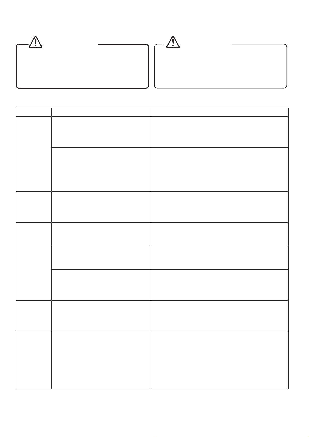
The terminals are labeled on the end of
the power cord as shown left. (Ground
is marked with this symbol: )
The conductor wire gauge for the power
cord is 18 AWG (Min 0.824 mm
2
).
Metal electrical conduit box (ventilator's power cord connection)
Electromagnetic
switch
Circuit
breaker
To protect against overload on the motor, use overload
protection equipment that employs a magnetic switch
(magnetic contact + thermal relay). Overload protection
equipment must be attached for every unit. A magnetic
switch conforming to EN60947-4-1 must be used.
We recommend a magnetic switch manufactured by
Mitsubishi (model: MSO-N10 (The specification is
described in Table 1)). The setting current value of
the magnetic switch must be set per the information
described in Table 2.
Table 2. Magnetic Switch Setting Current Value
Power Supply Model
Magnetic Switch Setting
Current Value (A)
Heater
Desig.
(A)
50Hz 60Hz
Three-phase
50/60Hz
200-220V
EF-35UDT-GL
1.3 1.4 1.3
EF-40UET-GL
2.3 2.7 2.5
EF-50UFT-GL
3.2 3.2 3.6
Three-phase
50/50/50/60/60Hz
380/400/415/400/440V
EF-35UDT40A-GL
0.70.650.7
EF-40UET40A-GL
1.2 1.2 1.3
EF-50UFT40A-GL
1.7 1.7 1.7
7. Trial Operation
After installation work, check the
following items.
1. Is the fan installed correctly?
2. Is not the power cord damaged?
3.
Has grounding work been performed correctly?
4. Is the power supply voltage correct?
Turn ON the breaker to perform trial operation.
5. Is not there abnormal vibration or noise?
(Where there is an abnormality, stop operation
and check the electrical work.)
6. Is the rotation direction reversed?
(If the rotation direction is reversed, switch two
of the three power wires.)
7DEOH6SHFL¿FDWLRQRI0621
Coil (kW) Auxiliary Contact
Standard (spec.)
220-220V 380-440V 500-550V
2.2 2.7 2.7 1a (1b)
Combination with Thermal Relay
Model Heater Desig.(A)
TH-N12
(KP)
0.12, 0.17, 0.24, 0.35, 0.5, 0.7, 0.9, 1.3,
1.7, 2.1, 2.5, 3.6, 5, 6.6, 9