E!
I1
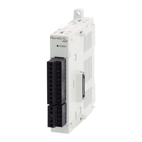
SYSTEM
BLOCK
DIAGRAM
POWER
LED
i
FX-2AD-PT
Analog
Blocs
.
..
..
.
..
.
.
..
.
..
..
.
.
...
...
..........
..
....
..
....
.
.
.
.
.
.
.
.
EXAMPLE
PROGRAM
Inthe program shown below, the FX-LAD-PT block occupies the position of speclalblocknumber2 (thatis
the thlrd closest block to the programmable controller). The averaging amountisfour. The averaged valuesin
degreesC of input channelsCHI and CH2 are stored respectivelyin data registersDO and Dl.
Block No.2 BFM#30
-,
(D2)
K1
1
ldentifi catlon code
1
When identification codeis K2020, M1
=
ON
When
(K2020)
=
(D2), M1
=
ON. i.e.
This initial step checks that the special function block placedat
positlon 2
IS
actuallyan FX-2AD-PT, i.e. its unit identlfication
number is2020 (BFM #30). This step
is
optional, but
it
providesa
software check that the system has been configured correctly.
!\g
K2
K29
K4M10K1
]
Transfertheerrorstatus
to
(M25
to
M10).
Block No.2 BFM#29
-.
(K4M10)
When errorisfound, M10
=
ON.
RepresentsbO BFM #29
~
monltor
M
10
This step provides optional monitoring ofthe FX-2AD-PT Error
Buffer Memory (#29).
If
there isan Error on the FX-2AD-PT, bitbO
of BFM #29
will
be set on. This can be readby this program Step,
and output asa bitdevice inthe FX programmable controller
(M3
In thls example). Additional Error devices can be outputin asimilar
manner,
i.e.
b10 BFM #29. (see below)
rc-7
K2
K29
K4M10K1
]
I
a
RepresentsbO BFM#29
I
a
Representsb10BFM #29
(K4)
-.
(BFM#l),(K4)
-.
(BFM #2)
K1
K4
K2]
Numberofsamples
IS
changedtofouronbothCH1
and CH2.
(BFM #5)
-,
(DO),
(BFM #60)
-.
(Dl)
K5
DO
K2
]
Transfertheaveragedtemperaturevalue in
‘c
to
the
data registers.
Thls stepis the actual reading of the FX-2AD-PT input channels.
It
isessenttally the only program step whichisneeded. The “TO”
instruction In this example, sets the input channels, CH1 and CH2,
to take the average readlng of four samples.
The “FROM” instruction reads the average temperatures (BMF
#5 and #6) for input channels CH1 and CH2 of the FX-2AD-PT.If
dwect temperature readlngs are required BFM
#9
and
#lo
should
be read instead, ex.
FNC78
K2
KQ
DO
K2
]
speciar
FX-PAD-PT
resUn
NO
of
blodtNo2
BFMnumbec
CleslhmUon
WMdSread
B
I1
DIAGNOSTICS
11
6.1
Prellmlnarvchecks
I
.
Check whether the inpuVoutput wirtng and/or extension cables areproperly connected on FX-2AD-PT
II
.
Check that the FX system configuration rules have not been broken,1.e. the number of speclal functlon
111.
Ensure that the correct operating range has been selected for the applicatlon.
IV
.Check that there
IS
no power overload onslther the 5V or 24V power sources, remember the loading on
an MPU or a powered extenslon unit vanes according
to
the number of extension blocks or special
function blocks connected.
analog special function block.
blocks doesnotexceed
8
and the total system
I10
IS
equal or less than
256,
I/O.
V.
Put the Main Processing Unlt (MPU) into RUN.
6.2
Errorchecklna
If the FX-2AD-PT specialfunction block does not seem to operate normally, checkthe followlng items.
0
Check the status ofthe POWER LED.
Llt
:
Theextensioncableisproperlyconnected.
Otherwise
:
Check the connection of the extension cable.
0
Check the external wiring.
0
Check the status of the “24V” LED (top rlght corner of the FXQAD-PT).
Lit
:
FX-PAD-PTis ON, 24VDCpowersource IS ON.
Otherwise
:
Possible 24V DC power failure,
If
ON possible FX-2AD-PT failure.
0
Check the status of the “A-D” LED (top right corner of the FX-PAD-PT).
Llt
:
A-D
conversion
IS
proceedlngnormally.
Otherwise
:
Check buffermemory #29 (error status).
If
any blts (bo, b2, b3) are ON, then thls
IS
why
the A-D LEDis OFF.
6.3
Checklnaspeclalfunctlonblocknumbers
Other speclal units or blocks that use
FROM0
commands, suchas analog input blocks, analog output
blocks and high-speed counter blocks, canbedirectly connected
to
the base unitof the FX programmable
controller or to the rlght side
of
other extension blocks or units. Each special blockisconsecutively numbered
from
0
to
7 beginning from the one closest
to
the base unlt. A maxlmum of eight speclal blockscan be
connected.
I1
EMC
CONSIDERATIONS
1
Electromagnetic compatibility or EMC must be considered before using the FX-PAD-PT.
Mltsubishi recommendthat thePT 100 sensors used, should befittedwith a formof shield or screenlng as
protection against EMC noise.
If
some form of cable protection is used, the “Shield” must be terminated at the
E]
terminals as shown
insection 2.0.
Because of the dellcate nature ofallanalog signals, failure
to
take good EMC precautlons could lead
to
EMC
nowinduced errors
;
up
to
f
10%
of actual values. ThisIS an absolute worst case flgure, users who do take
Guldellnes
for
the safoty
of
the user and ~rotoctlon
of
the
FX-PAD-PT
speclrl functlonblock
0
This manual has beenwritten
to
be used bytrained and competent personnel. This is defined
by the European directlvesfor machinery, low voltage and EMC.
0
If
indoubt at any stage durrng the Installation of the FX-PAD-PT always consult a professlonal
electrical engineerwho IS quallfiedandtrained
to
the local and natlonal standards.
If
In doubt
about the operatton
or
use
of
the FX-2AD-PT please consult the nearest Mttsubishi Electric
distributor.
Under on clrcumstances
will
Mltsubishl Electric be liable or responslble for any consequential
damage that may arlse asa result of the installation oruse of this equipment.
0
All
examples and diagrams shownInthis manual are Intended only as an atd
to
understandtng
the text, not
to
guarantee operation. Mitsubishi Electric
will
accept no responslbility for actual
use of the product basedon these illustrative examples.
I
I
Manual number
:
JY992D55701
Manual revision
:
A
Date
:
March 1996
A
goodprecautionscanexpectoperatlonwithinnormaltolerances.
A
MITSUBISHI
ELECTRIC
CORPORATION
EMCconsiderationsshouldincludeselectionofgoodqualltycables,goodroutlngofthosecablesawayfrom
HEAD
OFFICE
MlTSUBlSHl
ENKl
@LEG
WRUNWCH
TOKYO
(W
ELEX
ZWW
TOKYO
potential nolse sources.
Additionally It
IS
recommended that signal averaging
IS
used as this will reduce the effects of random noise
“spikes” .
HIMWI
WORKS
edo
CnlYODA
CY0
HIMEJI.
JAPAN
EffectiveMAR. 1996
Spectficatlons aresubject
to
change without notlce.
JY992D55701
A
