3. Name of Each Part and their settings
3.1 Name of Each Part
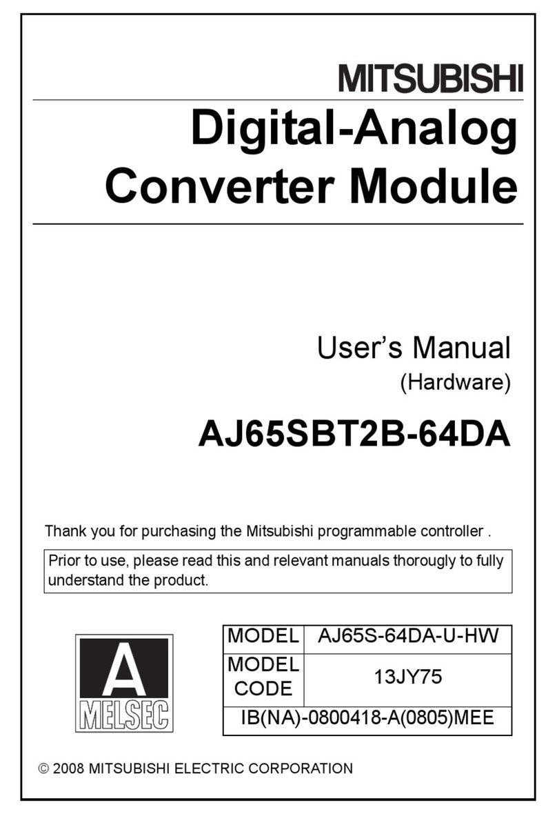
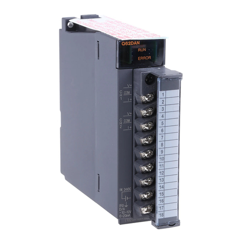
The name of each part and their settings in the AJ65BT-64AD are shown.
MITSUBISHI AJ65BT-64AD X10 X1
STATION NO.B RATE
CH. OFFSET GAIN. RESET
PW
RUN
L RUN
SD
RD
L ERR.
MELSEC
012
3
4
012
3
4
5
6
012
3
4
5
6
7
89
12
3
4
(Side)
2) 1) 9)
8) 7) 3) 4) 5) 6)
No. Name and
appearance
Description
1) Station number
setting switch
1) 10
1) 1
The station number for the AJ65BT-64AD is set in
the range 1 to 64.
(factory default: 00)
2) Transmission
baud rate setting
Setting
number
Transmission baud rate
switch 0 156kbps (factory default)
1 625kbps
2 2.5Mbps
3 5Mbps
4 10Mbps
Other than
0 to 4
Unusable.
(The L ERR. LED turns on, and results in a
communication error.)
3) Channel
selection switch
Selects the channel (1 to 4) to perform the offset and gain
adjustment. When a value other than 1 to 4 is selected, no
processing is performed. (factory default: 1)
4) OFFSET switch By turning this switch on during the test mode, the analog input
value at that time is stored in the AJ65BT-64AD as an offset value.
5) GAIN switch By turning this switch on during the test mode, the analog input
value at that time is stored in the AJ65BT-64AD as a gain value.
6) RESET switch The initialization of the I/O signals, remote register, and operation
processing is performed for the AJ65BT-64AD. By turning this switch
on, the AJ65BT-64AD initial data processing request flag turns on.
7) Operation status LED Name Description
display LED PW LED ON : Power supply ON
OFF : Power supply OFF
RUN LED Normal mode ON : Normal operation.
Flashing : Read/write data error
occurred.
OFF : 24VDC power supply
shutoff or watchdog
timer error occurred.
Test mode ON : Offset switch or gain switch
is ON.
OFF : Offset switch or gain switch
is OFF.
L RUN LED ON : Normal communication
OFF : Communication cutoff (time expiration error)
SD LED ON during data transmission
RD LED ON during data receive
L ERR. LED ON : Communication data error
Flashing : Communication data error
OFF : Normal communication
8) Terminal module 13579111315171921232527
2 4 6 8 101214161820222426
DA DG
DB SLD SLD(FG) TEST TEST
CH3
I+
CH1
I+
CH2
I+
CH3
V+
CH4
I+
+24V 24G FG1
AG
SLDSLD
CH1
V+
CH2
V+
CH4
V+
COM COM
COM COM
+24V 24G COM COM
COM COM
Test mode setting terminal: By short-circuiting between the
terminals, the test mode is started.
9) Analog input
range setting pin
C
D
A
B
Set the analog input range.
(Factory default : A)
* When using in the range 0 to 20mA, use D.
3.2 Offset/Gain Setting
When changing the I/O conversion characteristics, follow the procedure below.
RUN
CH
RUN OFFSET
V
V+
V+
COM
COM
A
I+
V
V+
V+
COM
COM
A
I+
OFF
ON
RUN GAIN
ON
Start
End
No
Yes
Set the setting pin to the range to use.
Short-circuit the test mode terminal
(between 8 to 10).
Set the "channel selection switch" to the
channel to be changed.
Set to the
channel to
be set.
Add the voltage or current that will be the
offset value.
For voltage
For current
For voltage
For current
Turn on the offset switch.
Add the voltage or current that will be the
gain value.
Turn on the gain switch.
Adjust other channels?
Release the test mode terminal
(between 8 to 10).
Remark
The offset value and gain value are as follows.
(a) The offset value is the analog input value (voltage or current) which a
minimum digital output value.
(b) The gain value is the analog input value (voltage or current) which a
maximum digital output value.
4. Loading and Installation
The following is explanations of the handling precautions and installation
environment which is common to modules when handling AJ65BT-64AD from
unpacking to installation.
For the details of loading and installation of the module, refer to User's Manual of
programmable controller CPU module to be used.
4.1 Handing Precautions
The precaution when handling the AJ65BT-64AD are described below:
(1) Because the case of the module is mad of resin, be careful not to drop it or
expose it to strong impact.
(2) Perform the tightening of the module mounting screws in the folowing range.
Screw position Tightening torque range
Module mounting screw (M4 screw) 78 to 118 N⋅cm
Terminal block terminal screw (M3.5 screw) 59 to 88 N⋅cm
Terminal block mounting screw (M4 screw) 78 to 118 N⋅cm
4.2 Installation Environment
Do not install the A series programmable controller in the following environments.
(1) Where the ambient temperature exceeds the 0 to 55°C range.
(2) Where the ambient humidity exceeds the 10 to 90 % RH range.
(3) Where condensation is produced by sudden temperature changes.
(4) Where corrosive or combustible gas is present.
(5) Where dust, iron powder and other conductive powder, oil mist, salt, or
organic solvents are prevalent.
(6) In direct sunlight.
(7) Where a strong electric or magnetic field is generated.
(8) Where vibration and shock may be applied directly to the module.
5. Data Link Cable Wiring
The wiring of the CC-Link dedicated cable which connects the AJ65BT-64AD and
the master module is described.
5.1 CC-Link dedicated cable connections
The CC-Link dedicated cable connections between the AJ65BT-64AD and
master module are as follows:
DA
DB
DG
SLD
FG
DA
DB
DG
SLD
FG
Terminate
resistor
DA
DB
DG
SLD
FG
Terminate
resistor
CC-Link dedicated
cable
CC-Link dedicated
cable
J65BT-64AD I/O module, etc.Master module side
Terminate
resistor
(Blue)
(White)
(Yellow)
6. Wiring
The precautions and module connection example for wiring are described.
6.1 Wiring Precautions
To obtain maximum performance from the functions of AJ65BT-64AD and
improve the system reliability, an external wiring with high durability against noise
is required.
The precautions when performing external wiring are as follows:
(1) Use separate cables for the AC and AJ65BT-64AD external input signals, in
order not to be affected by the AC side surge or conductivity.
(2) Do not bundle or place with load carrying wires other than the main circuit
line, hight voltage line, or programmable controller. Noises, surges, or
conductivity may affect the system.
(3) Place a one-point grounding on the programmable controller side for the
shielded line or shielded cable. However, depending on the external noise
conditions, it may be better have a grounding externally.
6.2 Module Connection Example
The connection examples for voltage input and current input are shown below:
(1) For voltage input
V+
I+
COM
SLD
*4 CH1
*1 Shield
*1 Shield
*3
*2
250
500k
500k
V+
I+
COM
SLD
CH4
*5
250
500k
500k
AG
FG1
Signal source 0 to ±10V
Signal source 0 to ±20mA
*1 Use a two-core twisted shield line for the power cable.
*2 Indicates the AJ65BT-64AD input resistor.
*3 For the current input, be sure to connect the (V+) and (I+) terminals.
*4 When noise or ripple occurs with the external cable, connect a condenser
with about 0.1 to 0.47μF25WV between the terminal V and COM.
*5 Always perform grounding for FG1. When there is a lot of noise, it may be
better to ground AG as well.
If the grounding wiring (grounding yes/no) is changed after the offset and
gain are set, perform the setting of the offset/gain values again.
7. External Dimension Diagram
(0.37)
2- 4.5 (0.18)
installation hole
Unit: mm (inch)
MITSUBISHI AJ 65BT-64AD X10 X1
STATION N O.B RATE
CH. OFFSET GAIN. RESET
PW
RUN
L RUN
SD
RD
L ERR.
MELSEC
012
3
4
012
3
4
5
6
012
3
4
5
6
7
89
12
3
4
NP
9.5
63(2.48)
142.9 (2.63)
151.9 (5.98)
56(2.2)
65(2.56)
Warranty
Mitsubishi will not be held liable for damage caused by factors found not to be
the cause of Mitsubishi; machine damage or lost profits caused by faults in the
Mitsubishi products; damage, secondary damage, accident compensation
caused by special factors unpredictable by Mitsubishi; damages to products
other than Mitsubishi products; and to other duties.
For safe use
yThis product has been manufactured as a general-purpose part for general
industries, and has not been designed or manufactured to be incorporated in a
device or system used in purposes related to human life.
yBefore using the product for special purposes such as nuclear power, electric
power, aerospace, medicine or passenger movement vehicles, consult with
Mitsubishi.
yThis product has been manufactured under strict quality control. However, when
installing the product where major accidents or losses could occur if the product
fails, install appropriate backup or failsafe functions in the system.
Country/Region Sales office/Tel
When exported from Japan, this manual does not require application to the Ministry
of Economy, Trade and Industry for service transaction permission.
Specifications subject to change without notice.
Printed in Japan on recycled paper.
HEAD OFFICE : TOKYO BUILDING, 2-7-3 MARUNOUCHI, CHIYODA-KU, TOKYO 100-8310, JAPAN
NAGOYA WORKS : 1-14, YADA-MINAMI 5-CHOME, HIGASHI-KU, NAGOYA, JAPAN
Country/Region Sales office/Tel
U.S.A Mitsubishi Electric Automation Inc.
500 Corporate Woods Parkway Vernon
Hills, IL 60061, U.S.A.
Tel : +1-847-478-2100
Brazil MELCO-TEC Rep. Com.e Assessoria
Tecnica Ltda.
Rua Correia Dias, 184,
Edificio Paraiso Trade Center-8 andar
Paraiso, Sao Paulo, SP Brazil
Tel : +55-11-5908-8331
Germany Mitsubishi Electric Europe B.V. German
Branch
Gothaer Strasse 8 D-40880 Ratingen,
GERMANY
Tel : +49-2102-486-0
U.K Mitsubishi Electric Europe B.V. UK
Branch
Travellers Lane, Hatfield, Hertfordshire.,
AL10 8XB, U.K.
Tel : +44-1707-276100
Italy Mitsubishi Electric Europe B.V. Italian
Branch
Centro Dir. Colleoni, Pal. Perseo-Ingr.2
Via Paracelso 12, I-20041 Agrate Brianza.,
Milano, Italy
Tel : +39-039-60531
Spain Mitsubishi Electric Europe B.V. Spanish
Branch
Carretera de Rubi 76-80,
E-08190 Sant Cugat del Valles,
Barcelona, Spain
Tel : +34-93-565-3131
France Mitsubishi Electric Europe B.V. French
Branch
25, Boulevard des Bouvets, F-92741
Nanterre Cedex, France
TEL: +33-1-5568-5568
South Africa Circuit Breaker Industries Ltd.
Private Bag 2016, ZA-1600 Isando,
South Africa
Tel : +27-11-928-2000
Hong Kong Mitsubishi Electric Automation
(Hong Kong) Ltd.
10th Floor, Manulife Tower, 169 Electric
Road, North Point, Hong Kong
Tel : +852-2887-8870
China Mitsubishi Electric Automation
(Shanghai) Ltd.
4/F Zhi Fu Plazz, No.80 Xin Chang Road,
Shanghai 200003, China
Tel : +86-21-6120-0808
Taiwan Setsuyo Enterprise Co., Ltd.
6F No.105 Wu-Kung 3rd.Rd, Wu-Ku
Hsiang, Taipei Hsine, Taiwan
Tel : +886-2-2299-2499
Korea Mitsubishi Electric Automation Korea
Co., Ltd.
1480-6, Gayang-dong, Gangseo-ku
Seoul 157-200, Korea
Tel : +82-2-3660-9552
Singapore Mitsubishi Electric Asia Pte, Ltd.
307 Alexandra Road #05-01/02,
Mitsubishi Electric Building,
Singapore 159943
Tel : +65-6470-2460
Thailand Mitsubishi Electric Automation (Thailand)
Co., Ltd.
Bang-Chan Industrial Estate No.111
Moo 4, Serithai Rd, T.Kannayao,
A.Kannayao, Bangkok 10230 Thailand
Tel : +66-2-517-1326
Indonesia P.T. Autoteknindo Sumber Makmur
Muara Karang Selatan, Block A/Utara
No.1 Kav. No.11 Kawasan Industri
Pergudangan Jakarta - Utara 14440,
P.O.Box 5045 Jakarta, 11050 Indonesia
Tel : +62-21-6630833
India Messung Systems Pvt, Ltd.
Electronic Sadan NO:III Unit No15,
M.I.D.C Bhosari, Pune-411026, India
Tel : +91-20-2712-3130
Australia Mitsubishi Electric Australia Pty. Ltd.
348 Victoria Road, Rydalmere,
N.S.W 2116, Australia
Tel : +61-2-9684-7777
Voltage Current
A 0 to 10V (0 to 20mA)*
B 1 to 5V 4 to 20mA
C -10 to 10V -20 to 20mA
D 0 to 5V 0 to 20mA
(2) For current input
