Mitsubishi CP910E(ID) User manual

COLOURVIDEOCOPYPROCESSOR
MODEL
CP910E(ID)
OPERATION MANUAL
THISOPERATIONMANUALISIMPORTANT
TOYOU.
PLEASEREADITBEFOREUSINGYOUR
COLOURVIDEOCOPYPROCESSOR.
ALARM SHEET PAPER S-VIDEO
This video copy processor complies with the requirements of the EC Directive
89/336/EEC, 73/23/EEC and 93/68/EEC.
The electro-magnetic susceptibility has been chosen at a level that gains proper
operation in residential areas, on business and light industrial premises and on
small-scale enterprises, inside as well as outside of the buildings. All places of
operation are characterised by their connection to the public low voltage power
supply system.

WARNING :
TO PREVENT FIRE OR SHOCK HAZARD, DO NOT EXPOSE THISAPPLIANCE TO
RAIN OR MOISTURE.
INFORMATION
This Class A digital apparatus complies with Canadian ICES-003.
Cet appareil numérique de la classe Aest conforme à la norme NMB-003 du Canada.
WARNING:
Use the AC power cord according to the recommendations as below so as not to interfere
with radio and television reception.
If you use other cables, it may cause interference with radio and television reception.
Case 1. Connect to the 120V receptacle of the room or the host equipment, in order to comply
with UL1950 and CAN/CSA C22.2 No. 950.
The AC power cord should be UL and CSAapproved and consist of type SVT, size
18AWG, shielded, length 1.8m or shorter cord with IEC320/C13 type, 125V 10A or
higher rating connector and NEMA 5-15 type, 125V 10A or higher rating.
Case 2. Connect to the 230V receptacle of the room or the host equipment, in order to comply
with EN60950.
Use the included AC power cord.

CAUTION
RISK OF ELECTRIC SHOCK
DO NOT OPEN
CAUTION: TO REDUCE THE RISK OF ELECTRIC SHOCK,
DO NOT REMOVE COVER (OR BACK)
NO USER-SERVICEABLE PARTS INSIDE
REFER SERVICING TO QUALIFIED SERVICE PERSONNEL.
The lightning flash with arrowhead symbol, within an
equilateral triangle, is intended to alert the user to the
presence of uninsulated "dangerous voltage" within the
product's enclosure that may be of sufficient magnitude to
constitute the risk of electric shock.
The exclamation point within an equilateral triangle is
intended to alert the user to the presence of important
operating and maintenance (servicing) instructions in the
literature accompanying the appliance.
NOTE:
This equipment has been tested and found to comply with the limits for a Class A digital
device, pursuant to Part 15 of the FCC Rules. These limits are designed to provide reasonable
protection against harmful interference when the equipment is operated in a commercial
environment. This equipment generates, uses, and can radiate radio frequency energy and,
if not installed and used in accordance with the instruction manual, may cause harmful
interference to radio communications. Operation of this equipment in a residential area is
likely to cause harmful interference in which case the user will be required to correct the
interference at his or her own expense.

1
CONNECTIONS ADJUSTMENTS
PRECAUTIONS FEATURES PREPARATION PRINTING TROUBLE-
SHOOTING OTHERS
CONTENTS
Contents................................................................................................ 1
Safety precautions ................................................................................ 2-4
Special features .................................................................................... 5
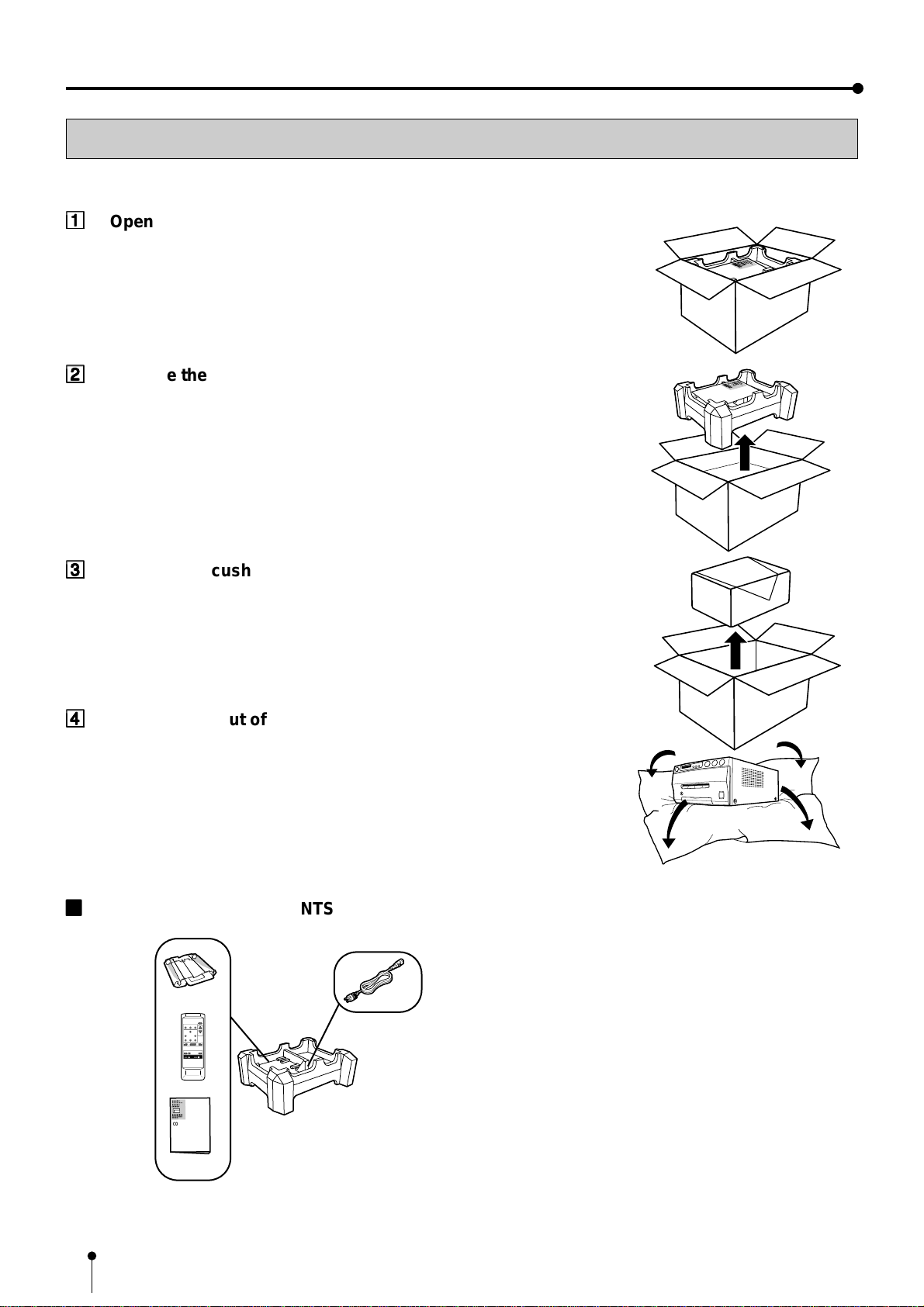
Unpacking ............................................................................................. 6
Features and functions ......................................................................... 7-9
Front panel............................................................................................. 7
Rear panel ............................................................................................. 8
Remote control unit................................................................................ 9
Connections .......................................................................................... 10
Connection with monitor and camera .................................................... 10
Before operation.................................................................................... 11-14
Paper sheet set...................................................................................... 11
Unlock the printing unit .......................................................................... 11
Installation of print paper........................................................................ 11-12
Installation of ink sheet .......................................................................... 12-14
Usage and keeping of paper sheet set .................................................. 14
Printing (Basic)...................................................................................... 15-18
Before printing........................................................................................ 15
Printing................................................................................................... 16-18
Display on the monitor screen ............................................................ 16
Memorizing and printing an image...................................................... 16
Selecting memorized image to print.................................................... 17
Image size and layout of memory pages ............................................ 17
Multiple copy or continuous printing.................................................... 18
Printing (Special)................................................................................... 19-21
Multi print ............................................................................................... 19
Separate print ........................................................................................ 19
External remote terminal 1..................................................................... 20
External remote terminal 2..................................................................... 20-21
Camera-IN terminal................................................................................ 21
Setting the functions (Menu chart) ........................................................ 22-23
Monitor display chart.............................................................................. 22-23
Adjustments & settings (MAIN MENU).................................................. 24-27
MAIN MENU items................................................................................. 24
Operating MAIN MENU.......................................................................... 24-25
COLOR ADJ (Color adjustment) ............................................................ 26
LAYOUT (Layout setting) ....................................................................... 26
PRINT (Print setting) .............................................................................. 27
MEMORY POSITION (Position setting) ................................................. 27
Adjustments & settings (SERVICE MENU)........................................... 28-33
SERVICE MENU items .......................................................................... 28
Operating SERVICE MENU................................................................... 28
SYSTEM SETUP (System setting) ........................................................ 29
GAMMAADJ (Gamma level setting) ...................................................... 29-30
LAYOUT2 (Layout setting 2) .................................................................. 30
ANALOG COLOR ADJ (Analog image adjustment)............................... 30
INPUT (Input signal setting) ................................................................... 30-31
OUTPUT (Output signal setting) ............................................................ 31
KEY SET (Button function setting) ......................................................... 31-32
RS232C SET (RS-232C setting)............................................................ 32
REMOTE SET (Remote signal setting).................................................. 32-33
PREVIOUS ERROR(Error display)........................................................ 33
Error messages..................................................................................... 34
Before calling for service....................................................................... 35-36
Overcoming paper jams ........................................................................ 37
Cleaning ................................................................................................ 38
Spec & options ...................................................................................... 39

2
SAFETY PRECAUTIONS
In the interest of safety, please observe the following precautions:
POWER REQUIREMENT
This Colour Video Copy Processor is designed to operate on 100V-120V AC 50/60Hz in U.S.A. and Canada, 220V-240V AC 50/
60Hz in Europe. Never connect to any outlet or power supply having a different voltage or frequency.
WARNING: THIS APPARATUS MUST BE EARTHED.
AVERTISSEMENT: CET APPAREIL DOIT ETRE MIS A LA TERRE.
PROTECTIVE MEASURES
IF ABNORMALITIES ARISE, ....
Use of the unit during emission of smoke or abnormal sounds (without adopting countermeasures) is dangerous. In such a
case, unplug the power cord from the source outlet immediately, and request maintenance service from the sales dealer.
NEVER INSERT ANY OBJECT INTO THE UNIT
Foreign objects of any kind inserted into this unit constitute a safety hazard and can cause extensive damage.
DO NOT PLACE ANYTHING ON THE COLOUR VIDEO COPY PROCESSOR
Heavy objects placed on the Colour Video Copy Processor can cause damage or obstruct proper ventilation.
PROTECT THE POWER CORD
Damage to the power cord may cause fire or shock hazard. When unplugging, hold by the plug only and remove carefully.
DO NOT PLACE WATER CONTAINERS ON THE UNIT
Do not place flower vases, and other water-holding containers on the device. If, for some reason, water seeps to the inside of
the unit, unplug the power cord from the source outlet, and contact the sales dealer. If used without corrective measures, the
unit may be damaged.
“In the interest of safety, avoid handling of liquids near the unit.”
DO NOT REMOVE THE CABINET
Touching internal parts is dangerous, besides, it may lead to malfunction. Contact the sales dealer to carry out internal checks
and adjustments. Before opening the cover for eliminating a jammed paper, etc., be sure to disconnect the power cord plug.
UNPLUG THE POWER CORD DURING A LONG ABSENCE
Turn off the MAIN power switch and unplug the power cord during a long absence.
WHEN TRANSPORTING THE UNIT
When transporting the unit, remove the ink cassette and paper. Make sure to slide the printing unit lock switch to the lock
position.
BE CAREFUL AROUND PRINT PAPER EXIT SLOT
Do not insert your hand or any material into the paper exit slot during printing.
Do not touch the cutter blade inside the paper exit slot.
Otherwise, your finger will be injured.
DO NOT TOUCH THE THERMAL HEAD
Do not touch your hand to the thermal head (located inside the unit).
The thermal head is heated to high temperature.
This may cause injury.
BE CAREFUL WITH THE PRINTING UNIT
Do not move the unit while the printing unit is sliding out. This may cause injury.
Be careful not to catch your finger in the printing unit while the printing unit is being retracted into the unit.
CONNECTION CABLES
Use the provided power cord.

3
CONNECTIONS ADJUSTMENTS
PRECAUTIONS FEATURES PREPARATION PRINTING TROUBLE-
SHOOTING OTHERS
INSTALLATION LOCATIONS
MAINTAIN GOOD VENTILATION
Ventilation slots and holes are provided on the sides of this unit. Place the unit on a hard and level surface and locate at least 4
inches (10cm) from walls to insure proper ventilation. When putting the unit on the system rack, take a space between the unit
and the back of the rack.
UNSUITABLE LOCATIONS
Avoid shaky places or hot-springs areas where hydrogen sulfide and acidic ions are likely to be generated.
PLACES WITH HIGH HUMIDITY AND DUST
Do not place the unit locations with high humidity and dust. They can cause extensive damage. Avoid places where unit is
likely to be exposed to oily fumes and vapors.
PLACES NOT LIKELY TO BE EXTREMELY HOT
Places exposed to direct sunlight, or near heating appliances can attain extremely high temperatures, which may deform the
cabinet, or can become a prime cause of damage.
PLACE THE UNIT ON A HORIZONTAL LEVEL
The unit is likely to be affected if it is placed in slanted conditions or in unstable places.
PROTECT AGAINST DEW FORMATION
In extremely cold regions, if the unit is moved quickly from an extremely cold place to warmer one, dew is likely to be formed.
If dew is formed, printing is not possible.
OPERATING AMBIENT TEMPERATURE RANGE
The operating ambient temperature range is 41°F - 104°F (5°C to 40°C), and humidity of 20% - 80%. When using the unit on
the system rack, be sure to keep this ambient temperature inside the rack.
FOR LONG OPERATING LIFE
UNSUITABLE MATERIALS FOR THE COLOUR VIDEO COPY PROCESSOR
Coat flaking and deformation are likely to occur if the unit is wiped with chemical dusters, benzine, thinner or any other solvent, if
rubber or PVC items are left in contact with the unit for extended duration, or if the unit is sprayed with insecticide.
CARE OF THE CABINET
Unplug and clean with a soft cloth slightly moistened with a mild soap and water solution. Allow to dry completely before
operating. Never use petroleum base solutions or abrasive cleaners.
HEAD ABRASION
The thermal head, like the video head, wears out. When it is abraded, it becomes hard to print out fine details of the picture. In
such a case, it is necessary to replace the thermal head. Consult with the sales dealer for replacing the head.
CONNECTING DEVICES
Read thoroughly “Operating Precautions”of the instruction booklets for the devices connected with the Colour Video Copy
Processor.
The power cord must be disconnected after printing is over.
CAUTION ON RELOCATING
When transporting this unit, make sure it is not likely to be subjected to impacts. They can be a prime cause for damage.
Further, make sure to disconnect the power cord from the power outlet, and the cables from the connected devices.

4
OTHER CAUTIONS
Dust or other foreign matter adhering to the print paper or the ink cassette, or deformation resulting from exposure to extremely low or high
temperatures could cause loss of colour, uneven colour or lines, or wrinkles in the print images.
NOTE:
YOUR UNDERSTANDING IS REQUESTED FOR THE LOSS OF IMAGES IN MEMORY DUE TO THE SUDDEN
OCCURRENCE OF A MALFUNCTION.
SAFETY PRECAUTIONS

5
CONNECTIONS ADJUSTMENTS
PRECAUTIONS FEATURES PREPARATION PRINTING TROUBLE-
SHOOTING OTHERS
SPECIAL FEATURES
2 PRINT SIZES ARE AVAILABLE ACCORDING TO THE PURPOSE
2 printing sizes, L size (max.110 x 160 mm) and S size (max.110 x 105 mm), are selectable.
HIGH SPEED PRINTING
Printing speed is approx. 44 seconds (in S size print). Using a rollpaper shortens the time for installing and removing.
LARGE CAPACITY OF PRINTING
Maximum number of printing (S size) is 130 printings per a roll paper. The large capacity of rollpaper printing reduces a time of
exchanges.
POSSIBLE OF A6 SIZE PRINTING IN HIGH QUALITY
High quality print is available in sublimation dye thermal method which is superior in repeatability of images. It also employs 256
gradients and about 16,700,000 colors in each YMC. A6 size printing helps its uses widely.
MULTI PRINT FOR VARIOUS DEMANDINGS
2, 4, 6 and 16 images of multi print are available. Several multi print modes are selectable according to demanding.
UNIQUE COLOR IMAGE CONTROL SYSTEM WITH THE IC CHIP BUILT IN INK SHEET ROLLS
By setting the supplied IC chip to ink cassette, the remaining of ink sheet can be displayed. It also controls the colors of the
printing images.
SUITABLE FOR PHOTO SYSTEM
(1) Input and output control signals from CAMERA-IN/Rear remote interfaces
(2) Image adjusting function such as contrast, brightness, depth etc. of printing image
(3) Capable of storing 3 kinds of setting and adjustment according to each using condition.
SPECIAL FEATURES

6
UNPACKING
UNPACKING
Take the unit out of the box by the following procedures. Make sure to check the contents.
11
11
1
Open the top of the box.
COLORVIDEO
COPYPROCESSOR
22
22
2
Remove the accessory box.
COLORVIDEO
COPY PROCESSOR
33
33
3
Remove the cushion above the unit.
44
44
4
Take the unit out of the box carefully.
Make sure to keep the unit horizontally.
Then, unwrap the packing.
22
22
2
ACCESSORY BOX CONTENTS
COLOURVIDEO
COPYPROCESSOR
PROG.
MENU
CLEAR
MONITOR
MEMORY
MEMORY
PAGE
STOP
SET
COLOR FIELD
ADJUST /FRAME
DISPLAY
PRINT
Q'ty
PRINT
Ink cassette
Wired remote control unit
Operation manual
Power cord
(CE cable)

7
CONNECTIONS PRINTING ADJUSTMENTS
PRECAUTIONS FEATURES PREPARATION OTHERS
TROUBLE-
SHOOTING
FEATURES & FUNCTIONS
FRONT PANEL
11
11
1
POWER BUTTON (INDICATOR)
Press to turn on power. Press again to turn off power.
When the power is turned on, the indicator illuminates.
22
22
2
ALARM INDICATOR
When this unit is overheated, this indicator goes on and
off. When other error occurs, it lights up.
33
33
3
SHEET ERROR INDICATOR
When an error concerning ink sheet occurs, this indicator
lights up.
44
44
4
PAPER ERROR INDICATOR
Whenan errorconcerning printpaperoccurs, thisindicator
lights up.
55
55
5
INPUT SIGNAL INDICATOR
This lamp always lights up.
66
66
6
MENU BUTTON
Press for color adjustment. The item will be switched in
order of;
SELECTCOLOR/B&W →BRT→CONT→R-SUB →G-SUB
→B-SUB→CENTER →CANCEL → SET → SELECT
COLOR/B&W. (Whenselecting B&W, R-SUB,G-SUB, B-SUB
change to Y-SUB, M-SUB, C-SUB.)
To go back to the normal screen, press
8
PLUS (+) button
while CANCEL or SET is selected.
See page 26.
77
77
7
MINUS (-) BUTTON
Press to decrease the value of each setting item. To set
the value, select SET with
6
MENU button and press
8
PLUS (+) button.
88
88
8
PLUS (+) BUTTON
Press to increase the value of each setting item. To set
the value, select SET with
6
MENU button and press this
button.
99
99
9
MONITOR BUTTON
Switches the display on the monitor. When this button is
pressed, the picture on the monitor screen switches
between the picture of the input signal (source image) and
the memorized image.
Whenpressing MEMORYbutton whileholding this button,
print paper will be fed and cut automatically, and the
mechanism will be initialized. Make sure to press
MONITOR button first, or a new image will be memorized.
AA
AA
A
MEMORY BUTTON
Press to memorize the image to be printed.
BB
BB
B
PRINT BUTTON
Press to print the image memorized by the MEMORY
button. The image on the monitor screen switches to the
picture of the input signal.
CC
CC
C
PRINT OUTLET
The printed paper comes out here.
Do not put any objects in front of the outlet.
DD
DD
D
OPEN BUTTON
Press to slide out the printing mechanism. Open the
mechanism to load paper and ink cassette or to clear a
paper jam.
EE
EE
E
TRAY
Holds the printed paper which was come out from the print
outlet. Press down the knob to pull out the tray. Make sure
to pull it out before using this unit.
FF
FF
F
REMOTE TERMINAL
Connects the remote control unit supplied.
GG
GG
G
PRINTING UNIT LOCK SWITCH
Locks the printing unit.
Shift the switch to the left (LOCK side) to lock and to the
right (UNLOCK side) to unlock.
This unit is locked when shipping. When transporting this
unit, make sure to lock the unit.
126
8
7
D
C
9AB
E
F
3
4
5
G
ALARM SHEET PAPER S-VIDEO

8
REAR PANEL
11
11
1
REMOTE TERMINAL 2 (MINI DIN 8 PIN)
Memorizingimages and printingis available bythe remote
signal inputted through this terminal. It is necessary to
make a circuit for remote control unit to use the function.
See pages 20-21.
22
22
2
REMOTE TERMINAL 1 (STEREO JACK)
Memorizing images is available by the remote signal
inputted through this terminal. It is necessary to make a
circuitfor remotecontrolunit touse thefunction. See page
20.
33
33
3
CAMERA-IN TERMINAL (25 PIN)
Use this terminal to connect this unit to a camera.
Do not connect with a personal computer.
Thisterminalcan notbeused when
4
S-VIDEOIN terminal
is used. See page 10 for connection.
REMOTE CAMERA-IN
S-VIDEO/IN S-VIDEO/OUT VIDEO OUT
AC IN
14
2 5
3
6
FEATURES & FUNCTIONS
44
44
4
S-VIDEO INPUT/OUTPUT TERMINAL
Use these terminals to connect to S-VIDEO signal
equipment. This terminal can not be used when
3
CAMERA-IN terminal is used. See page 10.
55
55
5
VIDEO SIGNAL OUTPUT TERMINAL
Use this terminal to connect this unit to VIDEO signal
equipment. See page 10.
66
66
6
AC LINE SOCKET
Connectsto theprovidedpowercord. Insertthe cordfirmly.

9
CONNECTIONS PRINTING ADJUSTMENTS
PRECAUTIONS FEATURES PREPARATION OTHERS
TROUBLE-
SHOOTING
REMOTE CONTROL UNIT
55
55
5
SET BUTTON
Press to display the items of the MENU. Repress to
memorizethe valuesand exitthe MENUmode. Seepages
22-23.
66
66
6
STOP BUTTONS
Press to cancel the printing process and start mechanical
initializing. Whenpressing thesebuttons during displaying
the main menu, the service menu will be displayed. When
pressing these buttons during stand-by status, the print
quantity is set to 1.
77
77
7
MEMORY PAGE BUTTON
Use to select the image memorized . The memory page is
switched every time this button is pressed. The selected
memory page mark illuminates.
88
88
8
PRINT BUTTON
Press to print the image memorized with the MEMORY
button.
99
99
9
PROGRAM BUTTON
Press the PROG. button to select between 3 types of user
presets. Functions previously set with the MENU can be
stored into one of 3 memories and recalled. Programs
cannot be changed during printing. The selected program
number is displayed for 3 seconds after pressing this
button. It may take longer to change the program.
AA
AA
A
{{
{{
{
,
}}
}}
}
,
[[
[[
[
,
]]
]]
]
BUTTONS
Use to set the MENU display. Values are increased/
decreased and the cursor position is changed with these
four buttons. See page 24 and 28.
BB
BB
B
MENU BUTTON
Press to display MAIN MENU used for various settings.
See pages 22-23.
CC
CC
C
CLEAR BUTTONS
Press to eliminate all or a part of memorized images.
DD
DD
D
MONITOR BUTTON
Press to switch the image of the input signal and the
memorized image being displayed.
EE
EE
E
MEMORY BUTTON
Use to memorize the image to be printed. The memorized
image is displayed on the monitor screen, and then the
image of the input signal is displayed.
11
11
1
COLOR ADJUST BUTTON
Press to switch black and white / color print.
22
22
2
FIELD/FRAME BUTTON (LINE ON/OFF)
Press to switch on/off of the frame showing the print area
on the display. This button is available when LINE of
MEMORY POSITION menu in MAIN MENU is set to ON.
33
33
3
DISPLAY BUTTON
Press to display the set condition on the monitor screen.
Press again to switch off the display.
44
44
4
PRINT QUANTITY
{{
{{
{
,
}}
}}
}
BUTTONS
Use to set the number of copies to be printed. Press
{
to
increasethe number and
}
to decrease thenumber. The
set number of copies is displayed on the monitor screen
for 3 seconds after pressing these buttons. See page 18.
Whenpressing
{
or
}
button during printing,the counter
becomes “1”and continuous printing is cancelled.
PROG.
MENU
CLEAR
MONITOR
MEMORY
MEMORY
PAGE
STOP
SET
COLOR FIELD
ADJUST /FRAME
DISPLAY
PRINT
Q' ty
9
A
B
C
D
E
3
4
6
5
7
8
PRINT
12

10
CONNECTIONS
The functions of this unit can be set by the menu screens displayed on the monitor.
Connect this unit with a monitor to check the images to be printed and the images stored in memory.
The following example shows the connection with monitor and camera.
Connect with the necessary signal equipment.
Make sure to turn off the power of the unit and connecting equipment before connection.
CONNECTION WITH MONITOR AND CAMERA
(EXAMPLE)
REMOTE CAMERA-IN
S-VIDEO/IN S-VIDEO/OUT VIDEO OUT
AC IN
To camera terminal
To CAMERA-IN
terminal
VCP
Camera
To S-VIDEO OUT terminal
S-VIDEO OUT
To S-VIDEO IN terminal
To VIDEO OUT terminal
VIDEO OUT
To VIDEO IN terminal
Monitor (PAL)
•Make sure to turn off the power before setting.
•Never connect CAMERA-IN terminal to a personal computer.

11
CONNECTIONS PRINTING ADJUSTMENTS
PRECAUTIONS FEATURES PREPARATION OTHERS
TROUBLE-
SHOOTING
BEFORE OPERATION
UNLOCK THE PRINTING UNIT
22
22
2
RELEASING THE PRINTING UNIT LOCK
11
11
1
Press down the knob to pull out the tray.
22
22
2
Shift the printing unit lock switch to the right (UNLOCK). (See page 7.)
PAPER SHEET SET
When using this unit for printing, make sure to use the following types of paper and ink sheet
set.
22
22
2
PAPER SHEET SET
Product name Ink sheet size No. of prints Usage
CK900S4P(HX)EU S size 130 Surface-laminated color print
CK900L4P(HX)EU L size 90 Surface-laminated color print
Before printing,
1. Unlock the printing unit. (See below)
2. Install the print paper and ink cassette. (pages 11-14)
INSTALLATION OF PRINT PAPER
Do not remove the seal on the print paper yet.
11
11
1
Insert the print paper roller with gear on the left.
Press the folder
1
as shown right, and set the print paper roller.
22
22
2
Set the other side of roller without gear.
2
1
1
Front side
Left side Right side
Gear Seal
1
2

12
INSTALLATION OF INK SHEET
Paper Paper Paper
22
22
2
INSTALLING THE INK SHEET
Load the ink cassette with the ink sheet roll before inserting the ink cassette into the
printer.
11
11
1
Put the ink sheet rollers with flat tops into the holes of ink
cassette.
Put the white roller (rolled with ink sheet) to the ink cassette first.
Then, put the colored roller (without ink sheet) to the ink cassette.
22
22
2
Put the other sides of rollers. Set IC at this time.
IC chip with the IC holder is attached to the ink sheet.
Set the IC holder to the ink cassette as shown right.
NOTE
•Do not remove the IC chip or IC holder from the ink sheet. Removal of the IC
will stop the printer from functioning correctly.
•Set the projected part of the IC holder to the correct position as shown below.
33
33
3
Remove the seal, and insert the edge of the print paper right
below the roller cover with arrow marks towards the front panel.
Make sure to insert the paper straight.
44
44
4
Feed the print paper through the paper outlet with your hand.
55
55
5
Pull the both side of the print paper to eliminate slack.
BEFORE OPERATION
Projected part
arrow marks
colored roller white roller
IC holder

13
CONNECTIONS PRINTING ADJUSTMENTS
PRECAUTIONS FEATURES PREPARATION OTHERS
TROUBLE-
SHOOTING
22
22
2
INSTALLING THE INK CASSETTE
11
11
1
Eliminate any slack of the ink sheet.
Hold the colored roller and turn the white roller.
22
22
2
Insert the ink cassette with the ink sheet into its compartment.
Put the ink cassette of the ink sheet with flat top side to each
1
. Then, set the other
side(with handle)as shownright. Whenexchanging theink cassetteand soon, remove
it by holding the handle.(See page 37.)
11
2
2
22
22
2
INSERT THE PRINTING UNIT
11
11
1
Push the printing unit until it is locked into place.
22
22
2
After plugging the power cord, press POWER button on the front
panel.
33
33
3
After the set conditions are displayed on the monitor, press
MEMORY button about 1 second with holding MONITOR button on
the front panel.
The print paper is automatically cut after feeding about 10 cm (4 inches).
44
44
4
Repeat the above step
33
33
3
once or twice.
Fingerprints and dust can be removed by feeding the print paper. The printing unit is
initialized.
NOTE
•Make sure to press MONITOR button first for operating
3
and
4.
Pressing MEMORY button first operates to memorize the images. When
exchanging the printing paper or ink cassette during using the unit, the
recorded images may be erased by pressing MEMORY button first.
•Do not feed the print paper more than 2 times. Doing so will not allow the
number of prints indicated on page 11 to be printed.
The installation of print paper and ink cassette is completed.
NOTE
An IC is built in the ink sheet. This is the IC chip, not a battery.
This IC can be thrown away as normal waste.

14
USAGE AND KEEPING OF PAPER SHEET SET
2
BEFORE PRINTING
•Fingerprints or dust on the paper’s surface may degrade print quality and cause paper jams.
Immediately after the paper is replaced, 2 images may be printed with a blank part due to
hand’s dust or oil. Refer to Pages 11-12.
•When print paper is rapidly transferred from a cool place to a hot place, vapor or dew will be
generated on the paper’s surface causing paper jams or degraded print quality. Leave the
print paper in the room to stabilize its temperature before using it.
•When print paper and ink sheet run out during printing, the printing operation stops and the
error messages such as “CHANGE PAPER”and “CHANGE INK”is displayed on the monitor.
Set new ink sheet or print paper. Refer to Page 34.
22
22
2
AFTER PRINTING
•When the printed paper is touched by a wet hand, the print may be discolored.
•Fading may occur if the print-face is exposed to organic chemical agents which may affect
print paper (e.g. alcohol, ester, ketone based).
•Fading will be accelerated upon contact with PVC-based materials (e.g. adhesive tapes,
rubber erasers, etc.).
22
22
2
STORAGE
•Avoid storing prints in direct sunlight or places with high humidity.
•Leaving the print paper in contact with PVC-based materials causes color of print paper to
come off and to be stained.
•Never store print paper in places that are close to heater, hot, humid or dusty.
Keep print paper in a place where;
Temperature : 5°C - 30 °C
Humidity : 20 % - 60 %RH
BEFORE OPERATION
NOTE
If the power is turned on and AUTO FEED&CUT on SYSTEM SETUP menu is set to ON,
“SET PAPER”disappears when print paper is set. (For AUTO FEED&CUT setting refer to
page29.) After insertinginksheet andclosing theprinting unit,the print paperis automatically
fed and cut twice.
NOTE
Take the print paper one by one after completing printing. Pull out the tray completely when
using it. If you fail to do so, paper jamming may occur.
Put the tray back when finishing printing.

15
CONNECTIONS PRINTING ADJUSTMENTS
PRECAUTIONS FEATURES PREPARATION OTHERS
TROUBLE-
SHOOTING
MAIN MENU
COLOR [
]
]
INPUT S-VIDEO
LAYOUT [
]
]
PRINT [
]
]
MEMORY POSITION [
]
]
SAVE PRG 1 / 2 / 3 / CANCEL
LAYOUT
MODE AUTO/S
IMAGES 1/2/4/4D/6/16
SIZE : USER
TOP : 0 (0 - -63)
BOTTOM : 0 (0 - -63)
LEFT : 0 (0 - -63)
RIGHT : 0 (0 - -63)
LAYOUT
MODE AUTO/S
IMAGES 1/2/4/4D/6/16
SIZE : USER
TOP : 0 (0 - -63)
BOTTOM : 0 (0 - -63)
LEFT : 0 (0 - -63)
RIGHT : 0 (0 - -63)
MAIN MENU
COLOR [
]
]
INPUT S-VIDEO
LAYOUT [
]
]
PRINT [
]
]
MEMORY POSITION [
]
]
SAVE PRG 1 / 2/3/CANCEL
PRINTING (BASIC)
BEFORE PRINTING
PROG.
MENU
CLEAR STOP
SET
COLOR FIELD
ADJUST /FRAME
DISPLAY
PRINT
Q' ty
22
22
2
SELECTING PRINT SIZE AUTO/S
•AUTO is selected for initial setting.
•Select “AUTO”or “S”according to the print size.
AUTO : Selects print size automatically according to the installed ink sheet.
S : Selects S size regardless of the installed ink sheet.
•The print size can be set on the menu displayed on the monitor screen.
•Unless the ink sheet size is changed, it is not necessary to select the print size every
time.
11
11
1
Press MENU button and MAIN MENU is displayed.
22
22
2
Press
{{
{{
{
,
}}
}}
}
button to select “LAYOUT”.
33
33
3
Press
]]
]]
]
button.
•LAYOUT is displayed.
•Normally, “MODE”is selected when opening LAYOUT. When other item is
selected, press
{
or
}
button to select “MODE”.
44
44
4
Press
[[
[[
[
,
]]
]]
]
button to select “AUTO”or “S”.
•Select “AUTO”for normal setting. Select “S”to print S size with L size ink sheet.
55
55
5
Press SET button.
•MAIN MENU is displayed.
•“SAVE PRG 1/2/3/CANCEL”is selected.
•This menu lets you select a user program memory (1-3) to store your new settings.
66
66
6
Press
[[
[[
[
,
]]
]]
]
button to select one of the user memory (1-3) to
memorize the setting.
The program is replaced. In case of keeping the stored program, do not select the user
memory number in which the setting is stored.
When CANCEL is selected, the settings are not memorized.
77
77
7
Press SET button.
The source image is displayed.
The print size setting is completed.
MAIN MENU
COLOR [
]
]
INPUT S-VIDEO
LAYOUT [
]
]
PRINT [
]
]
MEMORY POSITION [
]
]
SAVE PRG 1 /2/3/CANCEL
MAIN MENU
COLOR [
]
]
INPUT S-VIDEO
LAYOUT [
]
]
PRINT [
]
]
MEMORY POSITION [
]
]
SAVE PRG 1 / 2 / 3 / CANCEL

16
PRINTING
22
22
2
DISPLAY ON THE MONITOR SCREEN
The setting will be displayed on the monitor screen as shown below.
PRINTING (BASIC)
1 This mark illuminates when the memorized image is displayed on the monitor.
When an image from the input signal is displayed, this mark does not illuminate. To
switch the mode, press MONITOR button.
2 These marks show the pages, A and B.
The upper mark shows page A and lower shows B. The mark of the selected page
illuminates. To switch the page, press MEMORY PAGE button.
3 This mark shows color print or black and white print. When black and white print is
selected by the B&W of COLOR in MAIN MENU, the mark illuminates.
4 These marks show the multi image print mode.
From the top to bottom, the mark indicates 1, 2, 4, 6, 16-multi image print.
When 4D mode is selected, the third mark and the marks No. 2 (page numbers)
illuminate. The replacing page illuminates in red.
22
22
2
MEMORIZING AND PRINTING AN IMAGE
(When Page Increment is set OFF in the INCREMENT menu)
11
11
1
Press MONITOR button to select “MEMORY”on the display.
•The contents of the current memory page will be displayed.
•If you do not want to write over the current image, press MEMORY PAGE button to
select another page.
22
22
2
Press MONITOR button to select “LIVE ”.
33
33
3
When the desired image is shown on screen, press MEMORY
button.
•The image will be captured and displayed on the screen.
44
44
4
Press PRINT button.
1
2
3
4
(example)

17
CONNECTIONS PRINTING ADJUSTMENTS
PRECAUTIONS FEATURES PREPARATION OTHERS
TROUBLE-
SHOOTING
PRINT EXAMPLE
1
2
4
6
16
MULTI
4D
22
22
2
IMAGE SIZE AND LAYOUT OF MEMORY PAGES
22
22
2
SELECTING MEMORIZED IMAGE TO PRINT
11
11
1
Press MONITOR button to select “MEMORY”on the display.
•The contents of the current memory page will be displayed.
22
22
2
Press the MEMORY PAGE button to select page A or B.
33
33
3
Press the PRINT button.
This manual suits for next models
1
Table of contents
Other Mitsubishi Media Converter manuals

Mitsubishi
Mitsubishi AJ65SBT-64AD User manual

Mitsubishi
Mitsubishi MELSEC A1S64AD User manual

Mitsubishi
Mitsubishi AJ65SBT-62DA User manual

Mitsubishi
Mitsubishi Q62DAN User manual

Mitsubishi
Mitsubishi AJ65SBT-64AD User manual

Mitsubishi
Mitsubishi AJ65SBT2B-64DA User manual

Mitsubishi
Mitsubishi CP800E User manual

Mitsubishi
Mitsubishi MELSEC-A AJ65VBTCU-68DAVN User manual

Mitsubishi
Mitsubishi Q62DAN User manual

Mitsubishi
Mitsubishi AJ65SBT-62DA User manual