Mitsubishi CP800E User manual

This video copy processor complies with the requirements of the EC Directive
89/336/EEC, 73/23/EEC, 93/42/EEC and 93/68/EEC.
The electro-magnetic susceptibility has been chosen at a level that gains
proper operation in residential areas, on business and light industrial premises
and on small-scale enterprises, inside as well as outside of the buildings. All
places of operation are characterised by their connection to the public low
voltage power supply system.
COLOURVIDEOCOPYPROCESSOR
MODEL
CP800E
OPERATION MANUAL
THISOPERATIONMANUALISIMPORTANT
TOYOU.
PLEASEREADITBEFOREUSINGYOUR
COLOURVIDEOCOPYPROCESSOR.
POWER
OPEN
REMOTE
MEMORY PRINT
MONITOR
CP800

CONTENTS
Contents
Safety precautions ................................................................................ 1-3
Special features .................................................................................... 4
Features and functions.......................................................................... 5-7
Front panel ............................................................................................. 5
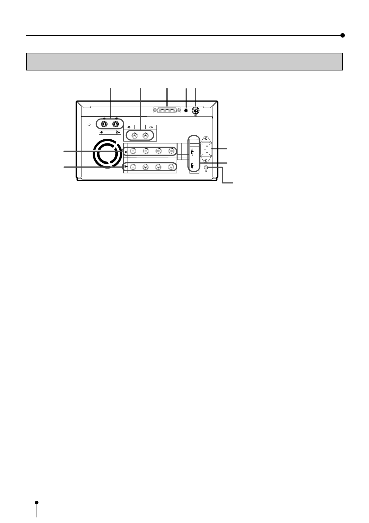
Rear panel ............................................................................................. 6
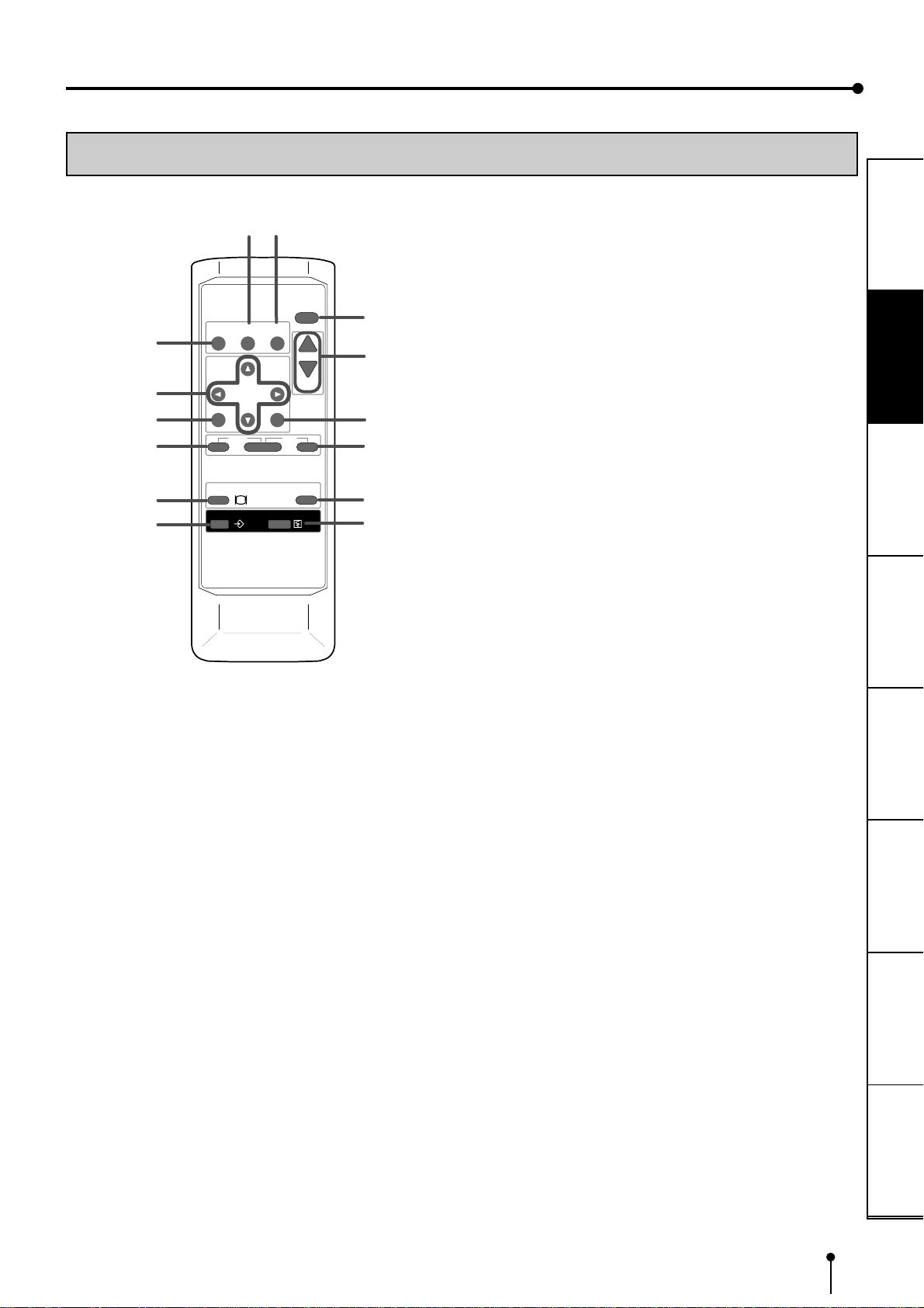
Remote control....................................................................................... 7
Connections .......................................................................................... 8-13
Connection with a monitor ..................................................................... 8-10
Connection with video or S-video signal equipment .............................. 10
Connection with RGB analog signal equipment..................................... 11
Connection with RS-232C equipment.................................................... 12-13
Before operation.................................................................................... 14-18
Paper sheet set and ink sheet................................................................ 14
Removing transport screw and protective cushion ................................ 14-15
Installation of print paper........................................................................ 15-16
Installation of ink sheet .......................................................................... 16-17
Usage and keeping of paper sheet set .................................................. 18
Printing (Basic)...................................................................................... 19-25
Before printing........................................................................................ 19-21
Memory print .......................................................................................... 22-25
Memorizing and printing an image...................................................... 22
Selecting memorized image to print.................................................... 23
Image memorizing with page increment set on .................................. 23
Image size and number of memory pages.......................................... 24
Multiple copy or continuous printing.................................................... 25
Printing (Special)................................................................................... 26-31
Multi print ............................................................................................... 26-27
Separate print ........................................................................................ 28
External remote terminal 1..................................................................... 29
External remote terminal 2..................................................................... 30-31
Setting the functions (Menu chart) ........................................................ 32-35
Monitor display chart.............................................................................. 32-33
LCD display chart................................................................................... 34-35
Adjustments & settings (MAIN MENU).................................................. 36-44
MAIN MENU items................................................................................. 36
Operating MAIN MENU.......................................................................... 36-37
COLOR ADJ (Colour adjustment).......................................................... 38
ANALOG ADJ (Analog image adjustment) ......................................... 38
INPUT (Signal selection)........................................................................ 38
ADDITIONAL (Special print setting)....................................................... 39
PRINT (Print setting) .............................................................................. 40-41
COMMENT (Making a comment)........................................................... 42-43
SIZE/TIMING (Setting size and timing) .................................................. 43-44
Adjustments & settings (SERVICE MENU)........................................... 45-50
SERVICE MENU items .......................................................................... 45
Operating SERVICE MENU ................................................................... 45
KEY SET (Setting functions of buttons) ................................................. 46-47
SIGNAL SET1(Signal setting display).................................................... 47-48
SIGNAL SET2(Signal setting display).................................................... 48
PRINT SET (Print setting display).......................................................... 48-49
SYSTEM SET(System setting display) .................................................. 49
REMOTE SET(Remote signal setting display)....................................... 49-50
PREVIOUS ERROR(Error display) ........................................................ 50
Adjusting image without using remote control ....................................... 50
Error messages..................................................................................... 51
Before calling for service....................................................................... 52-53
Overcoming paper jams ........................................................................ 54
Cleaning ................................................................................................ 55-56
Spec & options ...................................................................................... 57

1
CONNECTIONS ADJUSTMENTS
PRECAUTIONS FEATURES PREPARATION PRINTING TROUBLE-
SHOOTING OTHERS
In the interest of safety, please observe the following precautions:
POWER REQUIREMENT
This Colour Video Copy Processor is designed for operation on 220-240V, 50HzAC. Never connect to any outlet or power
supply having a different voltage or frequency.
WARNING: THIS APPARATUS MUST BE EARTHED.
AVERTISSEMENT: CET APPAREIL DOIT ETRE MIS A LA TERRE.
PROTECTIVE MEASURES
IF ABNORMALITIES ARISE, ....
Use of the unit during emission of smoke or abnormal sounds (without adopting countermeasures) is dangerous. In such a
case, unplug the power cord from the source outlet immediately, and request maintenance service from the sales dealer.
NEVER INSERT ANY OBJECT INTO THE UNIT
Foreign objects of any kind inserted into this unit constitute a safety hazard and can cause extensive damage.
DO NOT PLACE ANYTHING ON THE COLOUR VIDEO COPY PROCESSOR
Heavy objects placed on the Colour Video Copy Processor can cause damage or obstruct proper ventilation.
PROTECT THE POWER CORD
Damage to the power cord may cause fire or shock hazard. When unplugging, hold by the plug only and remove carefully.
DO NOT PLACE WATER CONTAINERS ON THE UNIT
Do not place flower vases, and other water-holding containers on the device. If, for some reason, water seeps to the inside of
the unit, unplug the power cord from the source outlet, and contact the sales dealer. If used without corrective measures, the
unit may be damaged.
“In the interest of safety, avoid handling of liquids near the unit.”
DO NOT REMOVE THE CABINET
Touching internal parts is dangerous, besides, it may lead to malfunction. Contact the sales dealer to carry out internal checks
and adjustments. Before opening the cover for eliminating a jammed paper, etc., be sure to disconnect the power cord plug.
UNPLUG THE POWER CORD DURING A LONG ABSENCE
Turn off the MAIN power switch and unplug the power cord during a long absence.
WHEN TRANSPORTING THE UNIT
When transporting the unit, remove the sheet cartridge and paper from the paper cassette, and insert the protective cushion into
its compartment. Make sure to screw the printing unit down.
BE CAREFUL AROUND PRINT PAPER EXIT SLOT
Do not insert your hand or any material into the paper exit slot during printing.
Do not touch the cutter blade inside the paper exit slot.
Otherwise, your finger will be injured.
DO NOT TOUCH THE THERMALHEAD
Do not touch your hand to the thermal head (located inside the unit).
The thermal head is heated to high temperature.
This may cause injury.
BE CAREFUL WITH THE PRINTING UNIT
Do not move the unit while the printing unit is sliding out. This may cause injury.
Be careful not to catch your finger in the printing unit while the printing unit is being retracted into the unit.
CONNECTION CABLES
Use the provided power cord and the composite video signal cable. When connecting the unit with an equipment with RS-232C
interface, use the RS-232C crossover cable.
SAFETY PRECAUTIONS

2
SAFETY PRECAUTIONS
INSTALLATION LOCATIONS
MAINTAIN GOOD VENTILATION
Ventilation slots and holes are provided on the top, sides and bottom of this unit. Place the unit on a hard and level surface and
locate at least 10cm from walls to insure proper ventilation. When putting the unit on the system rack, take a space between the
unit and the back of the rack.
UNSUITABLE LOCATIONS
Avoid shaky places or hot-springs areas where hydrogen sulfide and acidic ions are likely to be generated.
PLACES WITH HIGH HUMIDITY AND DUST
Do not place the unit locations with high humidity and dust. They can cause extensive damage. Avoid places where unit is likely
to be exposed to oily fumes and vapours.
PLACES NOT LIKELY TO BE EXTREMELY HOT
Places exposed to direct sunlight, or near heating appliances can attain extremely high temperatures, which may deform the
cabinet, or can become a prime cause of damage.
PLACE THE UNIT ON A HORIZONTAL LEVEL
The unit is likely to be affected if it is placed in slanted conditions or in unstable places.
PROTECT AGAINST DEW FORMATION
In extremely cold regions, if the unit is moved quickly from an extremely cold place to warmer one, dew is likely to be formed.
If dew is formed, printing is not possible.
OPERATING AMBIENT TEMPERATURE RANGE
The operating ambient temperature range is 41°F - 104°F (5°C to 40°C), and humidity of 20 - 80%. When using the unit on the
system rack, be sure to keep this ambient temperature inside the rack.
FOR LONG OPERATING LIFE
UNSUITABLE MATERIALS FOR THE COLOUR VIDEO COPY PROCESSOR
Coat flaking and deformation are likely to occur if the unit is wiped with chemical dusters, benzine, thinner or any other solvent, if
rubber or PVC items are left in contact with the unit for extended duration, or if the unit is sprayed with insecticide.
CARE OF THE CABINET
Unplug and clean with a soft cloth slightly moistened with a mild soap and water solution. Allow to dry completely before
operating. Never use petroleum base solutions or abrasive cleaners.
HEAD ABRASION
The thermal head, like the video head, wears out. When it is abraded, it becomes hard to print out fine details of the picture. In
such a case, it is necessary to replace the thermal head. Consult with the sales dealer for replacing the head.
CONNECTING DEVICES
Read thoroughly “Operating Precautions” of the instruction booklets for the devices connected with the Colour Video Copy
Processor.
The power cord must be disconnected after printing is over.
CAUTION ON RELOCATING
When transporting this unit, make sure it is not likely to be subjected to impacts. They can be a prime cause for damage.
Further, make sure to disconnect the power cord from the power outlet, and the cables from the connected devices.

3
CONNECTIONS ADJUSTMENTS
PRECAUTIONS FEATURES PREPARATION PRINTING TROUBLE-
SHOOTING OTHERS
This product is to be employed with medical equipment, just for
reference purpose, not for medical diagnostic purpose.
SAFETY CHECKS
Periods: According to the recommendations of the manufacturer of the medical device.
Scope: a) Visual inspection
Housing, leads, controls, displays, labels/markings, accessories, operation manual.
b) Functionality test
Testing of functions (according to operation manual) as well as compatibility and usability of device and
accessories.
c) Electrical test
Testing of electrical safety of the system according to EN60601-1.
High humidity or dust
Avoid locations with high humidity and dust in order to avoid malfunctioning of the device.
Also avoid locations subject to corrosive gasses and smoke.
Heat
Direct sunlight, heaters or other heat sources may deform the housing and subsequently cause malfunctioning.
TECHNICAL DESCRIPTIONS
The supplier will make available on request such circuit diagrams, component part lists, descriptions, calibration instructions or
other information which will assist the USER’s appropriately qualified technical personnel to repair those parts of the
EQUIPMENT which are classified by the manufacturer as repairable.
The use of ACCESSORY equipment not complying with the equivalent safety requirements of this equipment may lead to a
reduced level of the resulting system.
Consideration relating to the choice shall include:
- use of the accessory in the PATIENT VICINITY.
- evidence that the safety certification of the ACCESSORY has been performed in accordance to the appropriate EN60601-1
and/or EN60601-1-1 harmonized national standard.
The transportation and storage environmental conditions are:
Temperature : -20°C - +60°C (-4°F - +140°F)
Humidity : 90% RH or less at 40°C (104°F)
Note: The above transportation environmental conditions indicate the storage environmental conditions during transport.
OTHER CAUTIONS
Dust or other foreign matter adhering to the print paper or the sheet cartridge, or deformation resulting from exposure to
extremely low or high temperatures could cause loss of colour, uneven colour or lines, or wrinkles in the print images.
If there is noise or vibration in the VCR still-image or playback picture, the print image may be distorted or the upper part may be
crooked.
NOTE:
YOUR UNDERSTANDING IS REQUESTED FOR THE LOSS OF IMAGES IN MEMORY DUE TO THE SUDDEN
OCCURRENCE OF A MALFUNCTION.
As for paper sheet set, refer to Page 14, “Paper sheet set and ink sheet”.

4
SPECIAL FEATURES
AVAILABLE IN VARIOUS MEDICAL FIELDS, INCLUDING ENDOSCOPY DIAGNOSIS
3 kinds of colouring characteristics (gamma curve) are employed, which are the best for medical diagnostic devices, including
endoscope requiring precise images and ultrasound diagnostic equipment etc. The colour is reproducible for each diagnostic
equipment with easy operation. Each gamma curve is adjustable for each user flexibly.
2 PRINT SIZES ARE AVAILABLE ACCORDING TO THE PURPOSE
2 printing sizes, L size (A5 size or equivalent : max.117 x 155 mm (4.61 x 6.1 inches)) and S size (A6 size or equivalent:
max.117 x 88 mm(4.61 x 3.47 inches)), are selectable.
MULTI PRINT FUNCTION BY THE CAPACIOUS FRAME MEMORY
Large capacity of frame memory can store max.16 images (in 4 sheets) in multi-4-image mode. CP800E can store an image
during its printing, so the time of diagnosis will be shorten remarkably.
HIGH SPEED PRINTING
Printing speed is approx. 26 seconds (in S size print). Using a roll paper shortens the time for installing and removing.
LARGE CAPACITY OF PRINTING
Maximum number of printing (S size) is 160 printings per a roll paper. The large capacity of roll paper printing reduces a time of
exchanges.
POSSIBLE OF A5 SIZE PRINTING IN HIGH QUALITY
High quality print is available in sublimation dye thermal method which is superior in repeatability of images. It also employs 256
gradients and about 16,700,000 colours in each YMC. A5 size printing helps its uses widely.
MULTI PRINT FOR VARIOUS DEMANDINGS
2, 4, and 6 images of multi print are available. Several multi print modes are selectable according to demanding.
WIDE COMPATIBILITY WITH A VARIETY OF INTERFACE AND SYSTEMS
(1) 3 types (RGB/S-Video/Composite-Video) of input and output image signals
(2) Input and output control signals from RS-232C/Rear remote interfaces
(3) 2 mode operation function responding to foot switch input
(4) Fixing function to internal sync. signal avoiding the loop phenomena of sync. signal
(5) Stroboscope sync. function responding to retinal camera system
(6) Image adjusting function such as contrast, brightness, depth etc. of printing image
(7) Letters printing function printing max.48 characters
(8) Capable of storing 4 kinds of setting and adjustment according to each using condition
SPECIAL FEATURES

5
CONNECTIONS PRINTING ADJUSTMENTS
PREPARATIONS FEATURES PREPARATION OTHERSTROUBLE-
SHOOTING
FEATURES & FUNCTIONS
FRONT PANEL
11
11
1REMOTE TERMINAL
Connects the remote control supplied.
22
22
2POWER BUTTON
Press to turn on power. Press again to turn off power.
Whenthepoweristurnedon,theindicator above this button
illuminates.
33
33
3LCD (LIQUID CRYSTAL DISPLAY)
Indicates various function modes and settings. Use Menu
on the monitor or LCD for setting functions. See pages
34 - 35.
44
44
4LCD CONTRAST CONTROL
Adjusts the contrast of the LCD. Turn this control by
pressing with a finger. Adjust the contrast so that you can
see the displayed characters clearly.
55
55
5MONITOR BUTTON
Switches the display on the monitor. When this button is
pressed, the picture on the monitor screen switches
between the picture of the input signal (source image) and
the memorized image.
66
66
6MEMORY BUTTON
Press to memorize the image to be printed.
77
77
7PRINT BUTTON
Press to print the image memorized by the MEMORY
button. Thegreenlamp will light duringprinting. The image
on the monitor screen switches to the picture of the input
signal.
88
88
8OPEN BUTTON
Press to slide out the printing mechanism. Open the
mechanism to load paper and ink or to clear a paper jam.
99
99
9PRINT OUTLET
The printed paper comes out here.
INSIDE OF PRINTING UNIT
11
11
1INK CASSETTE COMPARTMENT
Load the cassette with ink sheet.
22
22
2INK CASSETTE LOCKING LEVER
Push this lever to take the ink cassette out.
33
33
3PAPER RELEASE LEVER
Move this lever up or down when inserting print paper.
44
44
4PAPER SENDING CONTROL
Turn this control clockwise to rewind the print paper.
55
55
5COLOR ADJ SLIDE SWITCH
See page 50 for the detail.
OPEN
1
2
3
4
5
8
7
6
9
POWER
REMOTE
MEMORY PRINT
MONITOR
CP800
1
4
2
5
3

6
REAR PANEL
11
11
1S-VIDEO INPUT/OUTPUT TERMINAL
Use these terminals to connect to S-VIDEO signal
equipment. See pages 10.
22
22
2VIDEO SIGNAL INPUT/OUTPUT TERMINAL
Use these terminals to connect this unit to VIDEO signal
equipment. See pages 10.
33
33
3RS-232C PORT
Use these terminals to connect this unit to a device
equipped with RS-232C interface. See pages 12 for
connection.
44
44
4EXTERNAL REMOTE TERMINAL 1
This connection is for use by system integrators to
memorize and print. Set the button function MEM & PRN
to ON for memory and print images. It is necessary to
make a circuit for remote control to use this input. See
page 29.
55
55
5EXTERNAL REMOTE TERMINAL 2
This terminal is for use by system intergrators for custom
control. It is necessary to make a circuit for remote control
to use the functions. See page 30.
66
66
6AC LINE SOCKET
Connectstothe provided powercord. Insertthecord firmly.
77
77
7IMPEDANCE SWITCH
[IMPEDANCE RGB SYNC.]
Thisis a 75ΩHIGH/75Ω/HIGHimpedance selection switch
for RGB or Sync. signal.
88
88
8RGB ANALOG OUTPUT TERMINALS
[R G/G+SYNC B H+V-SYNC]
This is a monitor output terminal for a RGB analog signal.
The sync. signal can be selected between 0.3V (H+V-
SYNC) and TTL (H+V-SYNC) signals. See page 11.
99
99
9RGB ANALOG INPUT TERMINALS
[R G/G+SYNC B H+V-SYNC]
This is a BNC type input terminal for a RGB analog signal.
The sync. signal can be automatically selected between
H/V composite and SYNC. ON GREEN (sync. signal
imposed on the green video signal) signals. See page 11
for switch setting.
FEATURES & FUNCTIONS
Potential equalization connector
This is used to equalize the potential of the
equipment connected to the unit.
For details, refer to the installation
instruction of the equipment to be
connected.
9
7
6
8
R G/G+SYNC B H+V-SYNC
IN
OUT
S-VIDEO AC IN
75Ω/
HIGH
75Ω
HIGH
IMPEDANCE
SYNC
RGB
75Ω/
HIGH
75Ω
HIGH
75Ω/
HIGH
75Ω
75Ω
75Ω75Ω
HIGH
HIGH
HIGH HIGH
ON OFF
POWER
SCREW VIDEO
REMOTE
RS-232C
R G/G+SYNC B H+V-SYNC
12
13452

7
CONNECTIONS PRINTING ADJUSTMENTS
PREPARATIONS FEATURES PREPARATION OTHERSTROUBLE-
SHOOTING
REMOTE CONTROL
55
55
5SET BUTTON
Press to display the items of the MENU. Repress to
memorize the values and exit the MENU mode. See page
37.
66
66
6STOP BUTTON
Press with the left side button at the same time to cancel
the printing process. The image will be printed out in the
state when the printing was cancelled.
77
77
7MEMORY PAGE BUTTON
Use to select the image memorized . The memory page is
switched every time this button is pressed.
88
88
8PRINT BUTTON
Press to print the image memorized by the MEMORY
button. The image on the monitor screen switches to the
picture of the input signal. Agreen lamp on the button will
light during printing.
99
99
9PROGRAM BUTTON
Press the PROG. button to select between 4 types of user
presets. Functions previously set with the MENU can be
storedinto1 of 4memories and recalled. Programscannot
be changed during printing.
AA
AA
A{{
{{
{, }}
}}
}, [[
[[
[, ]]
]]
]BUTTONS
Use to set the MENU display. Values are increased/
decreased and the cursor position is changed with these
four buttons. These buttons are also used to select one of
memorized images. See page 36 and 45.
BB
BB
BMENU BUTTON
Press to display MAIN MENU used for various settings.
See pages 36-37.
CC
CC
CCLEAR BUTTON
Presswiththerightsidebutton at the same timetoeliminate
all or a part of memorized images.
DD
DD
DMONITOR BUTTON
Press to switch the image of the input signal and the
memorized image.
EE
EE
EMEMORY BUTTON
Use to memorize the image to be printed. The image is
displayed on the monitor screen.
11
11
1COLOR ADJUST BUTTON
Press to display the COLOR ADJUST menu. See page
38.
22
22
2FIELD/FRAME BUTTON
Press to switch FRAME and FIELD mode of input signals.
Theselected modeis displayed on the monitor screen and
LCD. FRAMEisgoodforhighqualityprintingof still images,
and FIELD is good for printing fast movement images.
Only FIELD is set for non-interlace signals. See page 19.
33
33
3DISPLAY BUTTON
Press to display the set condition on the monitor screen.
Press again to switch off the display.
44
44
4PRINT QUANTITY {{
{{
{, }}
}}
}BUTTONS
Use to set the number of copies to be printed. The set
number of copies is displayed on the front LCD. Press {
to increase the number and }to decrease the number.
See page 25.
PROG.
MENU
CLEAR
MONITOR
MEMORY
MEMORY
PAGE
STOP
SET
COLOR FIELD
ADJUST /FRAME
DISPLAY
PRINT
Q' ty
9
A
B
C
D
E
3
4
6
5
7
8
PRINT
12

8
CONNECTIONS
The functions of this unit can be set by the menu screens displayed on the monitor.
• Connection with a monitor
• Connection with VIDEO/S-VIDEO signal equipment
• Connection with RGB analog signal equipment
• Connection with RS-232C equipment
Connect this unit with a monitor to check the images to be printed and the images stored in memory.
The following example shows the connection with a video signal, S-video signal and RGB analog signal equipment.
Connect with the necessary signal equipment.
Make sure to turn off the power of the unit and connecting equipment before connection.
CONNECTION WITH A MONITOR
(EXAMPLE)
• The sync. polarity and sync. signal is set by the menu displayed on LCD.
• Make sure to turn off the power before setting.
11
11
1Press POWER button while pressing MEMORY button on
the front panel.
SERVICE MENU is displayed.
22
22
2Press }}
}}
} button to select SIGNAL SET2 menu.
33
33
3Press ]]
]]
] button.
SIGNAL SET2 is displayed. On this menu, the monitor polarity “SYNC”
and output sync. signals, “OUT SYNC”, “RGB SOG OUT” can be set.
NOTE
When the sync. polarity or sync. signal of a monitor to
be connected is not adjusted to the initial setting of this
unit, the image may not be displayed correctly. In this
case, adjust the sync. polarity and sync. signal output
to the monitor.
When the image is displayed correctly, the setting is
not required. (Refer to the operation manual of the
monitor as for the sync. polarity and sync. signal of the
monitor.)
R
G/G+SYNC.
B
H+V-SYNC.
R
G/G+SYNC.
B
H+V-SYNC.
To S-VIDEO OUT terminal
S-VIDEO ( )
To S-VIDEO IN terminal
To VIDEO OUT terminal
VIDEO ( )
To VIDEO IN terminal
To RGB analog OUT
teminals( )
To RGB analog
IN terminals
Monitor
VCP
R G/G+SYNC B H+V-SYNC
IN
OUT
S-VIDEO AC IN
75Ω/
HIGH
75Ω
HIGH
IMPEDANCE
SYNC
RGB
75Ω/
HIGH
75Ω
HIGH
75Ω/
HIGH
75Ω
75Ω
75Ω75Ω
HIGH
HIGH
HIGH HIGH
ON OFF
POWER
SCREW VIDEO
REMOTE
RS-232C
R G/G+SYNC B H+V-SYNC
12

9
CONNECTIONS PRINTING ADJUSTMENTS
PRECAUTIONS FEATURES PREPARATION OTHERS
TROUBLE-
SHOOTING
44
44
4Press {{
{{
{or }}
}}
}button to select “IN SYNC”.
The sync. signal level being selected, for example, “TTL,SOG” is displayed.
55
55
5Set the sync. signal level according to the equipment to be
connected. Press [[
[[
[or ]]
]]
]button to select “0.3V” or
“TTL,SOG”.
0.3V Inputs the 0.3Vp-p sync signal
TTL,SOG Inputs the TTL,SOG level sync signal
66
66
6Press {{
{{
{or }}
}}
}button to select “OUT SYNC”.
The sync. signal level being selected, for example, TTLis displayed.
77
77
7Set the sync. signal level according to the equipment to be
connected. Press [[
[[
[or ]]
]]
]button to select “0.3V” or “ TTL”.
0.3V Outputs the 0.3Vp-p sync signal
TTL Outputs the TTLlevel sync signal
88
88
8Press {{
{{
{or }}
}}
}button to select “SYNC”.
The default setting of SIGNAL SET2 is “SYNC”.
99
99
9Set the monitor’s polarity according to the equipment to be
connected.
Press [[
[[
[ or ]]
]]
]button to select “NEGA” or “POSI”.
AA
AA
APress {{
{{
{or }}
}}
}button to select “RGB SOG OUT”.
BB
BB
BPress [[
[[
[or ]]
]]
]button to select “ON” or “OFF”.
You can select whether Sync. ON Green signal is added to the output signal or
not. When “ON” is selected, Sync. ON Green and Composite Sync. signal are
outputandwhen “OFF” isselected, only CompositeSync.signal is output. Select
“ON” or “OFF” according to the monitor to be connected.
ON Only Composite Sync. signal is output.
OFF Sync. On Green + Composite Sync. signal is output.

10
CC
CC
CPress SET button.
“CHANGE : OK/CANCEL” is selected.
Press [or ]button to select “OK” or “CANCEL”.
DD
DD
DSelect “OK”, then press SET button.
SERVICE MENU is displayed.
EE
EE
EPress SET button.
“SAVE : OK” is selected.
FF
FF
FSelect “OK”, then press SET button.
The source image (input signal from the equipment) is displayed.
The setting of the sync. polarity and signal is completed.
Make sure to turn off the power before setting.
CONFORTABLE LD PLAYER DP-L2000
To S-VIDEO IN terminal
S-VIDEO( )
To S-VIDEO OUT terminalVCP
S-VIDEO signal equipment
R G/G+SYNC B H+V-SYNC
IN
OUT
S-VIDEO AC IN
75Ω/
HIGH
75Ω
HIGH
IMPEDANCE
SYNC
RGB
75Ω/
HIGH
75Ω
HIGH
75Ω/
HIGH
75Ω
75Ω
75Ω75Ω
HIGH
HIGH
HIGHHIGH
ON OFF
POWER
SCREW VIDEO
REMOTE
RS-232C
12
,,
,,
S
S-VHSHOME CAMERA
To VIDEO IN terminal
VIDEO( )
VCP
VIDEO signal
equipment
R G/G+SYNC B H+V-SYNC
IN
OUT
S-VIDEO AC IN
75Ω/
HIGH
75Ω
HIGH
IMPEDANCE
SYNC
RGB
75Ω/
HIGH
75Ω
HIGH
75Ω/
HIGH
75Ω
75Ω
75Ω75Ω
HIGH
HIGH
HIGHHIGH
ON OFF
POWER
SCREW VIDEO
REMOTE
RS-232C
12
To VIDEO OUT
terminal
CONNECTION WITH VIDEO OR S-VIDEO SIGNAL EQUIPMENT
CONNECTIONS

11
CONNECTIONS PRINTING ADJUSTMENTS
PRECAUTIONS FEATURES PREPARATION OTHERS
TROUBLE-
SHOOTING
CONNECTION WITH RGB ANALOG SIGNAL EQUIPMENT
Make sure to turn off the power before setting.
(EXAMPLE)
RS-232C
RECORD
REPLAY
10 KEY
RED
GREENGREEN
BLUEBLUE
CONTRAST
BRIGHTNESSBRIGHTNESS
SCAN SPEED
RESETRESET WHITE
BALANCE
SCAN START
xc
vbn
m, .
/
z
POWER
ON OFF
R
G/G+SYNC.
B
H+V-SYNC.
To RGB analog output
terminals
R
G/G+SYNC.
B
H+V-SYNC.
To RGB analog
input teminals ( )
VCP
RGB analog signal equipment
Connection is not
required for
SYNC ON G
IN
OUT
S-VIDEO AC IN
75Ω/
HIGH
75Ω
HIGH
IMPEDANCE
SYNC
RGB
75Ω/
HIGH
75Ω
HIGH
75Ω/
HIGH
75Ω
75Ω
75Ω75Ω
HIGH
HIGH
HIGH HIGH
ON OFF
POWER
SCREW VIDEO
REMOTE
R G/G+SYNC B H+V-SYNC
12
This unit is designed to accept RGB video at the PAL frame rate,
nominally 15.625kHz horizontal and 50Hz at vertical.
11
11
1Connect this unit and RGB analog signal equipment
with a BNC cable.
22
22
2Set the RGB IMPEDANCE switch to “75Ω/HIGH”. Set
the sync. signal IMPEDANCE switch to “HIGH”.
IMPEDANCE SWITCH
RGB 75Ω/HIGH Power ON: 75Ωtermination
Power OFF: No Termination
75ΩPower ON/OFF: 75Ωtermination
HIGH Power ON/OFF: High impedance - No Termination
SYNC 75Ω/HIGH Power ON: 75Ωtermination
Power OFF: No Termination
75ΩPower ON/OFF: 75Ωtermination
HIGH Power ON/OFF: High impedance - NoTermination
The normal settings are: RGB 75Ω/HIGH and SYNC : HIGH
When the printer is between the RGB video source and the monitor the
normalsettingsshould be used. Ifthe75Ωterminationis not setcorrectly,
the video will be either too dark or too bright.
Impedance switch
for RGB analog signal
Impedance switch
for sync.signal
75Ω/
HIGH
75Ω
HIGH
IMPEDANCE
SYNC
RGB
75Ω/
HIGH
75Ω
HIGH

12
RS-232 Connection Cable
Computer (DB9) Printer (DB25)
Signal Pin No. Pin No. Signal
RXD 2 2 TXD
TXD 3 3 RXD
DR 4 6 DSR
SG 5 7 GND
DR 6 20 DTR
RS 7 5 CTS
CS 8 4 RTS
FG 9 1 FG
• #9 on the 9 Pin end of the cable is typically tied to the Shield.
• This is just an example. Make sure to check the connection type
for the using equipment.
11
11
1Connect this unit and RS-232C equipment
with a crossover cable.
22
22
2Set the baud rate according to the equipment
to be connected.
First, press the POWER button while holding
down the MEMORY button.
SERVICE MENU is displayed.
33
33
3Press }}
}}
}button to select “REMOTE SET”.
CONNECTION WITH RS-232C EQUIPMENT
This unit can controlled through a RS-232C port with custom software. (Image data can not be input.)
For the protocol, consult your dealer.
Make sure to turn off the power before setting.
22
22
2 RS-232C TERMINAL SIGNAL
To RS-232C terminal
( RS-232C )
To RS-232C terminal
VCP
Equipment with RS-232C
R G/G+SYNC B H+V-SYNC
IN
OUT
S-VIDEO AC IN
75Ω/
HIGH
75Ω
HIGH
IMPEDANCE
SYNC
RGB
75Ω/
HIGH
75Ω
HIGH
75Ω/
HIGH
75Ω
75Ω
75Ω75Ω
HIGH
HIGH
HIGH HIGH
ON OFF
POWER
SCREW VIDEO
REMOTE
RS-232C
R G/G+SYNC B H+V-SYNC
12
CONNECTIONS
25 14
13 Pin number 1
Pin No. Signal line name Description Directions
1 FG Protective ---
2 TXD Transmitted data Output
3 RXD Received data Input
4 RTS Request to send Output
5 CTS Clear to send Input
6 DSR Data set ready Input
7 GND Signal ground ---
20 DTR Data terminal ready Output
RS-232 Connection Cable (Cross-
over cable)
(DB25) (DB25)
Signal Pin No. Pin No. Signal
FG 1 1 FG
TXD 2 2 TXD
RXD 3 3 RXD
RTS 4 4 RTS
CTS 5 5 CTS
DSR 6 6 DSR
DTR 20 20 DTR
GND 7 7 GND

13
CONNECTIONS PRINTING ADJUSTMENTS
PRECAUTIONS FEATURES PREPARATION OTHERS
TROUBLE-
SHOOTING
44
44
4Press ]]
]]
]button.
REMOTE SET MENU is displayed.
Set BAUD RATE on this menu.
55
55
5Press {{
{{
{or }}
}}
}button to select “BAUD RATE”.
The setting BAUD RATE (e.g. 9600) will be displayed.
66
66
6Press [[
[[
[or ]]
]]
]buttonto select “1200”,“2400”, “4800”
or “9600” (bit/sec.).
77
77
7Press {{
{{
{or }}
}}
}button to select “COMMAND TYPE”.
88
88
8Press [[
[[
[or ]]
]]
]button to select “A”,“B” or “C”.
SelectAfor normalsetting. Depending on the connected equipment,
select B or C.
99
99
9Press SET button.
“CHANGE : OK” is selected.
AA
AA
APress [[
[[
[or ]]
]]
]button to select “OK” or “CANCEL”.
BB
BB
BSelect “OK”, then press SET button.
SERVICE MENU is displayed.
CC
CC
CPress SET button.
“SAVE : OK” is selected.
DD
DD
DSelect “OK”, then press SET button.
The source image (input signal from the equipment) is displayed.
The setting of BAUD RATE and COMMAND TYPE is
completed.
EE
EE
ESet the communication format of the computer with
a computer connected.
Synchronizing system : Asynchronious communication
Data bit length : 8 bits
Parity bit : Nothing
Stop bit length : 1
Transmission order : Sent from LSB
Baud rate (bit/sec.) : 1200, 2400, 4800, 9600

14
BEFORE OPERATION
REMOVING TRANSPORT SCREW AND PROTECTIVE CUSHION
To prevent damage during transportation/shipping, a protective cushion is inserted into the
mechanism, and the printing mechanism is locked into position from the bottom with a transport
screw.
Remove the screw by the following procedures before using this unit.
22
22
2REMOVING THE TRANSPORT SCREW ON THE BOTTOM OF PRINTING
MECHANISM
11
11
1Turn the printer carefully onto one side and remove the transport locking
screw with a coin or screwdriver.
22
22
2Attach the transport screw to the storage location on the rear panel of
the printer.
The transport screw and protective cushion must always be used during shipping or transport
to avoid damage.
PAPER SHEET SET AND INK SHEET
When using this unit for printing, make sure to use the following types of paper sheet and ink
sheet set.
22
22
2PRINT PAPER AND INK SHEET
Product name Ink sheet size No. of prints Usage
CK800S S size 160 For 3 colour use
CK800L L size 100 For 3 colour use
CK800FS4P S size 100 For 3 colour use (surface-coated paper)
CK800FL4P L size 60 For 3 colour use (surface-coated paper)
Before printing,
1. Remove the transport screw on the bottom of printing mechanism and the protective cushion.
(See below)
2. Install the print paper and ink cassette. (pages 15-17)
[
Transport screw
R G/G+SYNC B H+V-SYNC
IN
OUT
S-VIDEO AC IN
75Ω/
HIGH
75Ω
HIGH
IMPEDANCE
SYNC
RGB
75Ω/
HIGH
75Ω
HIGH
75Ω/
HIGH
75Ω
75Ω
75Ω75Ω
HIGH
HIGH
HIGH HIGH
ON OFF
POWER
VIDEO
REMOTE
RS-232C
R G/G+SYNC B H+V-SYNC
12

15
CONNECTIONS PRINTING ADJUSTMENTS
PRECAUTIONS FEATURES PREPARATION OTHERS
TROUBLE-
SHOOTING
22
22
2REMOVING THE PROTECTIVE CUSHION
Unplug the power cord from outlet for safety.
11
11
1Press OPEN button.
The printing unit advances to the front.
NOTE
Do not touch the thermal head.
Fingerprints or dust on the thermal head will degrade the print quality.
22
22
2Removethe protectivecushionfrom theright
side of the unit.
Save the protective cushion for transporting the unit.
Folder
Print paper
Print paper
Folder
Insert
INSTALLATION OF PRINT PAPER
11
11
1Move the paper release lever toward the front of the printer as
shown by the arrow.
22
22
2Insert the print paper in the position as shown right.
Place the gear to the right side.
To set the left side, press the folder in the unit to the left and insert the print paper roller.

16
33
33
3Insert the print paper under Roller 1 and 2 in order.
44
44
4Insert the edge of the print paper under Roller 3.
Be sure to insert the paper straight.
55
55
5Feed the print paper through the paper outlet with your hand.
66
66
6Pull the print paper to eliminate slack.
77
77
7Move the knob on the side of the printing unit to the direction
as indicated by the arrow.
NOTE
“PAPER JAM 12” is displayed and error occurs. In this case, operate 3in next
page “ 2INSERTTHE PRINTING UNIT.”
22
22
2INSTALLING THE INK SHEET
Load the ink cassette with the ink sheet rolls before inserting the ink cassette into the
printer.
INSTALLATION OF INK SHEET
Print paper
1
32
Roller Roller Roller
Paper Paper Paper
BEFORE OPERATION

17
CONNECTIONS PRINTING ADJUSTMENTS
PRECAUTIONS FEATURES PREPARATION OTHERS
TROUBLE-
SHOOTING
22
22
2INSERT THE PRINTING UNIT
11
11
1Push the printing unit until it is locked into place.
22
22
2After plugging the power cord, press POWER button on the front
panel.
33
33
3Press MEMORY button about 1 second with holding MONITOR
button on the front panel.
The print paper is automatically cut after feeding about 10 cm (4 inches).
44
44
4Repeat the above step 33
33
3once or twice.
Fingerprints and dust can be removed by feeding the print paper. The printing unit is
initialized.
NOTE
• Make sure to press MONITOR button first for operating 3and 4.
Pressing MEMORY button first operates to memorize the images. When
exchanging the printing paper or ink cassette during using the unit, the
recorded images may be erased by pressing MEMORY button first.
• Do not feed the print paper more than 2 times. Doing so will not allow the
number of prints indicated on page 14 to be printed.
The installation of print paper and ink cassette is completed.
11
11
1Put the coloured roller of the ink sheet to the ink cassette. ABAB
ABAB
AB White roller
Colored roller
A
B
C
E
hole
E
D
notch
22
22
2Put the thin stick of white roller to the ink cassette. CC
CC
C
33
33
3Put the thick stick of white roller to the ink cassette. DEDE
DEDE
DE
On the Dposition, turn the roller and set the notch of the roller side to the hole of the
cassette.
The roller can be installed when the notch is put through the hole.
22
22
2INSTALLING THE INK CASSETTE
11
11
1Eliminate any slack of the ink sheet.
Hold the coloured roller and turn the white roller.
22
22
2Insert the ink cassette with the ink sheet into its compartment.
Insert the ink cassette with the knob side toward you until it is locked into place. When
taking the ink cassette out of the compartment, press the ink cassette locking holder to
release the lock. Refer to page 5.

18
BEFORE OPERATION
USAGE AND KEEPING OF PAPER SHEET SET
2BEFORE PRINTING
• Fingerprints or dust on the paper’s surface may degrade print quality and cause paper
jams. Immediately after the paper is replaced, 2-3 images may be printed with a blank
part due to hand’s dust or oil. Refer to Pages 15 - 16.
• When print paper is rapidly transferred from a cool place to a hot place, vapour or dew
will be generated on the paper’s surface causing paper jams or degraded print quality.
Leave the print paper in the room to stabilize its temperature before using it.
• When print paper and ink sheet run out during printing, the printing operation stops and
theerrormessages such as“PAPEREMPTY”and “SHEET/PAPER” lamp onthemonitor
and LCD display are lit. Set new ink sheet or print paper. Refer to Page 51.
• If paper feeding is repeated while installing the print paper, the indicated number of
prints may not be done.
22
22
2AFTER PRINTING
•When the printed paper is touched by a wet hand, the print may be discoloured.
• Fading may occur if the print-face is exposed to organic chemical agents which may
affect print paper (e.g. alcohol, ester, ketone based).
• Fading will be accelerated upon contact with PVC-based materials (e.g. adhesive
tapes, rubber erasers, etc.).
22
22
2STORAGE
• Avoid storing prints in direct sunlight or places with high humidity.
• Leaving the print paper in contact with PVC-based materials causes colour of print
paper to come off and to be stained.
• Never store print paper in places that are close to heater, hot (5°C-40°C) , or humid
(20-80%RH).
NOTE
If the print paper is installed for two or more days, the prints may be rolled after
printing. There is no cause for alarm because the print paper is rolled on the inside
of the printing unit.
Table of contents
Other Mitsubishi Media Converter manuals

Mitsubishi
Mitsubishi P91W User manual

Mitsubishi
Mitsubishi AJ65SBT-64AD User manual

Mitsubishi
Mitsubishi AJ65SBT-62DA User manual

Mitsubishi
Mitsubishi MELSEC A1S64AD User manual

Mitsubishi
Mitsubishi AJ65BT-64AD User manual

Mitsubishi
Mitsubishi AJ65SBT-64AD User manual

Mitsubishi
Mitsubishi Q66-AD-Dg User manual

Mitsubishi
Mitsubishi Q64AD User manual

Mitsubishi
Mitsubishi AJ65SBT-62DA User manual

Mitsubishi
Mitsubishi MELSEC-A AJ65VBTCU-68DAVN User manual