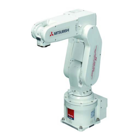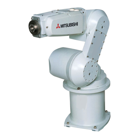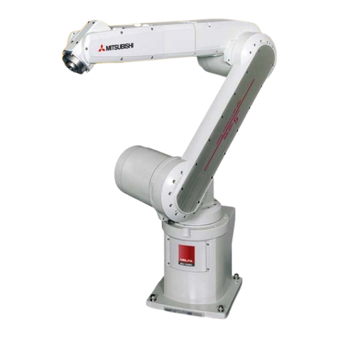
The points of the precautions given in the separate "Safety Manual" are given below.
Refer to the actual "Safety Manual" for details.
Use the robot within the environment given in the specifications. Failure to do so could
lead to a drop or reliability or faults.
(Temperature, humidity, atmosphere, noise environment, etc.)
Transport the robot with the designated transportation posture. Transporting the robot in
a non-designated posture could lead to personal injuries or faults from dropping.
Always use the robot installed on a secure table. Use in an instable posture could lead to
positional deviation and vibration.
Wire the cable as far away from noise sources as possible. If placed near a noise source,
positional deviation or malfunction could occur.
Do not apply excessive force on the connector or excessively bend the cable. Failure to
observe this could lead to contact defects or wire breakage.
Make sure that the work piece weight, including the hand, does not exceed the rated
load or tolerable torque. Exceeding these values could lead to alarms or faults.
Securely install the hand and tool, and securely grasp the work piece. Failure to observe
this could lead to personal injuries or damage if the object comes off or flies off during
operation.
Securely ground the robot and controller. Failure to observe this could lead to mal-
functioning by noise or to electric shock accidents.
Indicate the operation state during robot operation. Failure to indicate the state could
lead to operators approaching the robot or to incorrect operation.
When carrying out teaching work in the robot's movement range, always secure the
priority right for the robot control. Failure to observe this could lead to personal injuries or
damage if the robot is started with external commands.
Keep the jog speed as low as possible, and always watch the robot. Failure to do so
could lead to interference with the work piece or peripheral devices.
After editing the program, always confirm the operation with step operation before
starting automatic operation. Failure to do so could lead to interference with peripheral
devices because of programming mistakes, etc.
Make sure that if the safety fence entrance door is opened during automatic operation,
the door is locked or that the robot will automatically stop. Failure to do so could lead to
personal injuries.
Never carry out modifications based on personal judgments, or use non-designated
maintenance parts. Failure to observe this could lead to faults or failures.
When the robot arm has to be moved by hand from an external area, do not place hands
or fingers in the openings. Failure to observe this could lead to hands or fingers catching
depending on the posture.
Do not stop the robot or apply emergency stop by turning the robot controller's main
power OFF. If the robot controller main power is turned OFF during automatic operation,
the robot accuracy could be adversely affected. Moreover, it may interfere with the
peripheral device by drop or move by inertia of the arm.
Do not turn of the main power to the robot controller while rewriting the internal
information of the robot controller such as the program or parameters. If the main power
to the robot controller is turned off while in automatic operation or rewriting the program
or parameters, the internal information of the robot controller may be damaged.
CAUTION
CAUTION
CAUTION
WARNING
CAUTION
CAUTION
CAUTION
CAUTION
CAUTION
CAUTION
CAUTION
CAUTION
CAUTION
CAUTION
CAUTION
CAUTION
CAUTION

