manuals.online logo
Brands
  1. Home
  2. •
  3. Brands
  4. •
  5. Mitsubishi
  6. •
  7. Robotics
  8. •
  9. Mitsubishi SQ Series User manual

Mitsubishi SQ Series User manual

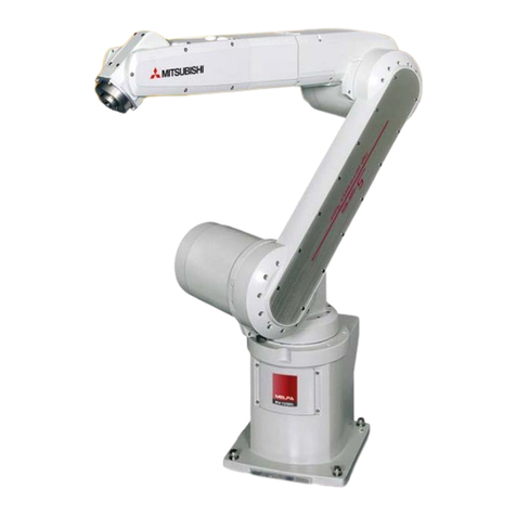
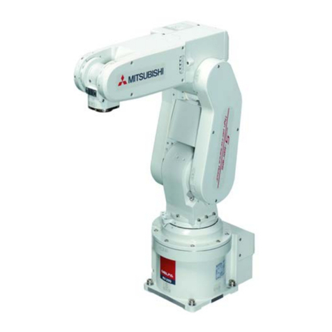
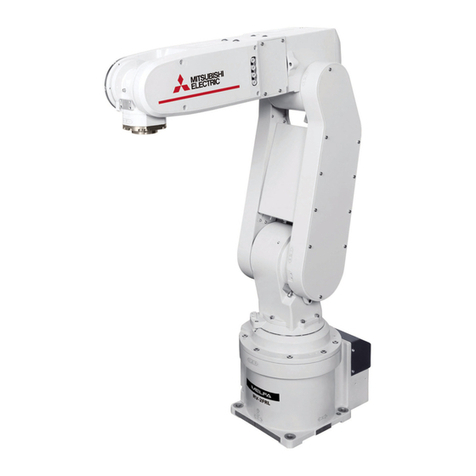
Mitsubishi Industrial Robot
SQ
Series
RV-12SQ/12SQ
L
Series
Special Specifications Manual
(CR2QA-701/CR3Q-701M/CR3Q-701 Controller)
BFP-A8692-R
All teaching work must be carried out by an operator who has received special
training. (This also applies to maintenance work with the power source turned
ON.)
En orcement o sa ety training
For teaching work, prepare a work plan related to the methods and procedures
o operating the robot, and to the measures to be taken when an error occurs
or when restarting. Carry out work ollowing this plan. (This also applies to
maintenance work with the power source turned ON.)
Preparation o work plan
Prepare a device that allows operation to be stopped immediately during
teaching work. (This also applies to maintenance work with the power source
turned ON.)
Setting o emergency stop switch
During teaching work, place a sign indicating that teaching work is in progress
on the start switch, etc. (This also applies to maintenance work with the power
source turned ON.)
Indication o teaching work in progress
Provide a ence or enclosure during operation to prevent contact o the
operator and robot.
Installation o sa ety ence
Establish a set signaling method to the related operators or starting work, and
ollow this method.
Signaling o operation start
As a principle turn the power OFF during maintenance work. Place a sign
indicating that maintenance work is in progress on the start switch, etc.
Indication o maintenance work in progress
Be ore starting work, inspect the robot, emergency stop switch and other
related devices, etc., and con irm that there are no errors.
Inspection be ore starting work
Always read the following precautions and the separate "Safety
Manual" before starting use of the robot to learn the required
measures to be taken.
Safety Precautions
CAUTION
CAUTION
WARNING
CAUTION
WARNING
CAUTION
CAUTION
CAUTION
The points o the precautions given in the separate "Sa ety Manual" are given below.
Re er to the actual "Sa ety Manual" or details.
Use the robot within the environment given in the speci ications. Failure to do
so could lead to a drop or reliability or aults. (Temperature, humidity,
atmosphere, noise environment, etc.)
Transport the robot with the designated transportation posture. Transporting
the robot in a non-designated posture could lead to personal injuries or aults
rom dropping.
Always use the robot installed on a secure table. Use in an instable posture
could lead to positional deviation and vibration.
Wire the cable as ar away rom noise sources as possible. I placed near a noise
source, positional deviation or mal unction could occur.
Do not apply excessive orce on the connector or excessively bend the cable.
Failure to observe this could lead to contact de ects or wire breakage.
Make sure that the workpiece weight, including the hand, does not exceed the
rated load or tolerable torque. Exceeding these values could lead to alarms or
aults.
Securely install the hand and tool, and securely grasp the workpiece. Failure to
observe this could lead to personal injuries or damage i the object comes o or
lies o during operation.
Securely ground the robot and controller. Failure to observe this could lead to
mal unctioning by noise or to electric shock accidents.
Indicate the operation state during robot operation. Failure to indicate the state
could lead to operators approaching the robot or to incorrect operation.
When carrying out teaching work in the robot's movement range, always secure
the priority right or the robot control. Failure to observe this could lead to
personal injuries or damage i the robot is started with external commands.
Keep the jog speed as low as possible, and always watch the robot. Failure to do
so could lead to inter erence with the workpiece or peripheral devices.
A ter editing the program, always con irm the operation with step operation
be ore starting automatic operation. Failure to do so could lead to inter erence
with peripheral devices because o programming mistakes, etc.
Make sure that i the sa ety ence entrance door is opened during automatic
operation, the door is locked or that the robot will automatically stop. Failure to
do so could lead to personal injuries.
Never carry out modi ications based on personal judgments, or use non-
designated maintenance parts.
Failure to observe this could lead to aults or ailures.
When the robot arm has to be moved by hand rom an external area, do not
place hands or ingers in the openings. Failure to observe this could lead to
hands or ingers catching depending on the posture.
CAUTION
CAUTION
CAUTION
CAUTION
CAUTION
CAUTION
WARNING
WARNING
CAUTION
WARNING
CAUTION
CAUTION
CAUTION
CAUTION
WARNING
Do not stop the robot or apply emergency stop by turning the robot controller's
main power OFF. I the robot controller main power is turned OFF during
automatic operation, the robot accuracy could be adversely a ected. Moreover,
it may inter ere with the peripheral device by drop or move by inertia o the arm.
Do not turn o the main power to the robot controller while rewriting the
internal in ormation o the robot controller such as the program or parameters.
I the main power to the robot controller is turned o while in automatic
operation or rewriting the program or parameters, the internal in ormation o the
robot controller may be damaged.
Use the network equipments (personal computer, USB hub, LAN hub, etc)
con irmed by manu acturer. The thing unsuitable or the FA environment
(related with con ormity, temperature or noise) exists in the equipments
connected to USB, RS-232 or LAN. When using network equipment, measures
against the noise, such as measures against EMI and the addition o the errite
core, may be necessary. Please ully con irm the operation by customer.
Guarantee and maintenance o the equipment on the market (usual o ice
automation equipment) cannot be per ormed.
CAUTION
CAUTION
CAUTION
■ Revision history
Date of print Specifications No. Details of revisions
2008-10-30 BFP-A8692 First print.
2009-6-23 BFP-A8692-A The English expression was orre ted.
Safety Pre autions , 1.1.2 Spe ial spe ifi ations , Table 1.3: The list of Option equipment
and spe ial spe ifi ation , Caution of USB devi es , 2.6.1 Shipping spe ial spe ifi ations ,
6.1.7 Examples of safety measures
Error in writing was orre ted.
2009-07-17 BFP-A8692-B Parameter AREA*CS was added.
2009-08-04 BFP-A8692-C CE Marking spe ifi ation was added.
2009-09-12 BFP-A8692-D The examples of safety measures ( Wiring example 3 ~ 5 ) were orre ted.
2009-10-26 BFP-A8692-E ・ The figure of key swit h in "3.6.3 Door swit h fun tion " was orre ted. (Error in writing)
・ The figure of example of safety measures in "6.1.7 Examples of safety measures " was
orre ted. ( onne ts the enabling swit h)
・ The EC De laration of Conformity was hanged.
(Correspond to the EMC dire tive; 2006/42/EC)
2009-12-04 BFP-A8692-F ・ Fuse ratisg of pneumati hand interfa e (RZ365/375) was orre ted.
・The text of "This interfa e is pre-installed on the ontroller" in pneumati hand interfa e
was deleted .
・Extended Function Instruction Manual was added.
2010-07-27 BFP-A8692-G ・ CR2QA-700 series ontroller onne tion spe ifi ation was added. (RV-12SQ-S300
Series)
・ CE spe ifi ation of the CR2QA-700 series ontroller was added. (RV-12SQ-S312
series)
・ Cover pa king was added to the onsumable part.
・ The des ription of prote tion spe ifi ation was hanged. (The utting oil whi h examined
was updated, and repla ement of the over pa king was added)
・ EC De laration of Conformity were added.
2010-10-13 BFP-A8692-H ・ The dimensions of the hole whi h draws the power able were added. (DU2A drive unit)
・ Power apa ity was orre ted.(old value: 3.0kVA)
・ The EC De laration of Conformity were added.
2010-11-30 BFP-A8692-J ・ The EC De laration of Conformity were added.
2010-12-21 BFP-A8692-K ・ The sink / sour e expression of pin assignment of hand input able was orre ted.
(Sink / Sour e are ommon)
2011-02-02 BFP-A8692-L ・ The note about temperature of the air to supply for hand was added.
・ Part ode was added to the onsumable part.
・ The type of ma hine able extension optional was orre ted.
(Error in writing: 1S- □□ CBL-02/1S- □□ LCBL-02)
2011-05-09 BFP-A8692-M ・ The 1N-ST0602C (One set: 2 p s.), 1N-ST0604C (Two set: 4 p s.), 1N-ST0606C (Three
set: 6 p s.) were added to Hand url tube optional.
・ Table 1-4: Re ommendation arti le of the USB able was orre ted.
・ The pressure of the dry air for pressurization was orre ted (error in writing).
・The depth in whi h the s rew of the me hani al interfa e se tion is tightened was added.
2011-06-01 BFP-A8692-N ・ The user's guide was added based on South Korean Radio Law.
・ Fuse rating of pneumati hand interfa e (RZ365/375) was orre ted. (error in writing).
・ The setting value range of parameter SFC*ME and AREA*ME were orre ted. (error in
writing).
2011-07-01 BFP-A8692-P ・ The note about the onne tion of the emergen y stop was added.
2012-01-26 BFP-A8692-Q ・ The EC De laration of Conformity were hanged.
2012-07-11 BFP-A8692-R ・ The "Emergen y stop output" in the ontroller standard spe ifi ation table was deleted.
(Overlapped with "Robot error output".)
・The "Table 3-3 : Emergen y stop/Door swit h input" in "3.4 External input/output" was
deleted. (Overlapped with "Table 3-5 : Spe ial input/output terminal".)
・ The Effe tive se tional area of the solenoid valve (optional) was orre ted. (Error in
writing)
・ The EC De laration of Conformity were hanged.
・ The notes about frequent installation and removal of TB and the dummy onne tor were
added.
・ The note about the onne tion of the emergen y stop was added.
・ The explanation about the ontroller of KC mark spe ifi ation was added to " ■
Introdu tion".
Date of print Specifications No. Details of revisions
■ Introduction
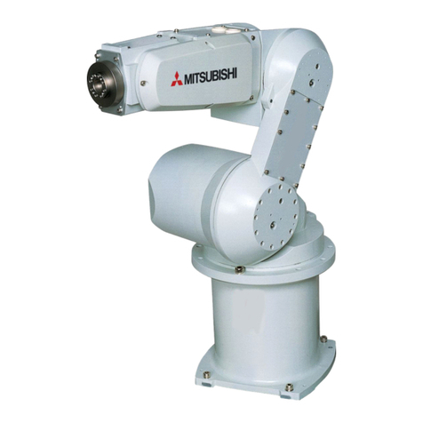
This series is a ull-scale industrial vertical multi-joint type robot that is designed or use in machining
processes and assembling. This series supports the oil mist environment as standard, o ering a variety o
speci ications including clean speci ication and long-arm speci ication.
However, to comply with the target application, a work system having a well-balanced robot arm, periph-
eral devices or robot and hand section must be structured.
When creating these standard speci ications, we have edited them so that the Mitsubishi robot's charac-
teristics and speci ications can be easily understood by users considering the implementation o robots.
However, i there are any unclear points, please contact your nearest Mitsubishi branch or dealer.
Mitsubishi hopes that you will consider these standard speci ications and use our robots.
Note that in this speci ication document the speci ications related to the robot arm is described Page 7,
"2 Robot arm", the speci ications related to the controller Page 38, "3 Controller", and so tware unc-
tions and a command list Page 88, "4 So tware" separately.
This document has indicated the speci ication o the ollowing types robot.
*RV-12SQ
*RV-12SQC
*RV-12SQL
*RV-12SQLC
About KC mark specifications
This robot acquires certi ication o KC mark by the special speci ication (S19).
The external orm o drive unit which have KC mark speci ication is same as the drive unit which
described as "CE Marking speci ication".
Re er to the place described as "CE Marking speci ication" about the external orm o KC mark
speci ication's drive unit.
Especially the places with no distinction are common speci ications.
・ No part o this manual may be reproduced by any means or in any orm, without prior consent rom
Mitsubishi.
・ The contents o this manual are subject to change without notice.
・ The speci ications values are based on Mitsubishi standard testing methods.
・ The in ormation contained in this document has been written to be accurate as much as possible.
Please interpret that items not described in this document "cannot be per ormed." or "alarm
may occur".
Please contact your nearest dealer i you ind any doubt ul, wrong or skipped point.
・ This speci ications is original.
・ Microso t, Windows, Microso t Windows NT are either registered trademarks or trademarks o
Microso t Corporation in the United States and/or other countries.
Copyright(C) 2008-2012 MITSUBISHI ELECTRIC CORPORATION
Contents
i
Page
1 General con iguration .................................................................................................................................................................... 1-1
1.1 Structural equipment ............................................................................................................................................................. 1-1
1.1.1 Standard structural equipment .................................................................................................................................. 1-1
1.1.2 Special speci ications .................................................................................................................................................... 1-1
1.1.3 Options ................................................................................................................................................................................. 1-1
1.1.4 Maintenance parts ........................................................................................................................................................... 1-1
1.2 Model type name o robot .................................................................................................................................................... 1-2
1.2.1 How to identi y the robot model ................................................................................................................................ 1-2
1.2.2 Combination o the robot arm and the controller .............................................................................................. 1-2
1.3 CE marking speci ications .................................................................................................................................................... 1-2
1.4 Indirect export .......................................................................................................................................................................... 1-2
1.5 Instruction manuals ................................................................................................................................................................ 1-2
1.6 Contents o the structural equipment ............................................................................................................................ 1-3
1.6.1 Robot arm ........................................................................................................................................................................... 1-3
1.6.2 Controller ............................................................................................................................................................................ 1-4
1.7 Contents o the Option equipment and special speci ication .............................................................................. 1-5
2 Robot arm ........................................................................................................................................................................................... 2-7
2.1 Standard speci ications ........................................................................................................................................................ 2-7
2.1.1 The counter- orce applied to the installation sur ace ..................................................................................... 2-8
2.2 De inition o speci ications .................................................................................................................................................. 2-9
2.2.1 Pose repeatability ............................................................................................................................................................ 2-9
2.2.2 Rated load (mass capacity) ....................................................................................................................................... 2-10
2.2.3 Relationships Among Mass Capacity, Speed, and Acceleration/Deceleration Speed ...................... 2-11
(1) Setting Load Capacity and Size (Hand Conditions) .................................................................................... 2-11
2.2.4 Vibrations at the Tip o the Arm during Low-Speed Operation o the Robot ..................................... 2-11
2.2.5 Protection speci ications ............................................................................................................................................ 2-12
(1) Types o protection speci ications .................................................................................................................... 2-12
(2) About the use with the bad environment ........................................................................................................ 2-12
2.2.6 Clean speci ications ...................................................................................................................................................... 2-14
(1) Types o clean speci ications ............................................................................................................................... 2-14
2.3 Names o each part o the robot .................................................................................................................................... 2-15
2.4 Outside dimensions ・ Operating range diagram ........................................................................................................ 2-16
(1) RV-12SQ/12SQC ..................................................................................................................................................... 2-16
(2) RV-12SQL/12SQLC ................................................................................................................................................ 2-18
2.5 Tooling ........................................................................................................................................................................................ 2-20
2.5.1 Wiring and piping or hand .......................................................................................................................................... 2-20
2.5.2 Internal air piping ............................................................................................................................................................ 2-21
2.5.3 Internal wiring or the pneumatic hand output cable ...................................................................................... 2-21
2.5.4 Internal wiring or the hand check input cable (Standard type/Clean type) ........................................ 2-21
2.5.5 Spare Wiring ..................................................................................................................................................................... 2-21
(1) Standard type ............................................................................................................................................................. 2-21
2.5.6 Wiring and piping system diagram or hand ......................................................................................................... 2-22
2.5.7 Electrical speci ications o hand input/output .................................................................................................. 2-24
2.5.8 Air supply circuit example or the hand ............................................................................................................... 2-25
2.6 Options ....................................................................................................................................................................................... 2-26
(1) Machine cable extension ........................................................................................................................................ 2-27
(2) Changing the operating range .............................................................................................................................. 2-30
(3) Solenoid valve set ..................................................................................................................................................... 2-31
(4) Hand input cable ........................................................................................................................................................ 2-33
(5) Hand output cable ..................................................................................................................................................... 2-34
(6) Hand curl tube ............................................................................................................................................................ 2-35
2.7 About Overhaul ...................................................................................................................................................................... 2-36
2.8 Maintenance parts ................................................................................................................................................................. 2-36
3 Controller .......................................................................................................................................................................................... 3-38
Contents
ii
Page
3.1 Standard speci ications ...................................................................................................................................................... 3-38
3.1.1 Standard speci ications ............................................................................................................................................... 3-38
3.1.2 Protection speci ications and operating supply ................................................................................................ 3-40
3.2 Names o each part .............................................................................................................................................................. 3-41
3.2.1 Names o each part o the drive unit .................................................................................................................... 3-41
(1) Padlock speci ication ............................................................................................................................................... 3-43
3.2.2 Names o each part o the robot CPU ................................................................................................................. 3-47
3.3 Outside dimensions/Installation dimensions .............................................................................................................. 3-48
3.3.1 Outside dimensions ....................................................................................................................................................... 3-48
(1) Drive unit outside dimension ................................................................................................................................ 3-48
(2) Outside dimensions o robot CPU unit ............................................................................................................ 3-52
(3) Battery unit outside dimension ........................................................................................................................... 3-53
3.3.2 Installation dimensions ................................................................................................................................................. 3-54
(1) Installation dimensions o drive unit .................................................................................................................. 3-54
(2) Robot CPU Unit installation dimensions .......................................................................................................... 3-56
3.3.3 Cable lead-in and dimension ..................................................................................................................................... 3-57
3.4 External input/output .......................................................................................................................................................... 3-59
3.4.1 Types .................................................................................................................................................................................. 3-59
3.5 Dedicated input/output ...................................................................................................................................................... 3-60
3.6 Emergency stop input and output etc. ......................................................................................................................... 3-62
3.6.1 Connection o the external emergency stop ...................................................................................................... 3-62
3.6.2 Special stop input(SKIP) ............................................................................................................................................. 3-65
3.6.3 Door switch unction .................................................................................................................................................... 3-67
3.6.4 Enabling device unction ............................................................................................................................................. 3-67
(1) When door is opening ............................................................................................................................................... 3-67
(2) When door is closing ................................................................................................................................................ 3-67
(3) Automatic Operation/Jog Operation/Brake Release and Necessary Switch Settings .............. 3-68
3.7 Additional Axis Function ..................................................................................................................................................... 3-69
3.7.1 Wiring o the Additional Axis Inter ace ................................................................................................................. 3-69
3.8 Magnet contactor control connector output (AXMC) or addition axes ........................................................ 3-74
3.9 Options ....................................................................................................................................................................................... 3-77
(1) Teaching pendant (T/B) ......................................................................................................................................... 3-78
(2) Pneumatic hand inter ace ...................................................................................................................................... 3-81
(3) RT ToolBox2/RT ToolBox2 mini ......................................................................................................................... 3-84
(4) Instruction Manual(bound edition) ...................................................................................................................... 3-86
3.10 Maintenance parts .............................................................................................................................................................. 3-87
4 So tware ............................................................................................................................................................................................ 4-88
4.1 List o commands .................................................................................................................................................................. 4-88
4.2 List o parameters ................................................................................................................................................................. 4-91
5 Instruction Manual ........................................................................................................................................................................ 5-93
5.1 The details o each instruction manuals ...................................................................................................................... 5-93
6 Sa ety ................................................................................................................................................................................................. 6-95
6.1 Sa ety ......................................................................................................................................................................................... 6-95
6.1.1 Sel -diagnosis stop unctions ................................................................................................................................... 6-95
6.1.2 External input/output signals that can be used or sa ety protection measures .............................. 6-96
6.1.3 Precautions or using robot ....................................................................................................................................... 6-96
6.1.4 Sa ety measures or automatic operation ........................................................................................................... 6-97
6.1.5 Sa ety measures or teaching .................................................................................................................................. 6-97
6.1.6 Sa ety measures or maintenance and inspections, etc. .............................................................................. 6-97
6.1.7 Examples o sa ety measures ................................................................................................................................... 6-98
(1) External emergency stop connection [supplementary explanation] ................................................. 6-102
6.2 Working environment ......................................................................................................................................................... 6-103
6.3 Precautions or handling .................................................................................................................................................. 6-103
Contents
iii
Page
7Appendix ........................................................................................................................................................................... Appendix-105
Appendix 1 : Speci ications discussion material ........................................................................................ Appendix-105
1-1 Structural equipment
1General configuration
1 General configuration
1.1 Structural equipment
Structural equipment consists o the ollowing types.
. . Standard structural equipment
The ollowing items are enclosed as a standard.
(1) Robot arm
(2) Controller(CPU unit + Drive unit)
(3) The connecting cable or the CPU unit and the drive unit
(4) Machine cable
(5) Robot arm installation bolts
(6) Sa ety manual, Instruction manual, CD-ROM (Instruction manual)
(7) Guarantee card
. .2 Special specifications
For the special speci ications, some standard con iguration equipments and speci ications have to be changed
be ore actory shipping. Con irm the delivery date and speci y the special speci ications at the order.
. .3 Options
User can install options a ter their delivery.
. .4 Maintenance parts
Materials and parts or the maintenance use.
1General configuration
Model type name of robot 1-2
1.2 Model type name of robot
.2. How to identify the robot model
RV-12SQ L C -Sxx
( a ) ( b ) ( c ) ( d )
(a). RV-12SQ................................. Indicates the RV-12SQ series.
(b). L.................................................. Indicates long arm type.
Examples)
Blank: Standard type.
L: Long arm type.
(c). C ................................................. Indicates environment speci ication.
Examples)
Blank: Standard Speci ications
C: Clean Speci ications
(d). -Sxx........................................... [1] Indicates a special model number. In order, limit special speci ica-
tion.
.2.2 Combination of the robot arm and the controller
Table 1-1 : Combination o the robot arm and the controller
1.3 CE marking pecification
The RV-12SQ series provides models with CE marking speci ications as well.
Table 1-2 : Robot models with CE marking speci ications
1.4 Indirect export
The display in English is available by setting parameter LNG as "ENG."
1.5 In truction manual
The instruction manuals supplied in CD-ROM, except or the Sa ety Manual. This CD-ROM (electronic manual)
includes instruction manuals in both Japanese and English versions.
Protection specification Robot arm Controller
Standard specification R -12SQstandard arm CR3Q-701MNote1)
Note1) DU3-701M is protection speci ication. (IP54) Especially, strengthened the protection per ormance to oil
mist.
R -12SQLLong arm
R -12SQ-S300 standard arm CR2QA-701-S300Note2)
Note2) CR2QA-701 is a general environment speci ication. Please choose CR3D-701M, when the controller is
used in the oil mist environment etc.
R -12SQL-S300 Long arm
Clean specification R -12SQCstandard arm CR3Q-701Note3)
Note3) DU3-701 is protection speci ication. (IP54)
R -12SQLC Long arm
R -12SQC-S300 standard arm CR2QA-701-S300Note4)
Note4) CR2QA-701 is a general environment speci ication. I the controller used in the clean environment, install
to the place which does not have e ect to cleanness.
R -12SQLC-S300 Long arm
Robot type ControllerNote1)
Note1) DU3-701M/DU3-701 is protection speci ication. (IP54) Especially, the CR3Q-701M (DU3-701M
drive unit) has strengthened the protection per ormance to oil mist.
External signal logi Language setting
RV-12SQ-S12/12SQL-S12
RV-12SQC-S12/12SQLC-S12
RV-12SQ-S312/12SQL-S312
RV-12SQC-S312/12SQLC-S312
CR3Q-701M/
CR3Q-701
CR2QA-701-S312
CR2QA-701-S312
Sour e type English (ENG)
1-3 Contents of the structural equipment
1General configuration
1.6 Content of the tructural equipment
.6. Robot arm
The list o structural equipment is shown in Fig. 1-1.
Fig.1-1 : Structural equipment (Robot arm)
Vertical six-axis
multiple-jointed type
(RV-12SQ/12SQL/12SQC/12SQLC)
Hand output cable
・ 1S-GR35S-01 (4sets)
Hand input cable
・ 1S-HC25C-01
Solenoid valve set
(Special hand output cable is attached)
<Sink type/Source type>
・ 1 set: 1S- D01-01/1S- D01E-01
・ 2 set: 1S- D02-01/1S- D02E-01
・ 3 set: 1S- D03-01/1S- D03E-01
・ 4 set: 1S- D04-01/1S- D04E-01
Hand curl tube
・ 4 set, 8pc.: 1N-ST0608C
Stopper or changing the operating range
o the J1 axis
・ Stopper part: 1S-DH-01
*Installed by customer.
[Caution] Standard con iguration
Special speci ications
Option
equipment
Prepared by customer
Pneumatic hand customer-manufactured parts
Note1) □□ refer the length.
Refer to Table 1-3 for details.
Note2) Connect the extension cables to
the arm side of the standard 7 m
(for fixing) cable to extend.
Machine cable extension
(attached to the standard 7 m cable)
・ Fix type: 1S- □□ CBL-01
・Flex type: 1S-□□LCBL-01
Machine cable
(Standard product: 7m attachment)
1 General configuration
1-4
.6.2 Controller
The devices shown below can be installed on the controller.
The controllers that can be connected di er depending on the speci ication o the robot.
Fig.1-2 : Structural equipment
Instruction Manual
(printed)
・ 5S-QC00-PE01
*4) The previous R28TB an be used if the relay onne tor box is used.
And, sin e the R28TB operation method is the same as before, refer
to the instru tions manual whi h on hand.
Standard con iguration
Special speci ications
Options
Prepared by
[Caution]equipment
customer
*5) Corresponding to the sink or sour e to be
used, setting of the drive unit is ne essary.
Controller ・ CR2QA-701, CR3Q-701M/701
Cable
・ 2Q-TUCBL 10M (TU Cable for robot)
・ 2Q-DISPCBL10M (DISP Cable for robot )
・ 2Q-EMICBL 10M (EMI Cable for robot)
・ MR-J3BUS10M-A10M (SSCNET Ⅲ Cable for robot)
Caster type
Drive unit DU3-701*-S01
*1)The base board, the power supply unit, and sequen er CPU are required
for installation of the robot CPU unit.
Prepared by ustomer
*2) The ontroller of "-S300" spe ifi ation is CR2QA-701.
*3) The ontroller of CE Marking spe ifi ation
"-S12" spe ifi ation: the ontroller is CR3Q-700 series.
"-S312" spe ifi ation: the ontroller is CR2QA-700 series.
Drive unit
・ DU2A-700 series
*3)*2)
Drive unit
・ DU3-701M/701
*3)
Robot CPU unit
・ Q172DRCPU *1)
Pneumatic hand inter ace
2A-RZ365(Sink)/
2A-RZ375(Sour e)
*5)
Teaching pendant (T/B) ・ R32TB/R56TB *4)
<R32TB> <R56TB>
Personal computer
Prepared by customer
Personal computer cable
Prepared by
customer
RS-232,USB,
Ethernet
*)Refer toTable
1-4 for USB
able.
RT Tool Box2
(MS-Windows2000/XP/ ista)
・ 3D-11C-WINJ(CD-ROM)
RT Tool Box2 mini
(MS-Windows2000/XP/ ista)
・ 3D-12C-WINJ(CD-ROM)
1-5 Contents of the Option equipment and special specification
1 General configuration
1.7 Content of the Option equipment and pecial pecification
A list o all Optional equipments and special speci ications are shown below.
Table 1-3 : The list o Option equipment and special speci ication
[Re erence]:The recommendation products o the USB cable are shown below.
Table 1-4 : Recommendation article o the USB cable
Item Type Specifications Classification
Note1)
Note1) ○ : option, □ : special speci ications.
Description
Stopper for hanging the
operating range of the J1
axis
1S-DH-01 Stopper part
One ea h of the following an be
sele ted.
+ side: +135, +90, or +45 deg.
- side: -135, -90, or -45 deg.
±170 deg. are used for the standard
spe ifi ation.
○
This must be installed by the ustomer.
Extended ma hine able 1S- □□ CBL-01 For fixing (Set of power, signal and
ground) ○ 5, 10, 15m
1S- □□ LCBL-01 For bending (Set of power, signal and
ground) ○ 5, 10, 15m
Solenoid valve set 1S-VD01-01/
1S-VD01E-01 1 set (Sink type)/(Sour e type) ○
A solenoid valve set for the pneumati hand
1S-VD02-01/
1S-VD02E-01 2 set (Sink type)/(Sour e type) ○
1S-VD03-01/
1S-VD03E-01 3 set (Sink type)/(Sour e type) ○
1S-VD04-01/
1S-VD04E-01 4 set (Sink type)/(Sour e type) ○
Hand output able 1S-GR35S-01 Robot side: onne tor.
Hand side: wire. ○The able is onne ted to the hand output
onne tor by the ustomer.
Hand input able 1S-HC25C-01 Robot side: onne tor.
Hand side: wire. ○The able is onne ted to the sensor by the
ustomer.
Hand url tube 1N-ST0602C For solenoid valve 1set.:Φ6x2 ○
Curl type air tube
1N-ST0604C For solenoid valve 2set.:Φ6x4 ○
1N-ST0606C For solenoid valve 3set.:Φ6x6 ○
1N-ST0608C For solenoid valve 4set.:Φ6x8 ○
Simple tea hing pendant R32TB Cable length 7m ○
With 3-position deadman swit h IP65
R32TB-15 Cable length 15m ○
Highly effi ient tea hing
pendant
R56TB Cable length 7m ○
R56TB-15 Cable length 15m ○
Pneumati hand interfa e 2A-RZ365 DO: 8 point(Sink type)○ It is ne essary when the hand output signal of
the robot arm is used.
2A-RZ375 DO: 8 point(Source type)○
Caster spe ifi ations
ontroller CR3Q-700M Spe ifi ations with asters □ The ontroller height
will be h =615
RT ToolBox2
(Personal omputer Sup-
port software) 3D-11C-WINE CD-ROM ○ MS-Windows2000/XP Vista
(With the simulation fun tion)
RT ToolBox2 mini
(Personal omputer Sup-
port software mini) 3D-12C-WINE CD-ROM ○ MS-Windows2000/XP Vista
TU able for robot 2Q-TUCBL □ M Cable length 05、 10、 20、 30m ○ For communication between robot CPU and DU.
DISP able for robot 2Q-DISPCBL □ M Cable length 05、 10、 20、 30m ○ For communication between robot CPU and DU.
EMI able for robot 2Q-EMICBL □ M Cable length 05、 10、 20、 30m ○ For a robot CPU emergency stop input.
SSCNET Ⅲ able for robot MR-J3BUS □ M-A Cable length 05、 10、 20m ○ For the servo communication between robot CPU
and DU .
MR-J3BUS30M-B Cable length 30m ○
Instruction Manual 5S-QC00-PE01 RV-12SQ 12SQL series ○A set of the instructions manual bookbinding
editions
Name Type name Supplier
USB cable
(USB A type-USB mini B type)
KU-AMB530 SANWA SUPPLY INC.
USB-M53 ELECOM CO., LTD.
GT09-C30USB-5P MITSUBISHI ELECTRIC SYSTEM & SERVICE CO., LTD.
MR-J3USBCBL3M MITSUBISHI ELECTRIC CO., LTD.
USB adapter
(USB B type-USB mini B type) AD-USBBFTM5M ELECOM CO., LTD.
1 General configuration
Contents of the Option equipment and special specification 1-6
Be care ul to the USB cable to apply neither the static electricity nor the noise.
Otherwise, it becomes the cause o mal unction.
Use the network equipments (personal computer, USB hub, LAN hub, etc) con irmed by
manu acturer. The thing unsuitable or the FA environment (related with con ormity,
temperature or noise) exists in the equipments connected to USB, RS-232 or LAN. When
using network equipment, measures against the noise, such as measures against EMI and
the addition o the errite core, may be necessary. Please ully con irm the operation by
customer. Guarantee and maintenance o the equipment on the market (usual o ice
automation equipment) cannot be per ormed.
Caution
Caution
2-7 Standard specifications
2Robot arm
2 Robot arm
2.1 Standard pecification
Table 2-1 : Standard speci ications o robot
Item Unit Specifications
Type RV-12SQ RV-12SQC RV-12SQL RV-12SQLC
Type of robot
6-axis standard arm 6-axis long arm
Standard Clean
(Spe ial Spe ifi ations) Standard Clean
(Spe ial Spe ifi ations)
Degree of freedom 6
Installation posture On floor, hanging
(against wall Note1) )
Note1) When used by mounting on the wall a special specification that limits the operating range of the J1 axis will be used. Please
give an order separately.
On floor On floor, hanging
(against wall Note1))
On floor
Stru ture Verti al, multiple-joint type
Drive system AC servo motor (brake provided on all axes)
Position dete tion method Absolute en oder
Arm length
Shoulder shift
mm
150 150
Upper arm 400 560
Fore arm 530 670
Elbow shift 80 80
Wrist length 97 97
Operating
range
Waist (J1)
Degree
340(-170 to +170)
Shoulder (J2) 230(-100 to +130)
Elbow (J3) 290(-130 to +160)
Wrist twist (J4) 320(-160 to +160)
Wrist pit h (J5) 240(-120 to +120)
Wrist roll (J6) 720(-360 to +360)
Speed of
motion
Waist (J1)
Degree/
s
276 230
Shoulder (J2) 230 172
Elbow (J3) 267 200
Wrist twist (J4) 352
Wrist pit h (J5) 375
Wrist roll (J6) 660
Maximum resultant velo ity Note2)
Note2) This is the value on the mechanical interface surface when all axes are combined.
mm/se Approx. 9,600 Approx. 9,500
Load Maximum Note3)
Note3) The maximum load capacity is the mass with the mechanical interface posture facing down word at the ±10°limit.
kg
(N)
12 (117.6)
Rating 10 (98.0)
Pose repeatability Note4)
Note4) The pose repeatability details are given in Page 9 "2.2.1 Pose repeatability"
mm ±0.05
Ambient temperature ℃ 0 to 40
mass kg Approx. 93 Approx. 98
Allowable
moment load
Wrist twist (J4)
N・m
19.3
Wrist pit h (J5) 19.3
Wrist roll (J6) 11
Allowable
inertia
Wrist twist (J4)
kg ・ m2
0.4
Wrist pit h (J5) 0.4
Wrist roll (J6) 0.14 Note5)
Note5) Up to 0.28kg ・ m2 can be supported by performing variable acceleration/deceleration control and also by setting the load iner-
tia.
Arm rea hable radius front p-axis
enter point mm 1,086 1,385
Tool wiring Note6)
Note6) The pneumatic hand interface (option) is required when the tool (hand) output is used. Also if the solenoid set (option) is
used eight points of hand outputs are used for other options. 。
Hand input 8 point / hand output 8 point
Eight spare wires : AWG#27(0.1mm2)
(shielded)
Tool pneumati pipes Primary side: Φ6×2 , Se ondary side: Φ6× 8
Supply pressure MPa 0.49±10%
Prote tion spe ifi ationNote7)
Note7) The protection specification details are given in Page 12 "2.2.5 Protection specifications".
J1 to J3 axis : IP54
J4 to J6 axis : IP65 -J1 to J3 axis : IP54
J4 to J6 axis : IP65 -
Degree of leanlinessNote8)
Note8) The clean specification details are given in Page 14 "2.2.6 Clean specifications" .A down flow(0.3m/s or more) in the clean
room is the necessary conditions for the cleanliness.
-
10(0.3μm)
Internal su tion
requirement
-
10(0.3μm)
Internal su tion
requirement
Painting olor Light gray (Equivalent to Munsell: 0.08GY7.64/0.81)
2Robot arm
Standard specifications 2-8
2.1.1 The counter- orce applied to the installation sur ace
The counter- orce applied to the installation sur ace or the strength design o the robot installation sur ace is
shown.
Table 2-2 : Value o each counter- orce
Item Unit Value
Falls moment: MLN•m 1, 530
Torsion moment: MTN•m 1, 530
Horizontal translation force: FHN 1, 300
ertical translation force: FVN 2, 300
2-9 Definition of specifications
2 Robot arm
2.2 Definition of pecification
The accuracy o pose repeatability mentioned in catalogs and in the speci ication manual is de ined as ollows.
2.2. Pose repeatability
For this robot, the pose repeatability is given in accordance with JIS 8432 (Pose repeatability). Note that the value
is based on 100 measurements (although 30 measurements are required according to JIS).
[Caution] The speci ied "pose repeatability" is not guaranteed to be satis ied under the ollowing conditions.
[1] Operation pattern actors
1) When an operation that approaches rom di erent directions and orientations are included in rela-
tion to the teaching position during repeated operations
2) When the speed at teaching and the speed at execution are di erent
[2] Load luctuation actor
1) When work is present/absent in repeated operations
[3] Disturbance actor during operation
1) Even i approaching rom the same direction and orientation to the teaching position, when the
power is turned OFF or a stop operation is per ormed hal way
[4] Temperature actors
1) When the operating environment temperature changes
2) When accuracy is required be ore and a ter a warm-up operation
[5] Factors due to di erences in accuracy de inition
1) When accuracy is required between a position set by a numeric value in the robot's internal coor-
dinate system and a position within the actual space
2) When accuracy is required between a position generated by the pallet unction *1) and a position
within the actual space
*1)
The pallet unction is a unction that teaches only the position o the work used as re erence (3 to 4 points) and
obtains the remaining positions by calculations, or an operation that arranges works orderly or or an operation
that unloads orderly arranged works. By using this unction, or example, in the case o an operation that arranges
works on grid points o 100 x 100, by teaching only three points o our corners, the remaining grid points are
automatically generated; thus, it is not necessary to teach all 10,000 points. For more in ormation about the pallet
unction, re er to the separate volume, "Instruction Manual/Detailed Explanation o Functions and Operations."

This manual suits for next models

5

Other Mitsubishi Robotics manuals

Mitsubishi RV-2F Series User manual

Mitsubishi

Mitsubishi RV-2F Series User manual

Mitsubishi RH-3SQHR3515 User manual

Mitsubishi

Mitsubishi RH-3SQHR3515 User manual

Mitsubishi CR750-Q Series User manual

Mitsubishi

Mitsubishi CR750-Q Series User manual

Mitsubishi MELFA RH-3FH-D Series User manual

Mitsubishi

Mitsubishi MELFA RH-3FH-D Series User manual

Mitsubishi MELFA RV-6S Series User manual

Mitsubishi

Mitsubishi MELFA RV-6S Series User manual

Mitsubishi MELFA RV-6S Series User manual

Mitsubishi

Mitsubishi MELFA RV-6S Series User manual

Mitsubishi RP-1AH Series User manual

Mitsubishi

Mitsubishi RP-1AH Series User manual

Mitsubishi MELFA SQ Series User manual

Mitsubishi

Mitsubishi MELFA SQ Series User manual

Mitsubishi RV-3SJ Series User manual

Mitsubishi

Mitsubishi RV-3SJ Series User manual

Mitsubishi RV-2AJ Use and care manual

Mitsubishi

Mitsubishi RV-2AJ Use and care manual

Mitsubishi RV-12SD Series User manual

Mitsubishi

Mitsubishi RV-12SD Series User manual

Mitsubishi RV-2AJ User manual

Mitsubishi

Mitsubishi RV-2AJ User manual

Mitsubishi MELFA RH-6SH Series User manual

Mitsubishi

Mitsubishi MELFA RH-6SH Series User manual

Mitsubishi MELFA RH-3SDHR3515 User manual

Mitsubishi

Mitsubishi MELFA RH-3SDHR3515 User manual

Mitsubishi RV-12SD Series User manual

Mitsubishi

Mitsubishi RV-12SD Series User manual

Mitsubishi RV-2F-D Series User manual

Mitsubishi

Mitsubishi RV-2F-D Series User manual

Mitsubishi R56TB User manual

Mitsubishi

Mitsubishi R56TB User manual

Mitsubishi MELFA SD Series User manual

Mitsubishi

Mitsubishi MELFA SD Series User manual

Mitsubishi CRn-500 Series User manual

Mitsubishi

Mitsubishi CRn-500 Series User manual

Mitsubishi CRn-500 Series User manual

Mitsubishi

Mitsubishi CRn-500 Series User manual

Mitsubishi RH-3FH Series User manual

Mitsubishi

Mitsubishi RH-3FH Series User manual

Popular Robotics manuals by other brands

YASKAWA MOTOMAN-MH600 instructions

YASKAWA

YASKAWA MOTOMAN-MH600 instructions

Artec Robo 2.0 instructions

Artec

Artec Robo 2.0 instructions

Arexx Solar Cosmonaut quick start guide

Arexx

Arexx Solar Cosmonaut quick start guide

ADEEPT RaspClaws user manual

ADEEPT

ADEEPT RaspClaws user manual

Dobot CR16 Hardware user's guide

Dobot

Dobot CR16 Hardware user's guide

JAKA MiniCobo V1 user manual

JAKA

JAKA MiniCobo V1 user manual

Terasic SPIDER ROBOT user manual

Terasic

Terasic SPIDER ROBOT user manual

Robopac ROBOT MASTER Use and maintenance manual

Robopac

Robopac ROBOT MASTER Use and maintenance manual

ROKAE xMate CR12 Hardware installation manual

ROKAE

ROKAE xMate CR12 Hardware installation manual

Tregaskiss TOUGH GUN I.C.E. Technical Guide Addendum

Tregaskiss

Tregaskiss TOUGH GUN I.C.E. Technical Guide Addendum

Octopus T-MOOV manual

Octopus

Octopus T-MOOV manual

Epson G3 Series manual

Epson

Epson G3 Series manual

Boston Acoustics SPOT 2.0.1 manual

Boston Acoustics

Boston Acoustics SPOT 2.0.1 manual

MIR 250 Hook user guide

MIR

MIR 250 Hook user guide

VertiDrive M7 user manual

VertiDrive

VertiDrive M7 user manual

Robotical Marty the Robot Build guide

Robotical

Robotical Marty the Robot Build guide

LEGO STAR WARS 75145 manual

LEGO

LEGO STAR WARS 75145 manual

SoftBank Whiz manual

SoftBank

SoftBank Whiz manual

manuals.online logo
manuals.online logoBrands
  • About & Mission
  • Contact us
  • Privacy Policy
  • Terms and Conditions

Copyright 2025 Manuals.Online. All Rights Reserved.