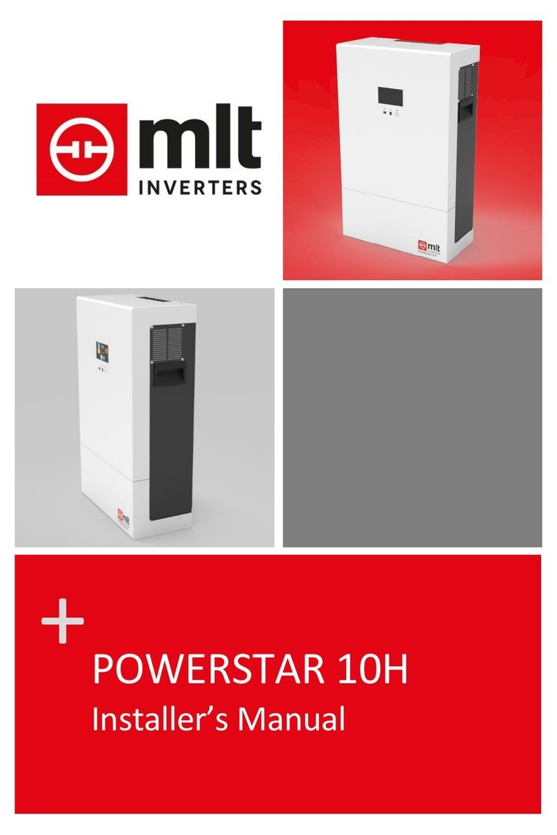
MLT Inverters Oasis 6036 User manual

OASIS-UM-01
MAY2012 ISSUE 01
UserManual
Inverter/Charger –Oasis 6000 Rev 1.0
Oasis 6000 Series

OASIS-UM-01
PAGE 2 MAY2012ISSUE01

OASIS-UM-01
MAY 2012 ISSUE01 PAGE 3
Oasis 6000 Series User Manual
Contents
1. Introduction.............................................................................................................6
1.1 Warnings and Cautions..................................................................................6
1.2 Contacting MLT Drives...................................................................................7
1.2.1 Product Support......................................................................................7
1.2.2 Contact Details........................................................................................7
1.2.3 Telephone...............................................................................................7
1.3 System Configuration.....................................................................................8
1.4 Specifications..................................................................................................9
1.4.1 AC Output specifications........................................................................9
1.4.2 AC Input specifications...........................................................................9
1.4.3 DC specifications....................................................................................9
1.4.4 General technical specifications...........................................................10
1.4.5 Climatic conditions................................................................................11
1.5 System Description.......................................................................................12
2. Setup and Operation............................................................................................15
2.1 Installing the Oasis 6000..............................................................................15
2.1.1 Selecting a suitable location.................................................................15
2.1.2 Mounting................................................................................................15
2.1.3 Making the electrical connections........................................................17
2.1.4 Setting up the Oasis 6000....................................................................19
2.1.5 Powering up the Oasis6000................................................................19
2.1.6 Powering down the Oasis 6000...........................................................19
2.2 Operation of the Oasis 6000........................................................................21
2.2.1 The user interface.................................................................................21
2.2.2 Operational Modes ...............................................................................22

OASIS-UM-01
PAGE 4 MAY2012ISSUE01
2.2.3 Status indicators....................................................................................22
2.3 Connecting an external AC source..............................................................24
2.3.1 Preparation............................................................................................24
2.3.2 Installing a Generator............................................................................24
3. About Batteries.....................................................................................................25
3.1 General.........................................................................................................25
3.2 Battery Bank Location..................................................................................25
3.3 Maintenance.................................................................................................26
3.4 Replacing a Battery......................................................................................26
3.5 Battery charger settings................................................................................26
3.5.1 Selecting the battery charging current .................................................27
3.5.2 Selecting the battery charging voltage.................................................27
4. About Solar Panels..............................................................................................28
4.1 Introduction...................................................................................................28
4.2 Using a Solar System with the Oasis 6000.................................................28
5. Trouble Shooting..................................................................................................29
5.1 Faults............................................................................................................29
5.2 Typical Problems..........................................................................................29
6. Glossary................................................................................................................31

OASIS-UM-01
MAY2012ISSUE 01 PAGE 5
ListofIllustrations
Figure 1: De-rating the Oasis 6000 output power at high altitude ...............................11
Figure 2: Typical Oasis 6000 System...........................................................................12
Figure 3: Identifying parts of the Oasis 6000................................................................14
Figure 4: Positioning the mounting holes......................................................................16
Figure 5: M8 Rawl bolt...................................................................................................16
Figure 6: Detail of mounting bolt...................................................................................16
Figure 7: Detail of hanging bar......................................................................................16
Figure 8: Removing the user interface connectors.......................................................16
Figure 9: AC Input/output Connections on the Oasis 6000 .........................................18
Figure 10: DC cables.....................................................................................................20
Figure 11: Oasis 6000 DC connections........................................................................20
Figure 12: Oasis 6000 Front panel ...............................................................................21
Figure 13: Selecting the charging current and voltage.................................................27

OASIS-UM-01
PAGE 6 MAY2012ISSUE01
1. Introduction
1.1 Warnings and Cautions
A safety instruction (message) includes a hazard alert symbol and a signal word,
WARNING or CAUTION. Each signal word has the following meaning:
HIGH VOLTAGE: This symbol indicates the presence of a high voltage. It
calls your attention toitems oroperations that couldbe dangerous toyourself
or others operating this equipment. Read the message and follow the
instructions carefully.
WARNING: Indicates a potentially hazardous situation which, if not avoided,
can result in serious injury or death.
CAUTION: Indicates a potentially hazardous situation which, if not avoided,
can result inminor tomoderate injury, or serious damage tothe product. The
situation described inthe CAUTION may, if not avoided, lead to serious
results.
WARNINGS
DANGEROFELECTRICSHOCK. There are no user serviceableparts
inside the Oasis 6000. DO NOT attempt tomake repairs or alterations tothe
unit.
WARNING: This equipment shouldbe installed, adjusted, and serviced by
qualified electrical maintenance personnel familiar withtheconstruction and
operation of the equipment and the hazards involved. Failure to observe this
precautioncould result in personal injury.
CAUTIONS
CAUTION: Always wear personal protective equipment (protectiveclothing,
gloves, andsafety boots) while performing an installation or maintenance, to
avoid the danger of injuries.
CAUTION: Propergrounds, disconnecting devices,e.g. bypass boxes and
other safety devices and their location are the responsibility of the user and
are not provided by MLT Drives
CAUTION: Do not coverthe deviceor store itin asmall space - always keep
it well ventilated and well away from flammable gases orpowders.
Components inthe device could potentially cause asmall electricspark that
could igniteflammablegas orpowders. Flammablegases arecreatedby
batteries and can become a hazard in poorly ventilatedspaces.
CAUTION: For indoor useonly andMUST beinstalled in a dry area free from
conductive liquids orconductive debris. If part of the inverter becomes
submergedinwater look for a safe way to isolate it at the distributionboard
and if possible at the batteries.

OASIS-UM-01
MAY2012ISSUE 01 PAGE 7
1.2 Contacting MLT Drives
1.2.1 Product Support
When contacting Product Support via telephone, email or fax please provide the
following information for the fastest possible service:
Type of Inverter
Serial number
Battery type
Batterybank capacity
Batterybank voltage
A description of the error
The above details (apart from the “Description of the error” should be available from your
System Configuration sheet (see page 8). Note that the serial number is available on the
serial plate that is attached to the bottom of the machine.
1.2.2 Contact Details
Telephone: +27 87 943 2299
Email: info@mltdrives.com
Address: 97 Garfield Road
Kenilworth 7000
Cape Town
South Africa
1.2.3 Telephone
You can reach technical support by telephone directly Monday to Friday between 08h00
and 16h30 (GMT +2 hours). Queries outside of these hours should be directed to
techsupport@mltdrives.com and will be answered at the earliest opportunity. When
contacting technical support, please ensure that you have the information listed above
available.

OASIS-UM-01
PAGE 8 MAY2012ISSUE01
1.3 System Configuration
The system configuration table below should be completed by the installer after installing
your Oasis 6000 system. We recommend that you check that it is completed as it
contains most of the information needed when contacting MLT Drives for assistance.
Item
Parameter
Description
1.
System Type
Oasis______________
2.
Serial Number
3.
Battery Type
4.
BatteryBank Capacity
Ah
5.
BatteryBank Fuse Fitted
Yes
No
Rating =
A

OASIS-UM-01
MAY2012ISSUE 01 PAGE 9
1.4 Specifications
1.4.1 AC Output specifications
AC Output
Unit
Oasis 6036 / Oasis 6048
Voltage
V
230 Volts ±2 %, Single Phase, 2
Wire Output.
Frequency
Hz
50
Continuous output power
kVA
6
Rated output current
A
26
Maximum output current
A
39 (for 30s), 52 (for 2s)
THD V (at rated power)
%
< 5
Surge protection
Yes, Between Phases and to
Ground
Short circuit protection
Yes
Internal Protection System
(using electronic detection)
Continuous Overload
Protection
Short Circuit Protection
Heat-sink over temperature
Over/Under Battery Voltage
Reverse-power protection
Control Type
Voltage Source, Microprocessor
Regulated
Waveform
Pure sine-wave, low THD
1.4.2 AC Input specifications
AC Input
Unit
Oasis 6036 / Oasis 6048
Rated voltage
V
150 –280 , Single Phase, 2 Wire
Input
Rated frequency
Hz
45 - 65
Rated input current
A
26
1.4.3 DC specifications
Battery Input
Unit
Oasis 6036
Oasis 6048
Battery Voltage (Nominal)
V
36
48
Short Circuit Protection
Yes , Fused
Yes , Fused
Charging Voltage
V
42.3 / 44.1 (User
selectable)
56.4 / 58.8 (User
selectable)
Charging current
A
30 / 60 (User
selectable)
25 / 50 (User
selectable)

OASIS-UM-01
PAGE 10 MAY2012ISSUE01
1.4.4 General technical specifications
System
Unit
Oasis 6036
Oasis 6048
Efficiency
%
Up to 94
Up to 94
No load power
consumption (Manual
mode)
W
<40 (0.8 A
Typical)
<40 (0.7 A
Typical)
No load power
consumption (Auto mode)
W
6
6
General technical
specifications
Unit
Oasis 6036 / Oasis 6048
EMI
Designed to minimise both
conducted and radiated EMI
emissions
Installation
Suitable for indoor installation only
Mounting method
Wall mounted
Cooling method
Convection Cooled (Heat-sink)
Forced air ventilation(Internal
components)
Air intake at bottom
Air discharge through the enclosure
sides
Enclosure
IP30 –Not Weatherproof
Colour
Cadac Blue
Connectors
Oasis 6036 / Oasis 6048
Load Output
Terminal Blocks for 10 mm2wire
with bootlace ferrule
Input DC (Battery)
Cable terminal for 35mm2x10 lugs
per pole (positive and negative)
Operator Panel
Oasis 6036 / Oasis 6048
User Input
3 position rocker switch to select
one of the following modes:
System Off
Manual mode
Auto mode
Display Type
3 LED’s. See 2.2.3 Status indicators
on page 22

OASIS-UM-01
MAY2012ISSUE 01 PAGE 11
1.4.5 Climatic conditions
Climatic conditions
Unit
Oasis 6036 / Oasis 6048
Ambient temperature
(continuous operation)
°C
-5 ... 45
Ambient temperature for
transport
°C
-25 ... 70
Maximum ambient for
continuous rated power
°C
45
Relative humidity
%
0 ... 90 (Non-condensing)
Maximum altitude above
sea level for rated power at
rated temperature
m
1000 (See power de-rating graph
on page 11 for altitudes higher
than 1000m)
Figure 1: De-rating the Oasis 6000 output power at high altitude

OASIS-UM-01
PAGE 12 MAY2012ISSUE01
1.5 System Description
MLT Oasis 6000 series systems are mechanically and electrically robust and tough, with
a wide operating temperature range suitable for operation in harsh environments. The
Oasis 6000 has a 150% overload capacity and is the perfect fit for low maintenance, off
grid, remote installations.
A typical Oasis 6000 system application is shown below in Figure 2 involving the
integration of generator backup power, solar energy and batteries
LoadBattery Bank
Fuse
Fuse
Solar Array Solar Regulator
Fuse
Generator
Figure 2: Typical Oasis 6000 System
The Oasis 6000 system integrates a battery charger with a standalone inverter, so that
power is supplied to the local load from the batteries and renewable energy until a
generator or utility become available, the load is then connected to the generator or utility
and the Oasis 6000 switches to charging mode.
In charging mode, the Oasis 6000 will attempt to charge the batteries with the maximum
allowed current.If however the load on the Oasis 6000 is large, it will reduce the charging
current to prevent the generator from being overloaded.
If the generator is still too small to supply the charging current and/or the load, and drops
out within the first 5 minutes of charging, the Oasis 6000 will reduce the maximum
charging current and try to connect again. This will continue until the generator remains
connected. If this has happened due to a large load and the charging current has been
greatly reduced, pressing the ‘Reset’ button on the front panel will restore the charging
current to its original value.
See 3.5 Battery charger settings on page 26 for details on selecting the maximum
charging current and voltage.

OASIS-UM-01
MAY2012ISSUE 01 PAGE 13
If a short circuit or continuous overload condition is present on the output of the Oasis
6000 it willswitch off to protect itself, and indicate the error using the buzzer and the front
panel LEDs. Once the Oasis 6000 has turned off due to an overload orshort circuit error,
it will wait 10 seconds and then re-start. If the fault condition is still present after three
attempts, it will remain off and the ‘Reset’ button will need to be pressed before it will
restart. Make sure to remove the cause of the overload or short circuit before pressing
the ‘Reset’ button. For a complete description of all the possible faults and operational
modes that can be displayed on the LEDs, refer to 2.2.3 Status indicators on page 22.

OASIS-UM-01
PAGE 14 MAY2012ISSUE01
Figure 3: Identifying parts of the Oasis 6000

OASIS-UM-01
MAY2012ISSUE 01 PAGE 15
2. Setup and Operation
2.1 Installing the Oasis 6000
For optimal performance, please refer to the following instructions regarding the
installation and setup of your newly purchased Oasis 6000.
2.1.1 Selecting a suitable location
When selecting a location to mount your Oasis 6000, take note of the following:
1) The Oasis 6000 should be mounted in a well-ventilated area out of direct sunlight.
2) The Oasis 6000 is designed to be wall-mounted, and must therefore be installed
upright to allow sufficient cooling. Operating the Oasis 6000 while it is lying flat will
cause it to heat excessively.
3) The battery leads should be as short as possible, so the Oasis 6000 will need to be
near to the batteries.
4) While charging the batteries, the Oasis 6000 will emit an audible hum. This should
be taken into account when selecting a suitable location.
Note: At high altitudes the cooling of electrical equipment is degraded by the reduced
ability of the thinner air to remove heat from the heatsink. In accordance with the
standards, the Oasis 6000 is rated for altitudes up to 1000m above sea level. If it is going
to be installed in an area where the altitude is greater than 1000m above sea level, refer
to the power de-rating graph (Figure 1) to establish the maximum continuous load.
2.1.2 Mounting
The Oasis 6000 is designed to be wall-mounted. Once a suitable location has been
chosen, usethe following information as a guide to make themounting process easier:
1) Using a 14mm masonry drill bit, drill 4 holes 55mm deep using Figure 4 on page 16
as a guide.
2) Insert the M8 rawl bolts (Figure 5) into the holes, and tighten with a 13mm spanner.
3) The spacers supplied on the shaft of the bolt should ensure that there is a 2 –4mm
gapbetween the washer and the wall (Figure 6).
4) Holding the Oasis 6000 vertically, lift it onto the bolts, so that the hanging bars fit
between the washers and the wall (Figure 7).
Caution: The Oasis 6000 is quite heavy; dropping it could result in personal
injury and damage to the machine. It is therefore recommended that this step
be performed by2 people.

OASIS-UM-01
PAGE 16 MAY2012ISSUE01
300mm
340mm
Figure 4: Positioning the mounting holes
Figure 5: M8 Rawl bolt
Figure 6: Detail of mounting bolt
Figure 7: Detail of hanging bar
Figure 8: Removing theuser interface connectors

OASIS-UM-01
MAY2012ISSUE 01 PAGE 17
2.1.3 Making the electrical connections
Once your Oasis 6000 has been mounted on the wall, you can begin making the
electricalconnections. Follow these steps to make the task assimple aspossible.
Caution: Failure to follow these instructions carefully could increase the risk of personal
injury, death or damage to property or equipment. If in doubt about anything, contact
MLT Drives for assistance.
1) Remove the 14 screws that secure the front cover, taking care not to let the cover
fall when removing the final screws.
2) Carefully pull the cover towards you until you have access to the user interface
connectors (Figure 3).
3) Disconnect the cables from the user interface connectors by pushing the tab gently
away from the connector and pulling the plug out. (See Figure 8)
4) Onceboth connectors have been removed, the frontpanel can be put aside.
5) The ‘Load’ connections inside the Oasis 6000 will need to be connected into your
distribution board to provide power to your house. These connections should be
made with 6mm² cables, which can be brought in from the bottom of the machine
through the cable-gland provided. Take care to connect the Live wire to the ‘L’
terminal and the Neutral wire to the ‘N’ terminal.
6) If you are installing a generator, make sure it is switched off and any ‘Automatic
starting’ circuitry is disabled before continuing. Referring to Figure 9, bring 6mm²
cables through the cable gland provided into the ‘Generator’ terminals of the Oasis
6000, taking care to connect the Live wire to the ‘L’ terminal and the Neutral wire to
the ‘N’ terminal. While every attempt has been made to insure the safety and
reliability of the Oasis 6000, there is a chance that connecting the generator
incorrectly could cause damage to the unit.
7) If the Oasis 6000 is being used without a generator, the ‘Generator Neutral’ terminal
inside the unit must be connected to the Earth so that external earth-leakage
protection devices can operate correctly. In installations with a generator, the
generator chassis mustbe grounded to the same earth as the Oasis 6000.
8) The ‘Earth’ terminal inside the Oasis 6000 must be grounded to reduce the risk of
electrical shock and to ensure that external earth-leakage protection device can
operate correctly.
9) The Oasis 6000 comes from the factory with battery leads pre-installed. It is not
recommended that these be removed or lengthened. If, however, replacing the DC
cables is unavoidable, make sure touse cables of the samesizeand rating (35mm²)
to avoid any problems.

OASIS-UM-01
PAGE 18 MAY2012ISSUE01
10) Caution: Once all the internal electrical connections have been made check that
theyare secure, as a loose connection could get hot enough to cause a fire.
Note: External protection devices such as fuses, circuit breakers and earth-leakage
protection are the responsibility of the owner, and not of MLT Drives. MLT Drives cannot
be held responsible for personal injury, death or damage to property or equipment
caused by the improper use or installation of this equipment. Itis therefore recommended
that all the electrical connections must be made by a qualified electrician or an MLT
Drives approved installer.
Figure 9: AC Input/output Connections on the Oasis 6000

OASIS-UM-01
MAY2012ISSUE 01 PAGE 19
2.1.4 Setting up the Oasis 6000
After making the electrical connections and before powering up your Oasis 6000 for the
first time, it is recommended that you follow the instructions in ‘3.5 Battery charger
settings’ on page 26.
Once the settings are correct, the front panel must be replaced, taking care to reconnect
the cables to the user interface connectors.
Secure the front panel by replacing the screws.
2.1.5 Powering up the Oasis 6000
1) Make sure all source (Generator or utility) and load AC wires andthe DC cables are
connected correctly and securely inside the Oasis 6000, and that the front cover is
secured.
2) Make sure the rocker switch on the front panel of the Oasis 6000 is in the ‘Off’
position.
3) Connect the Negative battery cable to the Negative (-) terminal of the battery.
4) Put the pre-charge cable onto the Positive (+) terminal on the battery and hold it
there for about ten seconds, this will pre-charge the DC capacitors inside the Oasis
6000 so that there is no spark when the Positive cable is connected.
5) Leaving the Pre-charge cable on the Positive (+) terminal of the battery, connect the
Positive cable onto thePositive (+) terminal on the battery as well. See Figure 11.
6) Make sure the battery connections aresecure.
7) Put the rocker switch into the desired position, i.e. Either ‘Auto’ or ‘Manual’ to start
the Oasis 6000.
2.1.6 Powering down the Oasis 6000
If it is necessary to turn off or disconnect your Oasis 6000 for some reason, follow these
simple steps:
1) Put the rocker switch into the ‘Off’ position.
2) If a source such as a generator or utility is connected, make sure it is turned off.
3) If required, the Oasis 6000 can now be disconnected from the batteries.
4) Once disconnected from the batteries, connect the Pre-charge cable to the Negative
cable, this will discharge the DCcapacitors inside the Oasis 6000.
5) If required, the front cover of the Oasis 6000 can nowbe removed.
WARNING: There is the possibility of dangerously high voltages inside the
Oasis 6000 if the connected Generator or Utility is not turned off.

OASIS-UM-01
PAGE 20 MAY2012ISSUE01
Figure 10: DC cables
Figure 11: Oasis 6000 DC connections
This manual suits for next models
1
Table of contents
Other MLT Inverters Inverter manuals
Popular Inverter manuals by other brands

ABB
ABB ESI-S Installation, operation and maintenance instructions

Generac Power Systems
Generac Power Systems Guardian 004373-3 owner's manual

Scent Crusher
Scent Crusher Field Pro instruction manual

Link electronics
Link electronics IEC-833 Specification sheet

Mitsubishi Electric
Mitsubishi Electric FREQROL-K Series instruction manual

Agilent Technologies
Agilent Technologies 33120A quick guide