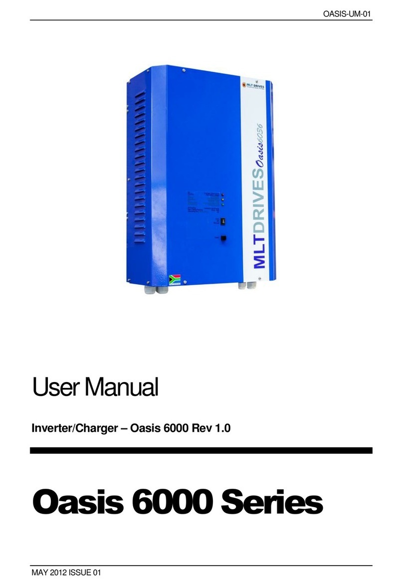
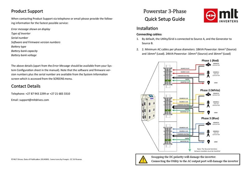
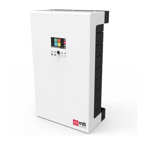
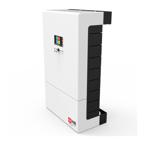
MLT Inverters POWERSTAR 10H Series User guide

+
POWERSTAR 10H
Installer’s Manual

POWERSTAR 10H USER MANUAL PAGE 1
© 2018 MLT Inverters
2nd Edition –May 2020

PAGE 2PS3-UM-06.02.00 POWERSTAR 10 INSTALLER'S MANUAL
Powerstar 10H Series Installer's Manual
Table of Contents
1 Introduction .................................................................................................................................7
1.1 Warnings and cautions .......................................................................................................7
1.2 Contacting MLT Inverters ...................................................................................................8
1.2.1 Product support..........................................................................................................8
1.2.2 Contact details............................................................................................................8
1.2.3 Telephone...................................................................................................................8
1.3 System specifications..........................................................................................................9
1.3.1 AC parameters............................................................................................................9
1.3.2 DC parameters............................................................................................................9
1.3.3 Efficiency.....................................................................................................................9
1.3.4 General......................................................................................................................10
1.3.5 Operator panel / communications..........................................................................10
1.3.6 Altitude derating.......................................................................................................10
1.3.7 Battery bank size requirements...............................................................................11
1.4 System description............................................................................................................11
1.4.1 Typical off-grid or self-consumption application ....................................................12
1.4.2 Typical grid-tied application.....................................................................................12
1.4.3 Basic generator or load control................................................................................12
2 Installation..................................................................................................................................13
2.1 Planning the layout of the machines on site....................................................................14
2.2 Tools required ...................................................................................................................15
2.3 Essential accessories.........................................................................................................16
2.4 Optional accessories .........................................................................................................16
2.5 Mounting the inverter ......................................................................................................17
2.5.1 Mounting considerations.........................................................................................17
2.5.2 Mounting procedure................................................................................................18

POWERSTAR 10H USER MANUAL PAGE 3
2.6 Electrical connections .......................................................................................................20
2.6.1 Making the DC electrical connections.....................................................................21
2.6.2 Making the AC electrical connections.....................................................................22
2.7 Communication wiring......................................................................................................23
2.7.1 The MLT Bus RJ45 socket.........................................................................................24
2.7.2 The ethernet port.....................................................................................................26
2.7.3 Communication between the machines and the battery bank.............................26
2.7.4 Communication between Powerstar 10H’s............................................................26
2.7.5 Communication between Powerstar 10H’s and other MLT machines .................27
2.7.6 Communication between Powerstar 10H’s and MLT Portal .................................27
2.8 External current sensing ...................................................................................................27
2.9 Digital input/output signals ..............................................................................................28
2.9.1 General purpose digital inputs.................................................................................28
2.9.2 Relay-ripple control inputs.......................................................................................28
3 Powering up the Powerstar 10H ..............................................................................................29
4 An introduction to the inverter’s Human Machine Interface ................................................30
4.1 Navigating the touch screen display’s Graphical User Interface ....................................30
4.1.1 The dashboard screen..............................................................................................32
4.1.2 The control screen....................................................................................................32
4.1.3 The charts, logs, and data screen.............................................................................33
4.1.4 The Settings Screen ..................................................................................................34
4.1.5 Screen summary.......................................................................................................36
4.2 Buttons and Switches........................................................................................................37
4.2.1 The On/Off Switch....................................................................................................37
4.2.2 The Start/Stop (and Fault Reset) Button.................................................................37
4.3 The Status LED Indicators .................................................................................................37
4.3.1 The AC Source LED....................................................................................................38
4.3.2 The Inverter LED .......................................................................................................39
4.3.3 The Battery LED ........................................................................................................39

PAGE 4PS3-UM-06.02.00 POWERSTAR 10 INSTALLER'S MANUAL
5 Testing the communication and signal wiring.........................................................................40
5.1 Communication between machines and the Battery Management System................40
5.2 Communication between the inverters and/or solar chargers......................................41
5.2.1 Confirm the device counts on the CAN bus ............................................................41
5.2.2 Confirm the serial numbers and sync messages on all inverters...........................42
5.2.3 Confirm the CAN communication from the MLT Nomads.....................................42
5.3 Testing the internet connection.......................................................................................43
5.4 Testing that the External Current Transformer is wired in correctly..............................44
6 Configuring the machine...........................................................................................................46
6.1 Setting up the “Inverter/Charger Set” .............................................................................46
6.2 Setting up the inverter-AC Supply Interaction.................................................................48
6.3 Setting up the battery configuration for the first time....................................................48
6.3.1 Setting the battery type ...........................................................................................49
6.3.2 Adjusting the Inverter’s Battery Charge/Discharge Settings..................................49
6.4 Setting up alarms and the auxiliary relays.......................................................................54
6.4.1 Setting up the alarms ...............................................................................................55
6.4.2 Muting an alarm .......................................................................................................55
6.4.3 Setting up the auxiliary relays..................................................................................56
7 Starting the machine.................................................................................................................58
7.1 General Instructions..........................................................................................................58
7.2 Three Phase Specific Instructions.....................................................................................58
8 Manual controls.........................................................................................................................60
8.1 Forcing a battery charge...................................................................................................60
8.2 Forcing an auxiliary relay to turn on.................................................................................61
Glossary ................................................................................................................................................62
Appendix A: Single Line Wiring Diagram............................................................................................63

POWERSTAR 10H USER MANUAL PAGE 5
Figures
Figure 1. De-rating the PowerStar inverter output power at high altitude ......................................10
Figure 2. Identifying parts of the Powerstar 10H................................................................................11
Figure 3. A typical layout of a single-phase Powerstar 10H installation showing the inverter (7),
the battery bank (10), the battery cable fuse box (9), the AC Bypass Box (3), and an optional
MPPT.....................................................................................................................................................13
Figure 4. Minimum clearance distances around a unit or between units.........................................15
Figure 5. Permitted mounting orientation..........................................................................................18
Figure 6. Wall mounting.......................................................................................................................19
Figure 7. The AC and DC cable entries on the Powerstar and the location of the On/Off switch.
...............................................................................................................................................................19
Figure 8. A figure showing the AC and DC terminals on the Powerstar and the location of the
PCB socketsusedforCANcommunication,auxiliary relay control,and externalcurrentsensing.
...............................................................................................................................................................20
Figure 9. RJ45 plug pin numbers..........................................................................................................24
Figure 10. An image showing the position of the Powerstar 10H’s touch screen display, the
status LEDs, the start/stop button and the on/off switch..................................................................30
Figure 11. The HMI’s four main screens. Namely the dashboard screen, the control screen, the
charts/info screen, and the settings screen. The navigation bar is shown onthe right side of the
screen. Use the buttons in the navigation bar to move between the screens.................................31
Figure 12. The touch screen display’s screen navigation icons..........................................................31
Figure 13. The HMI’s advanced setup sub-screens. To view the full set of user settings select
the all user settings checkbox. Note most of the settings are passcode protected. To edit a
setting enter the default password (1918) before selecting one of the checkboxes. To access
the advanced table selection screen select the advanced selection checkbox...............................35
Figure 14. An overview of the screens and menus available on the touch screen display..............36
Figure 15. The icons used withthe status LEDs..................................................................................38
Figure 16. The BMS Info screen...........................................................................................................41
Figure 17. The HMI’s Solar Info and Inverter Set screens ..................................................................41
Figure 18. The IP address of the machine is shown on the HMI’s System Info screen. ...................43
Figure 19. An example of MLT Portal’s version of the Dashboard Screen........................................44

PAGE 6PS3-UM-06.02.00 POWERSTAR 10 INSTALLER'S MANUAL
Figure 20. Screenshots showing how to access and edit user settings. From the advanced setup
screen, enter the default passcode (1918), select alluser settings, scroll to the relevant setting,
click edit and then submit the new value...........................................................................................47
Figure 21. Examples of the battery setup screens..............................................................................49
Figure 22. The alarm setup menu........................................................................................................55
Figure 23. The auxiliary relay setup screens. ......................................................................................56
Figure 24. The battery control and relay control screens. .................................................................60

POWERSTAR 10H USER MANUAL PAGE 7
1Introduction
1.1 Warnings and cautions
A safety instruction (message) includes a hazard alert symbol and a signal word, WARNING or
CAUTION. Each signal word has the following meaning:
HIGH VOLTAGE: This symbol indicates the presence of a high voltage. It calls your
attention to items or operations that could be dangerous to yourself or others
operating this equipment. Read the message and follow the instructions carefully.
WARNING:Indicatesapotentially hazardoussituationwhich,ifnotavoided,canresult
in serious injury or death.
CAUTION: Indicates a potentially hazardous situation which, if not avoided, can result
in minor to moderate injury, or serious damage to the product. The situation
described in the CAUTION may, if not avoided, lead to serious results.
GENERAL WARNINGS
DANGER OF ELECTRIC SHOCK.There are no user serviceable parts inside the inverter. DO NOT attempt to make
repairs or alterations to the unit.
WARNING: This equipment should be installed, adjusted, and serviced by qualified electrical maintenance
personnel familiar with the construction and operation of the equipment and the hazards involved. Failure to
observe this precaution could result in personal injury.
GENERAL CAUTIONS
CAUTION: Always wear personal protective equipment (protective clothing, gloves, and safety boots) while
performing an installation or maintenance, to avoid the danger of injuries.
CAUTION: Proper grounds, disconnecting devices, e.g. bypass boxes and other safety devices and their location
are the responsibility of the user and are not provided by MLT Inverters.
CAUTION: Donotcover the device or store it in a small space - always keep it well ventilated and well away from
flammable gases or powders. Components in the device could potentially cause a small electric spark that could
ignite flammable gas or powders. Flammable gases are created by batteries and can become a hazard in poorly
ventilated spaces.
CAUTION: For indoor use only and MUST be installed in a dry area free from conductive liquids or conductive
debris. If part of the inverter becomes submerged in water look for a safe way to isolate it at the distribution
board and if possible at the batteries.

PAGE 8PS3-UM-06.02.00 POWERSTAR 10 INSTALLER'S MANUAL
1.2 Contacting MLT Inverters
1.2.1 Product support
Whencontacting Product Support via telephone, email or fax please provide the following information
for the fastest possible service:
▪Type of Inverter
▪Serial number
▪Battery type
▪Battery bank capacity
▪Battery bank voltage
▪A description of the event
Notethattheserialnumber is available ontheserialplatethatisattachedtothe bottomofthe machine
inside the cover.
1.2.2 Contact details
Telephone:
+27 (0) 21 201 1335
Email:
info@mltinverters.com
Address:
97 Garfield Road
Kenilworth, 7708
Cape Town
South Africa
1.2.3 Telephone
You canreachtechnicalsupport by telephone directly Monday to Thursday between08h00 and 17h00
(GMT +2 hours) and between 08h00 and 15h00 on Fridays. Queries outside of these hours should be
directed to support@mltinverters.com and will be answered at the earliest opportunity. When
contacting technical support, please ensure that you have the information listed above available.

POWERSTAR 10H USER MANUAL PAGE 9
1.3 System specifications
1.3.1 AC parameters
Phases / Rated AC voltage / AC voltage range
1ø / 230 V / 184 to 276 V
Rated frequency / frequency range
50 Hz / 48 to 58 Hz
Rated inverter power (for Unom / fnom / 25°C / cos ɸ=
1)
8 kW
Rated inverteroutput power at 25°C for 30 min when
in stand-alone mode
10 kW
Inverter current (continuous / 20 minutes / 2s)
35 A / 45 A/ 80 A
Rated source current input
63 A
Rated load current output (with grid assist)
63 A
Inverter power factor range (cos ɸ)
+1 to -1
Total Harmonic Distortion (THD)
< 5 %
1.3.2 DC parameters
Nominal battery voltage / range
48 V / 42 V to 63 V
Rated input current (battery discharging) ¹
190 A
Rated / maximum output current (battery charging) ¹
155 A / 190 A
Battery technologies
Lead-Acid, Li-Ion2
Recommended minimum Lead-Acid battery capacity
250 Ah
Lead-Acid charge control
DIN 41773-1 IOuO three-stage charging
with equalisation charge
¹ At 25°C
2Contact MLT Inverters for details on supported Batteries.
1.3.3 Efficiency
Maximum Efficiency
92% stand-alone / 95% with AC connected
No Load Power Consumption (On)
< 60 W
No Load Power Consumption (Standby / Load Sense)
< 8 W

PAGE 10 PS3-UM-06.02.00 POWERSTAR 10 INSTALLER'S MANUAL
1.3.4 General
Mounting Method
Wall Mounted
Dimensions (W x H x D)
400 x 500 x 250 mm
IP/NEMA Rating
IP20 / NEMA1
Colour
white front with black sides
Weight
95 kg
Operating Temperature
-5 to 45 °C (23 to 113 °F)
Architecture
Galvanically Isolated, Forced Air Cooling
1.3.5 Operator panel / communications
Display Type
Full Colour Touch Screen 4.3”LCD; 24h logs of source power, load power,
battery state of charge and Events
Communications
CAN, LAN
All specifications listed above performed at nominal voltage, frequency and temperature unless
otherwise noted.
1.3.6 Altitude derating
Figure 1. De-rating the PowerStar inverter output power at high altitude

POWERSTAR 10H USER MANUAL PAGE 11
1.3.7 Battery bank size requirements
If using a lead-acid battery bank, please ensure that the battery bank size is a minimum of 250 Ah/per
inverter. Having too small a battery bank might cause system instability.
The above value is a guideline and depending on the type and technology of battery, and size of the
load, a larger or smaller bank might be acceptable.
1.4 System description
The Powerstar 10H inverter (see Figure 2) offers a cost-effective and reliable solution to the home or
farm owner faced with unreliable or no grid electricity supply. Each Powerstar unit in a system can
deliver 10 kW for half-an-hour and 8 kW continuously.
The inverter operates at low-voltage DC and is transformer-based, which translates to a robust and
safe product that guarantees trusted power in the harshest environments. The Powerstar inverter
system can be configured in various ways, one of these is with 3 units running as a three phase off-grid
generator. Some other examples include an off-grid installation, a grid-tied installation, and off-grid or
grid-tied with load control. Some of examples of these configurations are given in the following
sections.
Figure 2. Identifying parts of the Powerstar 10H

PAGE 12 PS3-UM-06.02.00 POWERSTAR 10 INSTALLER'S MANUAL
1.4.1 Typical off-grid or self-consumption application
The Powerstar inverter is ideal for off-grid
installations where the renewable source of power is
fed directly into the batteries. The Powerstar
converts the battery power into clean AC power that
the load can use. The built-in battery charging
function allows the use of a backup generator or the
grid without the need for external battery chargers.
1.4.2 Typical grid-tied application
The Powerstar inverter will act as a backup supply to
provide power from the batteries in the event of a grid
failure.
Installing a solar PV inverter on the load side will allow
efficient use of solar energy and any excess generated
power will automatically be used to charge the batteries
or be exported to local loads.
1.4.3 Basic generator or load control
In off-grid systems, the Powerstar inverter can automatically start
the generator when the battery voltage is low or there is high load.
The Powerstar synchronises with the generator before connecting
to it. When the charge cycle is complete, or when the load is low
again, the Powerstar will turn off the generator and transition back
to stand-alone mode.
The Powerstar can also be used to turn specific loads on /offbased onthe battery status or load level.

POWERSTAR 10H USER MANUAL PAGE 13
2Installation
A typical installation will include the inverter/charger, a battery bank, a battery cable fuse box, and an
AC Bypass Box (3). The installation often also includes either some dc-coupled solar chargers or ac-
coupled solar grid-tied inverters. An example of such a system is shownin Figure 3.
For optimalperformance, please refer to the following instructions regarding the installation andsetup
of your Powerstar. A typical Powerstar 10H installation should proceed according to the following
steps:
▪Plan the layout of the inverter(s), the solar chargers, and any relevant accessories (e.g. DC
fuse-boxes and/or the AC bypass box).
▪Mount the inverters and the solar chargers and install any of the relevant accessories.
▪Install the DC and AC cables but leave the machine isolated from any DC or AC supply.
▪Run any necessary machine to machine communicationcables(for example, the CAN cables
between the Battery’s Management System (BMS) and the inverters).
Figure 3. A typical layout of a single-phase Powerstar 10H installation showing the inverter
(7), the battery bank (10), the battery cable fuse box (9), the AC Bypass Box (3), and an
optional MPPT.

PAGE 14 PS3-UM-06.02.00 POWERSTAR 10 INSTALLER'S MANUAL
▪Run any necessary cables necessary for remote monitoring, i.e. LAN cables between the
inverters and the site’s router.
▪Run any of the cables required for any optional sensing or control (for example, external
current sensing or generator control).
▪Power up the inverters and any solar chargers (the Powerstar 10H and MLT’s Nomad Solar
Charger are powered by their battery ports).
▪Confirm that all AC electrical wires, switches and circuit breakers have been installed
correctly.
▪Confirm that the communication betweenthe machines is working.
▪Confirm that the machine has an internet connection.
▪Configure the machines as per the site requirements.
▪Startup the machines.
The following sections go through each of these installations steps as they apply to the Powerstar 10H.
2.1 Planning the layout of the machines on site
The Powerstar 10H is a wallmounted unit with an ingress protection rating of IP20. The unit should be
installed such that:
▪the unit is not exposed to liquids dripping or condensing onto it;
▪the unit is not exposed to excessive dust;
▪theunit is not exposed to direct sunlight;
▪there is adequate ventilation.
A typical single-phase installation is shown in Figure 3. The minimum clearance around a unit (or
between units) is shown Figure 4.

POWERSTAR 10H USER MANUAL PAGE 15
Figure 4. Minimum clearance distances around a unit or between units.
TIP
Itis worth taking some timeto consider the optimal arrangement of the inverters and their
accessories before starting to mount the inverters.
2.2 Tools required
For the installation, one will require the following tools:
▪a drill and masonry drill bits for mounting the machine,
▪an insulated Phillips screwdriver to access the AC and DC terminals, and to secure the AC
cables into their terminals,
▪a socket wrench with an extension and a 17mm socket (or 17mm hinge spanner or T-Handle
wrench) for securing the DC cables,
▪a precision screwdriver set for use with the plugs that plug into the Printed Circuit Board
(PCB), and
▪a RJ45 crimp tool(and cable tester) for making up custom length and pinout communication
cables.

PAGE 16 PS3-UM-06.02.00 POWERSTAR 10 INSTALLER'S MANUAL
2.3 Essential accessories
The following accessories will be required for the installation but are not supplied with the inverter:
▪AC Cables chosen in accordance with the local wiring code,
▪DC Cables chosen in accordance with the local wiring code,
▪Cable lugs to fit the DC cable and the M10 stud used to bolt the batteries cables to the
inverter’s DC terminals,
▪Installation specific protection devices (i.e. circuit breakers, DC fuses) as per the
requirements of the local wiring code.
▪Please note the following:
othe AC source and load ports on the inverter are rated for 63 A,
othe integrated automatic transfer switch is rated for 80 A of resistive load or 30 A
of slightly inductive load (AC-7a),
othe integrated automatic transfer switch is not intended to break short circuit
currents,
osuitably sized circuit breakers should be installed on the inverter’s source side
cables and on its load side cables.
2.4 Optional accessories
The following accessories might be required depending on the configuration of the installation:
▪DC pre-charge circuit (which can be incorporated into the DC cable fuse box),
▪An AC bypass box which can be used to isolate the inverter from the customer’s electrical
installation for the purposes of maintenance.
▪Current Transformers (CTs) for monitoring and controlling power flow at the customer’s
meteringpoint. NOTE: If the CT’s signal is monitored by the Powerstar10H then theCT must
have a nominal a secondary current of 5A and be rated for 2.8 VA or more.
▪Contactors for shedding non-essential loads.
CAUTION: The inverter includes a large capacitor bank on its DC input. If the battery is
connected to the inverter without pre-charging the capacitor bank, the capacitor bank
draws high current as it initially charges up. This high current can cause arcing and/or
pitting at the terminal or fuse that is making the connection.
NOTE: SomeLithium battery brands trip if they detect very high DC current. This can be
solved by the appropriate use of a pre-charge circuit.

POWERSTAR 10H USER MANUAL PAGE 17
2.5 Mounting the inverter
2.5.1 Mounting considerations
Please take note of the following before mounting the inverter:
▪The Powerstar is designed to be wall mounted. A solid support surface must be available for
mounting, e.g. concrete, masonry, or a steel frame.
▪The mounting location must be suitable for the weight and dimensions of the inverter.
▪The mounting location must not be exposed to direct solar irradiation. Direct solar
irradiation can result in the premature aging of the exterior plastic parts of the inverter and
direct solar irradiation can cause the inverter to overheat. When becoming too hot, the
inverter reduces its power output to avoid overheating.
▪The inverter will be de-rated for altitudes above sea-level.
▪The battery leads should be as short as possible, so the Powerstar inverter will need to be
near the batteries.
▪The mounting location must not hinder access to disconnection devices.
▪The mounting location should be freely and safely accessible at all times without the need
for any auxiliary equipment (such as scaffolding or lifting platforms). Non-fulfilment of these
criteria may restrict servicing.
▪The ambient temperature should be below rated operational temperature to ensure
optimum operation.
▪Climatic conditions must be met.
▪The inverter must only be mounted in one of the permitted positions (as shown in Figure 5).
This will ensure that no moisture can penetrate the inverter.
▪The inverter should be mounted in such way that display messages or LED signals can be
read without difficulty and buttons operated.
▪The mounting location must be inaccessible to children.
▪The minimum clearances are shown in Figure 4. A minimum clearance of 125 mm on each
side, the top, and 300 mm from the front must adhered to. If there is more than one unit,
the horizontal distance between them can be 125 mm.
▪A minimum clearance of 300 mm must be kept on the bottom of the inverter. Ideally, the
inverter should be mounted such that the touch screen display is comfortable to use.

PAGE 18 PS3-UM-06.02.00 POWERSTAR 10 INSTALLER'S MANUAL
Figure 5. Permitted mounting orientation.
2.5.2 Mounting procedure
To mount the inverter, proceed as follows.
1. Choose a suitable location. The inverter must only be mounted in one of the permitted
positions.
2. Using a 10 mm masonry drill bit, drill 4 holes using the bracket as a template (Figure 6).
3. Insert the M8 wall anchor bolts through the bracket into the holes, and tighten with a 13
mm spanner, fixing the bracket to the wall.
4. Usingatleasttwopeopleandablock-and-tackle,holdthe Powerstarvertically andliftit onto
the mounting bracket.
Caution: The Powerstar is quite heavy, weighing more than 80 kg; dropping it could
result in personal injury and damage to the machine. It recommended that mounting
the inverter be performed by a minimum of two people, using a mechanical block-
and-tackle.

POWERSTAR 10H USER MANUAL PAGE 19
Figure 6. Wall mounting
Figure 7. The AC and DC cable entries on the Powerstar and the location of the On/Off switch.
Table of contents
Other MLT Inverters Inverter manuals
Popular Inverter manuals by other brands

Covidien
Covidien VNUS RFG2 Operator's manual

solarwatt
solarwatt MyReserve Cluster Installation and integration

Power Craft
Power Craft PGG-800 Original instructions & warranty

WESTECH
WESTECH Solax X3-HYBRID G4 manual

Ningbo Genin Industrial
Ningbo Genin Industrial 0503GGT007 operating instructions

Sungrow
Sungrow SG2.0RS-S user manual

One Inverter
One Inverter GSI-152 Operational manual

Solaro Energy
Solaro Energy Solaro Aire SA-20WR-GAE installation instructions

Winco
Winco W10000VE/A Installation and operator's manual

Beko
Beko BEHPI 090 owner's manual

Mitsubishi Electric
Mitsubishi Electric FR-PU07 instruction manual

Siemens
Siemens SINAMICS G120 operating instructions