Mobileye 5 User manual

Technical Support
Mobileye 5 –Technical Installation Guide_Rev 0.3
Jan, 2012
Page 1 of 38

Technical Support
Mobileye 5 –Technical Installation Guide_Rev 0.3
Jan, 2012
Page 2 of 38
Mobileye Proprietary and Confidential
Every effort has been made to ensure the accuracy of all information in this
Technical Installation Guide. However, Mobileye Technologies Limited makes no
expressed or implied warranty or representation based on the enclosed information.
Mobileye Technologies Limited reserves the rights to alter the equipment
specifications and descriptions in this publication without prior notice. Any errors or
omissions may be reported to Technical Support, Mobileye Technologies Limited.
© 2007-2011 Mobileye Technologies Limited. All rights reserved.
Reproduction in whole or in part without written permission is prohibited.
Mobileye, Mobileye AWS, Mobileye C2, Mobileye 5 and the Mobileye logo are
registered trademarks of Mobileye Technologies Ltd.
www.mobileye.com

Technical Support
Mobileye 5 –Technical Installation Guide_Rev 0.3
Jan, 2012
Page 3 of 38
Mobileye Proprietary and Confidential
Table of Contents
1Warnings....................................................................................................... 5
1.1 General...........................................................................................................5
1.2 System Limitations .........................................................................................5
1.3 Installation and Safety Instructions ...............................................................6
2Mobileye 5 Description.................................................................................. 7
2.1 Mobileye 5 Components overview.................................................................7
2.1.1 Mobileye 5 Main Unit & connecting cable (CAB000105) ..........................7
2.1.2 EyeWatch - Display & Control unit (CAB000087) ......................................8
2.1.3 External Fuse Holder..................................................................................8
2.1.4 3M VHB Surface Cleaner............................................................................9
2.1.5 Mobileye 5 Connection Scheme ................................................................9
2.2 Mobileye 5 Connections Description............................................................10
2.2.1 Mobileye 5 Main unit connections ..........................................................10
2.2.2 External Fuse Holder & 2A Fuse...............................................................11
2.2.3 EyeWatch –Display & Control unit connection (optional)......................11
2.2.4 EyeCAN –Mobileye CAN to USB interface ..............................................11
3Mobileye 5 Installation.................................................................................12
3.1 Electrical Vehicle Signals Requirements.......................................................12
3.2 Mobileye 5 Installation Procedure ...............................................................13
3.2.1 Mobileye 5 Connection Scheme ..............................................................14
3.2.2 Connecting to Vehicle Signals ..................................................................14
3.2.3 Installing the EyeWatch (optional) ..........................................................15
3.2.4 Installing the Mobileye 5 Main Unit (Camera) ........................................16
4System Calibration Procedure.......................................................................20
4.1 Removing the Mobileye 5 Back Covers ........................................................20
4.2 Adjusting the Camera Angle ........................................................................24
4.3 Mobileye Setup Wizard –Calibration ..........................................................26
4.3.1 Local Information.....................................................................................26
4.3.2 Car Information........................................................................................27
4.3.3 Car Hood Step ..........................................................................................28

Technical Support
Mobileye 5 –Technical Installation Guide_Rev 0.3
Jan, 2012
Page 4 of 38
Mobileye Proprietary and Confidential
4.3.4 Actual Camera Position............................................................................29
4.3.5 Signals Source ..........................................................................................31
4.3.6 Signals polarity Configuration..................................................................32
4.3.7 Camera Calibration ..................................................................................32
4.3.8 Signal Test & Configuration .....................................................................35
4.3.9 Test Drive .................................................................................................36
5Appendix A...................................................................................................38
5.1 Parameter error significance and functionality implications.......................38
Camera height..........................................................................................................38
Lateral distance to the front wheels ........................................................................38
Distance to the front of the vehicle..........................................................................38

Technical Support
Mobileye 5 –Technical Installation Guide_Rev 0.3
Jan, 2012
Page 5 of 38
Mobileye Proprietary and Confidential
1Warnings
1.1 General
By Installing the Mobileye®5®Driver Assistance System, you will be acknowledging
and agreeing to operate Mobileye 5 in accordance with the Safety Instructions and
Warnings set forth below. If you do not agree to these terms, please return
Mobileye 5 to your dealer, in its original packing materials, within 30 days of
purchase, for a full refund.
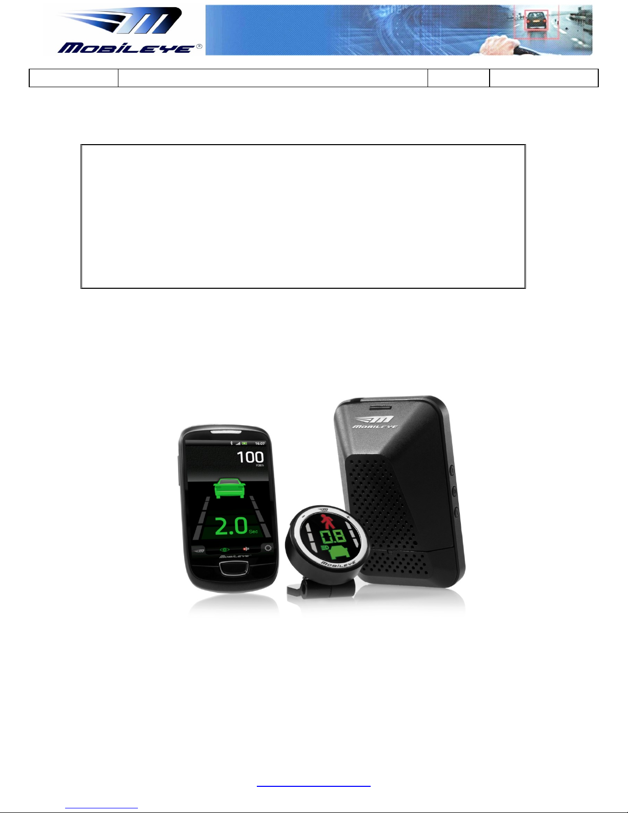
Mobileye 5 is a driver assistance system which is intended to alert drivers to certain
potentially dangerous situations. It does not replace any functions drivers would
ordinarily perform in driving a motor vehicle, nor does it decrease the need for
drivers to stay vigilant and alert in all driving conditions, to conform to all safe driving
standards and practices, and to obey all traffic laws, rules and regulations.
Mobileye 5 is not an automated driving system and it does not act as a substitute for
any aspect of driver vehicle control or safe driving practices. Drivers are strongly
cautioned not to rely on the Mobileye 5 as a substitution, to even the slightest
degree, for the exercise of due caution in assuring that they are driving safely and
avoiding accidents.
While Mobileye 5 represents a state of the art innovation in machine vision software
and other technologies, it cannot and does not guarantee 100% accuracy in the
detection of vehicles or driving lanes, nor in providing warnings of all potential road
hazards. Mobileye 5 system’s recognition and response capabilities. Accordingly,
drivers should not rely on the Mobileye 5 to assure their driving safety, but rather
should continue to rely on safe driving practices.
Drivers should exercise caution in using the Mobileye 5 Display Unit. Always maintain
full concentration on the road at all times including while looking at the Mobileye 5
display
1.2 System Limitations
The Mobileye 5 is intended for paved roads, with clear lane markings.
The Mobileye 5 only detects fully visible rear ends of vehicles (Day and Night) and
fully visible pedestrians and rear ends of Motorcycles (Day only). Therefore the
detection of crossing, oncoming, and passing vehicles is not supported.
The Mobileye 5 does not guarantee 100% accuracy in the detection of vehicles or
driving lanes, nor in providing warnings of all potential road hazards. In addition,

Technical Support
Mobileye 5 –Technical Installation Guide_Rev 0.3
Jan, 2012
Page 6 of 38
Mobileye Proprietary and Confidential
road, weather and other conditions can adversely affect the Mobileye 5 system’s
recognition and response capabilities.
Any conditions that form partial or full blockage of the camera’s view will result in
reduced or non-functionality of Mobileye 5. Always ensure clear camera view.
1.3 Installation and Safety Instructions
Mobileye 5 installation must be carried out by an Authorized Mobileye 5 Dealer or
Installer.
The Mobileye 5 system should not be transferred between vehicles, other than by an
Authorized Mobileye 5 Dealer or Installer.
The Mobileye 5 should only be operated with 12VDC~24VDC power.
Do not cover or obstruct the Camera Unit or Mobileye 5 Display and Control Unit.
Only proper tools are to be used.
Only L.E.D voltage tester or Digital Multi Meter should be used.
The use of light bulb voltage tester is prohibited.
Pay attention to unusual color cables for example: Yellow cable isolation belongs to
air bags; two twisted wires usually belong to different sensors (digital).
Before disconnecting the battery or the radio connectors make sure to have the
radio code.
Do not disconnect any plug or connector in the vehicle when the ignition switch is
turned on.
NOTE:
Mobileye 5®installation is possible only on CAN-bus supported vehicles.
Minimum CAN-bus signals required for Mobileye 5 installation:
- Speed
- Left & Right Indicators (Blinkers)

Technical Support
Mobileye 5 –Technical Installation Guide_Rev 0.3
Jan, 2012
Page 7 of 38
Mobileye Proprietary and Confidential
2Mobileye 5 Description
WARNING: The Mobileye 5™ system should be installed ONLY by Mobileye® Technologies Ltd.
authorized personnel!
2.1 Mobileye 5 Components overview
The Mobileye 5is based on the following elements:
The Mobileye 5 Main Unit and Connector Cable (Camera)
The EyeWatch Display & Control Unit (Optional)
When receiving the Mobileye 5 please verify receiving & identify all the following
components:
2.1.1 Mobileye 5 Main Unit & connecting cable (CAB000105)
The Mobileye 5 Main Unit contains the following components:
Camera unit, High-quality Audio Alert Buzzer, Mobileye Chip on Board system
(SeeQ), Connector Cable.
Figure 1: Mobileye 5 with connecting cable –Front view.

Technical Support
Mobileye 5 –Technical Installation Guide_Rev 0.3
Jan, 2012
Page 8 of 38
Mobileye Proprietary and Confidential
2.1.2 EyeWatch - Display & Control unit (CAB000087)
Figure 2: EyeWatch Display and Control Unit with connecting cable
2.1.3 External Fuse Holder
The Mobileye 5 is supplied with an External Fuse Holder and a 2A Fuse for
protection against short circuiting the vehicle electrical system.
Figure 3: External Fuse Holder & 2A Fuse
NOTE: The EyeWatch Display and Control Unit is sold as an optional add-on on certain
Mobileye 5 models. Mobileye 5 can also be used with an Android based Bluetooth
device (Smart Phone) for displaying Mobileye 5 Alerts.

Technical Support
Mobileye 5 –Technical Installation Guide_Rev 0.3
Jan, 2012
Page 9 of 38
Mobileye Proprietary and Confidential
2.1.4 3M VHB Surface Cleaner
The 3M VHB Surface Cleaner supplied with Mobileye 5 Cleans and degreases the
Windshield surface to ensure optimum adhesion for 3M VHB Tape provided with the
Mobileye 5 Main Unit.
Figure 4: 3M VHB Surface Cleaner
2.1.5 Mobileye 5 Connection Scheme
Figure 5: Mobileye 5 connection scheme with EyeCAN

Technical Support
Mobileye 5 –Technical Installation Guide_Rev 0.3
Jan, 2012
Page 10 of 38
Mobileye Proprietary and Confidential
2.2 Mobileye 5 Connections Description
The following paragraphs describe in detail the function of the cables and
connections shown above.
2.2.1 Mobileye 5 Main unit connections
The Mobileye 5 main unit contains the camera, the Audio Buzzer and the main
processor (EyeQ™). The Mobileye 5 main unit also contains volume control buttons.
The Mobileye 5 Main unit functions as a Universal Mounting Adapter for all vehicles’
front windshield angles. It is attached to the vehicle’s front windshield with the
provided 3M double sided sticker.
The Mobileye 5 Connecting cable is split into a few various cables which are used to
connect to the vehicle power source, to the vehicle CAN-bus, to the vehicle High-
beams (for IHC) and to the Mobileye EyeWatch display and Control unit and
Mobileye EyeCAN.
A detailed description of each Mobileye 5 connecting cable connections can be
found in the table below:
Wire Name & Function
Wire color
Connector
Connection To
EyeCAN - ( 6 pin connector)
Black
P2
EyeCAN unit (for system calibration)
EyeWatch - (4 pin connector)
Black
J1
EyeWatch Display & Control unit
BAT+ (12/24V)
Red
-
Vehicle constant power (Battery)
GND
Black
-
Vehicle GND (BAT-)
Ignition (12/24V)
Blue
-
Vehicle Ignition signal
CAN B H
White
-
Vehicle CAN-bus (CAN High wire)
CAN B L
Yellow
-
Vehicle CAN-bus (CAN Low wire)
IHC –(Analog Output)
Gray
-
Vehicle High-beams via external Relay
AUX
Pink
-
Future option
Table 1: Mobileye 5 connecting cable connections

Technical Support
Mobileye 5 –Technical Installation Guide_Rev 0.3
Jan, 2012
Page 11 of 38
Mobileye Proprietary and Confidential
2.2.2 External Fuse Holder & 2A Fuse
The External Fuse Holder connection is as follows
1. Cut the fuse holder cable so that it creates 2 separate wires
2. Connect one end of the Fuse holder to the Vehicle Power source (12V/24V).
3. Connect one end of the Fuse wire to the Mobileye Power Cable (Red wire).
2.2.3 EyeWatch –Display & Control unit connection (optional)
The EyeWatch is supplied only on certain Mobileye 5 models. The EyeWatch is
connected to the Mobileye 5 EyeWatch Female connector (J1) using the EyeWatch
connecting cable Male connector (J1).
Wire Name
Wire color
Connector
Connection To
EyeWatch Cable (CAB000087)
Black
J1 - male
Mobileye 5 cable - EyeWatch connector
EyeWatch - (CAB000105)
Black
J1- female
EyeWatch Display & Control unit
Table 2: EyeWatch connections
2.2.4 EyeCAN –Mobileye CAN to USB interface
The EyeCAN is NOT part of the Mobileye 5 system. It is a tool which enables the
installer to configure and calibrate the Mobileye 5 system during the installation. The
Mobileye 5 EyeCAN Male connector (P2) is used for connection with the Mobileye
EyeCAN Box Female connector labeled “CAN” (J5).
Wire Name
Wire color
Connector
Connection To
CAN (EyeCAN box connector)
Black
J5 - female
Mobileye 5 cable - EyeCAN connector
EyeCAN - (CAB000105)
Black
J1- Male
EyeCAN box connector labeled “CAN”
Table 3: EyeCAN connections

Technical Support
Mobileye 5 –Technical Installation Guide_Rev 0.3
Jan, 2012
Page 12 of 38
Mobileye Proprietary and Confidential
3 Mobileye 5 Installation
3.1 Electrical Vehicle Signals Requirements
Table 4 details the Mobileye 5 requirements regarding which vehicle signals are
needed, and what their electrical attributes should be.
Please make sure the vehicle to-be-installed complies with these requirements
Item
Description
Value
Signals Cables
Car inputs
BAT+, GND, Ignition, High Beam, CAN-Bus
(High/Low)
Voltages
Input
12 - 36VDC
Current Load (full operation)
12v > 360mA, 24v > 180mA**
Stand-by Current Load (Ignition off)
12v > 10mA, 24v > 10mA
Power consumption
Nominal 5.2W
* A 12V vehicle has battery voltage of 13.7V and 24V vehicle has battery voltage of 27V.
** The current consumption of the Mobileye 5 is depended on the vehicle system voltage (12 or 24V).
Additional Notes:
1. Mobileye 5 complies with automotive standard (ISO-7637-2) regarding voltage transients for all
signals (input voltage and car signals).

Technical Support
Mobileye 5 –Technical Installation Guide_Rev 0.3
Jan, 2012
Page 13 of 38
Mobileye Proprietary and Confidential
3.2 Mobileye 5 Installation Procedure
The following chart summarizes the main stages of the Mobileye 5 installation
procedure:

Technical Support
Mobileye 5 –Technical Installation Guide_Rev 0.3
Jan, 2012
Page 14 of 38
Mobileye Proprietary and Confidential
3.2.1 Mobileye 5 Connection Scheme
Please ensure that you identify the Mobileye 5 cables according to diagram below.
The paragraphs that follow will present the function of each cable, and then guide
you through their actual connection procedures with the car signals.
3.2.2 Connecting to Vehicle Signals
CAUTION: Identifying the vehicle’s electrical signals requires having the keys in the
ignition in the ACC (Accessory) position or Ignition ON. Make sure the car
headlights and/or any other power consuming devices are turned off during
Mobileye 5 installation to prevent battery drainage.
1. Identify the wires in the vehicle that carry the required electrical signals
(according to table below).
2. After identifying the required signals locations in the vehicle, pass the
Mobileye 5 cable (CAB000105) behind the vehicle trimmings so that it
reaches all vehicle signals (it is recommended to hang the Mobileye 5 Main

Technical Support
Mobileye 5 –Technical Installation Guide_Rev 0.3
Jan, 2012
Page 15 of 38
Mobileye Proprietary and Confidential
Unit on the rear view mirror or place it on the dashboard before passing the
cable behind the vehicle trimmings).
3. Firmly connect the appropriate wire from the Mobileye 5 (CAB000105) to the
identified vehicle signal.
Each wire in the Mobileye 5 cable mentioned above has a unique color.
Make sure to connect the correct vehicle signal to its appropriate wire
according to Table 2-7.
Identified vehicle signal
Wire label
Wire color
Vehicle battery (Constant 12V~24V) via 2A Fuse
BAT+
Red
Ignition (12V~24V)
Ignition
Blue
Vehicle GND
GND
Black
CAN High
CAN High
White
CAN low
CAN low
Yellow
NOTE: Make sure the 2A fuse is kept easily accessible
NOTE: Wires’ colors are not guaranteed. Always refer to the wires’ labels
NOTE: Always check the Mobileye Internal Database for CAN-Bus availability before
installation is started
4. Keep the Mobileye 5 EyeCAN and EyeWatch connectors easily accessible.
3.2.3 Installing the EyeWatch (optional)
1. Select the optimal location for the EyeWatch. The unit should be placed on
the dashboard at a location which is in the driver's field of view and
convenient for him to see when driving, and to allow him access to the
controls while seating comfortably in the driver's seat (the EyeWatch
mounting angle is adjustable by the installer, a Philips screw driver is
required).
2. Clean the selected location with the provided 3M VHB Surface cleaner.
3. Attach the EyeWatch to the selected area (remove the protective cover from
the adhesive tape).
4. Remove transparent protecting cover from the display surface

Technical Support
Mobileye 5 –Technical Installation Guide_Rev 0.3
Jan, 2012
Page 16 of 38
Mobileye Proprietary and Confidential
5. Insert the EyeWatch cable (CAB000087) behind the vehicle the trimmings so
that it reaches the EyeWatch connector of the Mobileye 5 cable (CAB000105).
WARNINGS!
- The EyeWatch and Main Unit should be placed in a location that does not obstruct
the driver’s field of view.
-The EyeWatch should not be placed in front of air-bags operational space. The unit
may prevent the air-bag from fully opening and/or may cause injury during air-bag
activation.
-Attaching the EyeWatch on the Vehicle’s windshield is not recommended
(EyeWatch may overheat).
3.2.4 Installing the Mobileye 5 Main Unit (Camera)
3.2.4.1 Selecting the optimal location for the Main Unit:
Select the optimal location for the Main Unit. Please comply with the following
requirements as incorrect positioning may affect the overall performance of the
system.
The Main Unit should preferably be placed at the top of the
windshield (preferably at a height over 1.2 meter), in an area
well covered by the windshield wipers.
The Main Unit should be placed at approximately the center
of the vehicle widthwise. If this is not possible it should be
within the central third of the vehicle width. It should be
noted that some car models have convex windshield
(sideways), which intensifies the problem of an off-center
installation.
The validation to the windshield edges allows an offset up to
25cm only. The preferable position of the Main Unit is in the
middle of the windshield. If this is not possible we allow up to
25 cm offset to one of the sides but no more so to not cause
reduction in system performance.
There should be no occlusions such as stickers or darkened
windshield areas in front of the Main Unit.

Technical Support
Mobileye 5 –Technical Installation Guide_Rev 0.3
Jan, 2012
Page 17 of 38
Mobileye Proprietary and Confidential
In tall commercial vehicles that do not have an engine hood
occluding the field of view of the camera, the v Main Unit can
be placed on the lower part of the windshield, while
considering all of the above-mentioned requirements. In this
case, you can modify the Main Unit cable to the "DOWN"
position. “DOWN” means that after the Main Unit installation,
the Main Unit cable exits the Main Unit downwards, instead of
upwards (which is the case in the default “UP” position.
3.2.4.2 Attaching the Camera to the Windshield
1. Before starting the Main Unit installation, make sure that the car is not
loaded with unusual heavy cargo that can tilt the orientation of the car body.
2. Make sure the vehicle is standing on a flat surface with no side or forward
slope.
3. Clean the intended installation location on the windshield using the 3M VHB
Surface Cleaner to remove oily or other remains.
4. Wipe the installation area on the windshield by thoroughly using a dry wipe
(important since the 3M VHB Surface Cleaner that removes oily substances
may leave marks on the windshield that will obstruct the camera’s field of
view)

Technical Support
Mobileye 5 –Technical Installation Guide_Rev 0.3
Jan, 2012
Page 18 of 38
Mobileye Proprietary and Confidential
5. Connect the Mobileye 5 EyeCAN cable (6 pin male connector –CAB000105)
to the EyeCAN Unit (6 pin Female connector labeled “CAN”).
6. Connect the EyeCAN unit USB connector to the Laptop Computer USB port.
Mobileye 5
EyeCAN
Laptop PC
Connector
Connector
Connector
6 pin male
6 pin Female
USB
USB
7. Power On the laptop computer.
8. Power on the Mobileye 5 system by turning on the vehicle ignition switch to
ACC (Accessory) position.
9. Run the Mobileye Setup Wizard Application
10.After connecting successfully, you should see the Camera image in the “Camera
Installation” window of the Mobileye Setup Wizard.
NOTE: Chose the vehicle from the Internal Database in the Mobileye Setup Wizard
application before continuing (see Appendix F for more details).

Technical Support
Mobileye 5 –Technical Installation Guide_Rev 0.3
Jan, 2012
Page 19 of 38
Mobileye Proprietary and Confidential
11.Locate the “TAC Target” exactly in the middle of the vehicle’s front bumper
(for cars –close as possible to the front bumper, for trucks –1 meter away from
front bumper )
12.Using the image feed (camera installation slide) start gluing the Camera from
the top down, maintaining the horizontal lines in the scene ahead as the
horizontal lines in the image window. When completed, firmly attach the
camera to the windshield.
NOTE: Before attaching the Main Unit verify there is enough room to dismantle the
Main Unit back covers using a small Philips screw driver.
NOTE: For Truck and Bus installations first remove the Mail Unit back covers, Slide
the Camera Down the railing to Level 6 and then follow steps 5 to 12.
The image below shows the Main Unit (Camera) attached to the front windshield,
typically behind the rear view mirror. The Green L.E.D on the back of the Main Unit
indicates that the Mobileye 5 is receiving power.
Figure 1-10 Vision Sensor Unit located on the windshield behind the rear view mirror
NOTE: At the end of this process, all the system components are connected and all
Mobileye 5 components are attached to the vehicle and connected to the Laptop PC

Technical Support
Mobileye 5 –Technical Installation Guide_Rev 0.3
Jan, 2012
Page 20 of 38
Mobileye Proprietary and Confidential
4 System Calibration Procedure
CAUTION: When Performing System Calibration DO NOT:
- Disconnect the EyeWatch connection
- Move the laptop carelessly
- Turn off the vehicle or in any other way turn off power to the Mobileye 5 system
4.1 Removing the Mobileye 5 Back Covers
In order to calibrate the Mobileye 5, the camera angle must be set prior to the
calibration process. To access the camera adjustment screw there is a need to
remove the Mobileye 5 Main Unit Back Covers.
To remove the Main Unit Back Covers follow the below instructions:
1. Insert a small screw driver at the slightly larger circles at the right and Left
ends of the lower part of the Main Unit Back Cover and press the bracket to
release.
Table of contents
Other Mobileye Automobile Accessories manuals

Mobileye
Mobileye Mobileye 6 User manual

Mobileye
Mobileye AWS-4000 User manual

Mobileye
Mobileye 530 User manual

Mobileye
Mobileye C2-270 User manual

Mobileye
Mobileye Mobileye 6 User manual

Mobileye
Mobileye AWS-4000 User manual

Mobileye
Mobileye Mobileye 6 User manual

Mobileye
Mobileye C2-270 User manual

Mobileye
Mobileye 8 Connect Manual

Mobileye
Mobileye 550 User manual