Mobility Research LITEGAIT II User manual


Dear User,
CONGRATULATIONS on your recent purchase of LiteGait II, the most innovative gait
and balance training system available today. As you know, LiteGait can be used with
a wide variety of patient impairment levels and conditions. If you have questions
about the possible uses of LiteGait with particular patients, or are in need of some
ideas for ways to use LiteGait more effectively, please do not hesitate to contact us
for information relating to your individual situation. Our website also offers valuable
information.
Like all quality therapy equipment, LiteGait requires regular inspections. Enclosed is
a check list for your convenience. Please complete the check list every 6 months to
ensure the efficient, safe, and effective operation of the LiteGait unit. If you should
find a problem with a LiteGait part, please contact the Technical Support Department
immediately. Here are some phone numbers which will be of help to you:
TECHNICAL SUPPORT & SERVICE: 480-829-1727
SALES: 800-332-9255
Website: www.LiteGait.com
Sincerely,
Customer Service Department
Mobility Research


ABOUT YOUR UNIT 6
ASSEMBLY DIAGRAM 7
UNIT ASSEMBLY 8
USING LiteGait1 10
UNIT AND HARNESS CARE 19
PARTS DIAGRAM / LIST 20
MAINTENANCE CHECK 23
RESOURCE DIRECTORY 27
WARRANTY INFORMATION 28
TABLE OF CONTENTS
TROUBLE SHOOTING 25

6
ABOUTYOUR UNIT
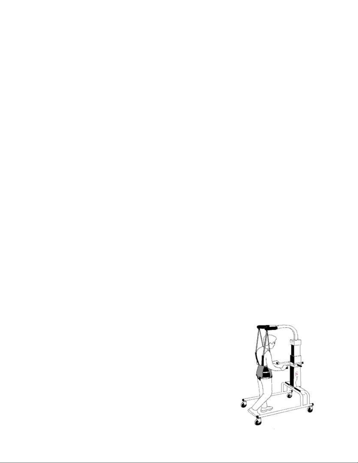
LiteGait II consists of several parts (for diagram see next page):
1. YOKE: The yoke is a bent Y-shaped piece that has four female buckles at the ends. The yoke
slides over the mid-post and is height adjustable. Be certain to securely tighten the L-shaped or
round knobs, locking the yoke into place before connecting the patient. In addition, the units come
with a spring loaded ball/pin mechanism that will assist in locking the yoke in place at different
heights. ALWAYS TIGHTEN THE KNOBS IN ADDITION TO USING THE BALL/PIN MECHANISM.
2. OVERHEAD STRAPS: The overhead straps consist of a set of four straps with male connectors
at both ends. Overhead straps connect to the yoke and harness, providing postural support for the
patient. The straps also allow adjustments to be made in relation to the amount of weight bearing
load supported by the unit.
3. HARNESS & GROIN PIECE: The harness is an adjustable wrap with a buckle closure in the front
and three adjustable straps on each side. There are four female connectors at the top of the
harness that attach to the male buckles of the overhead straps. The four female buckles at the
bottom of the harness allow for the connection of the groin piece. The H-shaped stitching on the
groin piece denotes the top or body side of the piece.
4. MID-POST: The center column, or mid-post, attaches to the base with 4 bolts. Both the
handlebars and the yoke slide over the mid-post and are clamped into place at the desired height.
The yoke also has a spring loaded ball/pin mechanism that locks in place on the mid-post.
5. HANDLEBAR: The handlebar assembly consists of 2 parallel arms which are attached to a plate
with round clamping knobs. It slides over the mid-post and is height adjustable. Be sure to tighten
the round clamping knobs securely, locking the handlebar into place before using. Never allow the
patient to hang directly from the handlebars.
6. BASE: The base consists of two horizontal bars connected by two U-shaped tubes. The base
has an open end and a closed end where the mid-post is attached. The base moves freely over
ground, or can be locked into place during use over a treadmill. Be certain to lock all caster brakes
when using the unit over a treadmill or when connecting the patient to the unit. Never leave a
patient unattended in the unit.
7. CASTERS: Four casters with locks are attached to the base. The two caster locks on one side
of the base are brakes and the two on the opposite side are directional locks.

7
7
CASTERS
1
YOKE
4
MID-POST
2
OVERHEAD
STRAPS
3
HARNESS &
GROIN PIECE
5
HANDLEBAR
6
BASE
LiteGait II Assembly Diagram

8
UNIT ASSEMBLY
Tools needed for unit assembly: Utility knife, 7/32 inch allen wrench, and two people
ASSEMBLY INSTRUCTIONS:
1. Open the carton carefully, using a utility knife to cut the tape that holds the box closed.
2. Carefully cut all strapping material holding the various pieces in place.
3. Take extra care not to damage the paint or any of the material covering the various parts.
4. Once all parts are separated, remove the base from the box, placing it on a level floor.
5. Lock the locking casters (found at the open end of the LiteGait II) and remove the bolts from the top
plate on the base.
6. Remove the mid-post and yoke assembly together from the box.
7. Loosen the knobs (L-shaped or round) holding the yoke in place. Pull back on the ball/pin
mechanism and hold while moving the yoke along the mid-post.
8. Slide the yoke up and remove it from the mid-post.
MID-POST ASSEMBLY:
9. Lift the mid-post section and gently place it on the top plate of the base.
10. Align the bolt holes on the mid-post with the holes on the base.
11. Place the bolts through the holes and into the base.
12. Hand tighten all four attaching bolts as far as possible.
13. Use a 7/32’’ allen wrench to lightly tighten each bolt, then go back and tighten each bolt again.
14. Ensure that all four bolts are secure upon completion.

9
Handlebar Assembly (only if not attached upon receipt):
16. To attach the handlebar, loosen the two round knobs from the rear of the handlebar assembly. (Hold the
handlebar so that the round knobs are at the top of the handlebar assembly. See picture).
17. Slide the handlebar down the mid-post keeping the arms in line with the legs of the base.
18. Raise or lower the handlebar as desired.
19. Tighten the two round knobs to securely hold the handlebar at the desired height.
Yoke Assembly:
20. To attach the yoke, slide the yoke down the mid-post.
21. The extending arms of the yoke should point in the same direction as the arms of the handlebar and the
legs of the base.
22. Pull back on the ball of the ball/pin mechanism in order to move the yoke up and down the post. When
released, the pin portion will insert into one of the guide holes along the length of the mid-post. This is
an additional safety measure and should always be used in conjunction with tightening the knobs (L-
shaped or round).
23. Raise or lower the yoke to the desired height.
24. The yoke should be positioned above the patient’s head.
25. Tighten both knobs to securely lock the yoke at the desired height.
26. The knobs should only be turned 1/2 a turn to loosen or tighten.
Overhead Straps:
27. Attach the four overhead straps into the yoke buckles.
28. The adjustable buckles attach to the yoke.
29. The fixed buckles will later connect to the harness.
Your Unit Is Now Fully Assembled.
UNIT ASSEMBLY

10
I. Casters
LiteGait is equipped with four casters. There are two total locking casters and two directional lock
casters. Each leg has one type of caster. Directional lock casters have a black brake lever. Total
locking casters have a chrome brake lever.
How to lock the caster brakes
Depress the caster brake on all four casters. The caster brakes should be locked whenever the
LiteGait is not being moved over the ground.
1. Position LiteGaitnear the treadmill (or where you wish the patient to
begin walking).
2. Roll LiteGaittoward the front of the treadmill, until the casters line up parallel to the treadmill (or
parallel to the path the patient will follow—over ground, for example).
3. Depress the directional locks. This will prevent the caster from pivoting.
4. LiteGait can now be easily rolled back and forth over the treadmill or on a straight path in the
therapy room or hallway.
5. When using over a treadmill, all four caster brakes need to be pressed.
CAUTION: While locking the casters prevents rolling of the unit, it does not prevent the unit
from sliding on a sloped, slippery floor. The unit should only be used on a flat floor and away
from stairs and ramps. NEVER leave a patient unattended in the unit.
Directional Lock Casters
Directional lock casters facilitate rolling the device back and forth over a
treadmill and help keep the LiteGait straight while performing therapy
over ground (walking down a hallway, for example). The directional lock
casters have a black brake.
NOTE: When walking patients overground, first establish the direction of movement, then
lock the directional casters to ensure the best performance. To move in the opposite
direction, release the caster brakes and re-establish the direction of movement. That is,
allow the casters to follow the movement rather than lead it.
BRAKE
USING LiteGait II
Note: The casters on your unit are designed to provide a safe, secure lock that prevents
rolling while the unit is in place. The caster brakes should be locked any time the unit is not
being moved.

11
II. HARNESS APPLICATION TIPS
How to put on the harness
The harness was designed to support a patient in an upright position, allowing for full hip extension. This
upright posture plays a critical role in the effectiveness of the gait therapy performed with partial weight
bearing.
The front of the harness wrap refers to the point at which the two ends of the harness meet. The harness can
be worn with the closure either in the front or in the back. There are four buckles on the top and bottom of the
harness wrap. The four top buckles extend beyond the harness from the top seam and attach to the
overhead straps. The bottom four buckles attach to the groin piece and do not extend past the bottom seam
of the harness.
Harness and groin piece preparation
1. Pick the appropriate harness and groin piece for the patient.
2. Estimate the harness girth before placing on the patient by folding the harness in half. Then, hold
the harness in front of the torso to estimate the width from one side of the body to the other.
3. Estimate the groin piece size by looking at the patient's groin width from front to back
4. Tighten or loosen the 3 rows of side straps on each side of the harness. (To loosen the side
straps lightly pull up on the black tabs on the side buckles.)
5. Keep the harness folded in half and align the top buckles so that they are adjacent with each
other.
6. Take the groin piece and adjust the groin strap padding toward the center of the strap before
putting it on.
7. Adjust the front groin straps so they are equal in length.
8. Adjust the back groin straps so they are equal in length.
9. Attach the groin piece to the back of the harness.
10.The seamed side of the groin piece (most padded) will go against the patient’s body.
USING LiteGait II

12
Figure 1 Figure 2
Figure 3 Figure 4
Figure 5 Figure 6
USING LiteGait II

13
Tightening The Side Straps
14. Tighten the lower side straps first, as symmetrically as possible. These straps are crucial to
the proper distribution of the patient’s weight, and should be as tight as possible.To ensure a
snug fit, pull the strap closest (Figure 2) to the body towards its black plastic buckle with one
hand while pulling the free end with your other hand until you cannot pull anymore.
15.Tighten the other two side straps by pulling on each one. Make sure to tighten both sides
symmetrically (equally) so that an equal strap length remains on each side. These should be as
tight as the patient can tolerate without discomfort. The top strap should not interfere with
breathing. Bulges of fatty tissue should be apparent (visible on most patients) as the harness is
tightened. These bulges are very important and will allow the harness to securely grab onto the
soft tissue of the abdomen, keeping the harness securely in place throughout the training.
Groin piece attachment
16.Attach the groin piece to the front harness buckles. (The stitched side of the groin piece should
be facing up against the body, see Figure 3.)
17.Hold the padded part of one end of the groin piece with one hand.
18.Pull it against the patient’s leg. Keep holding it while the other hand pulls the free end of the
groin strap. (Figure 4)
19.Tighten the groin strap snugly so there is NO slack.
20.Repeat on the other side.
21.Tug on the patient's pant legs to remove any wrinkles or bulges.
22.Sit the patient up or stand the patient if safe
NOTE: Contrary to what may seem reasonable, a loose groin piece DOES NOT impart greater
comfort to the patient, but allows the harness to slide up the trunk, putting unwanted load/
force on the groin area. Tighten the groin strap so that no slack remains in the straps. This
assures that the harness will not ride up on the patient.
USING LiteGait II
NOTE: ENSURE THAT THE HARNESS IS CENTERED AND THE BOTTOM STRAP IS OVER
THE GREATER TROCHANTER (HIP JOINT CREASE) AT ALL TIMES.

14
How to connect the harness
1. Lock the all four caster brakes.
2. Extend the overhead straps until they are long enough to reach the upper connection on the
harness. Attach the four buckles that hang from the overhead straps to the appropriate buckles
on the harness (see figure 5). Pull on the straps until taut (see instructions for strap
adjustment, below).
3. Bring the patient (wearing the harness) into a standing position directly under the yoke buckles.
Have the patient hold the handlebars. Adjust the handlebar height to suit the patient.
4. Your unit can now be used for over ground therapy, or to assist the patient in stepping onto the
treadmilll.
5. With higher level patients, the unit may be positioned over the treadmill before the patient is
buckled into place.
Overhead adjustment buckles and straps (Figure 6)
Each of your unit’s four straps can be individually adjusted. Adjust each strap to assure that the
patient is in a fully upright position in the correct posture for walking.
1. To tighten straps:
With one hand pull up on the strap attached to the harness.
With the other hand, pull down on the free end of the strap.
2. To loosen straps:
With one hand, hold the overhead buckle outwards.
With the other hand pull down on the part of the strap attached to the harness.
3. To prevent the patient leaning to one side, e.g. right side:
Tighten the front and back straps on the right side.
4. To prevent the patient from leaning forward:
Tighten the right and left FRONT straps.
5. To prevent the patient from leaning backwards:
Tighten the right and left BACK straps.
USING LiteGait II

15
III.How to Adjust the Height of the Yoke
1. Make sure the patient is safely out of and away from the unit. Never adjust the yoke height with the
patient in the unit.
2. Identify the knobs (L-shaped or round) of the two bolts which hold the yoke plate against the post.
3. Identify the Y-shaped part of the yoke where the straps hang.
4. Use one hand to support the yoke at the fork of the Y-shape. Never let go of the yoke when bolts are
loosened.
5. Carefully turn each knob 1/2 a turn counter clockwise or until there is a gap between the plate and the
post. While supporting the yoke from the fork with one hand, use your other hand to grab the ball portion
of the ball/pin mechanism.
6. Pull the ball portion away from the mid-post and gently slide the yoke up or down to the desired position.
Release the ball portion so that the pin is free to insert into one of the guide holes in the mid-post. The
ball/pin mechanism is a safety feature and is not intended to be the sole means of holding the
yoke in place.
7. In some instances the forces between the yoke and post are not even. It is normal for the yoke to
potentially rattle back and forth as it goes up or down.
8. Once the yoke is at the desired height on the post, tighten both knobs by turning them clockwise 1/2 a
turn.
9. Make sure the bolts are tightened evenly. The plates should be parallel to the post and not crooked.
USING LiteGait II
NOTE: ALWAYS TIGHTEN THE KNOBS TO SECURE THE YOKE. NEVER RELY SOLELY ON
THE BALL/PIN MECHANISM.

16
pull to
release
support
yoke here
To Loosen
½ turn CCW
To Tighten
½ turn CW
Quick Reference For Yoke Height Adjustment:
1. To loosen, turn both knobs 1/2 a turn counter-clockwise (CCW).
2. Support the yoke at the fork near the post.
3. Pull the ball back.
4. The yoke will slide down or it can be lifted into position
5. To tighten, turn both knobs 1/2 a turn clockwise (CW).
[ Your unit may have round or L-shaped knobs.
USING LiteGait II

17
IV. Using LiteGait for Treadmill Training
1. Measure the height of the treadmill walking surface to the ground and add 6 inches to that number
(example: treadmill walking surface height is 8” + 4” = 12”).
2. The yoke height should be adjusted so that it is approximately 6” above the patient’s head when
standing on the treadmill.
3. Position the unit over the treadmill. Locking the directional casters will guide the unit along a
straight path.
4. Position the patient at the rear of the treadmill walking surface, facing the treadmill. The
patient should either be seated in a wheelchair, on a chair, or standing with the help of an
assistive device on the ground at the rear of the treadmill.
5. Roll the unit to the rear of the treadmill and lock all caster brakes by depressing the brake levers
on the casters.
6. Stand the patient up. He/she may hold on to the adjustable handlebar.
7. While the patient is standing, quickly attach the four buckles on the overhead straps hanging
from the yoke. (Be careful to attach the front straps to the front buckles and the back straps to the
back buckles.)
8. Depending on your particular situation, you may wish to have the straps connected to the harness
before standing the patient up. With patients who are unable to stand by themselves, connecting
the straps to the harness prior to standing is preferable.
9. Tighten each strap by gently lifting up on the connected section of the strap and pulling down on
the loose end of the strap simultaneously. Repeat the procedure with all four straps, making sure
that the straps are of equal length when finished.
10. Double check that all four straps have been connected to the appropriate buckles on the harness
and all the straps have been tightened equally.
11. At this point, the patient should be securely buckled and attached to the unit.
NOTE: Adjust the yoke height only when the patient is safely out of the unit. NEVER loosen the yoke
with the patient in the unit.
NOTE: The caster brakes should be locked at all times. Release the caster brakes only for movement of
the unit.
USING LiteGait II

18
12. Standing behind the patient, slowly roll the unit forward towards the front of the treadmill. This position
will allow you to both roll the unit and assist the patient with stepping forward onto the treadmill walking
surface.
13. When the patient steps up on the treadmill, quickly re-tighten all four straps to increase the support
provided by the unit.
14. Continue to roll the unit over the treadmill as far forward as possible, while the patient walks.
15. Once the unit is at the front of the treadmill, lock all caster brakes.
16. Double check to see that the unit is locked into place and that the patient is in the center of the treadmill
walking surface.
17. Adjust the handlebar to the appropriate height.
18. To exit the unit reverse the process.
Putting the Patient into Unit for Over Ground Training
1. Adjust the yoke so that it is approximately 6 inches above the patient’s head when standing.
2. The patient should either be seated in a wheelchair, on a chair, or standing on the ground with the aid of
an assistive device.
3. Position the unit over the patient.
4. Lock all caster brakes.
5. Loosen the straps and connect the appropriate strap to the harness being sure to connect the front straps
with the front buckles and the back straps with the back buckles.
6. Have the patient hold onto the adjustable handlebar and stand the patient up.
7. Tighten all four straps until the patient is standing in the proper upright posture.
8. Make any postural adjustments by tightening or loosening the appropriate strap.
9. Adjust the handlebar to the appropriate height.
10. As the patient begins to move over ground, several options are possible depending on treatment goals
and the patient’s ability:
a. Push the unit matching the patient’s rate of walking.
b. Push the unit faster to increase the patient’s rate of walking.
c. Allow the patient to push the unit with or without assistance.
USING LiteGait II

19
Your unit has been specially designed to be durable and relatively maintenance free. The
LiteGait unit consists of a steel frame, functioning parts (such as casters and knobs), and
soft parts (such as the hand grips, harness, straps, etc.). The frame is constructed from high
strength steel, and has been painted with a special powder coat to resist rust and scratches.
To clean the frame, follow the instructions outlined in the table below. The harness has
been made of an exceptionally durable fabric to retain its shape and effectiveness through
many uses and washings. However, it is imperative that the harness be stored properly to
prevent damage to the buckles. When not in use, store the harness in a place or area that
will prevent the harness from being stepped on or rolled over. The crushing downward force
of a wheelchair or cart rolling over the harness would damage the buckles, making the
harness ineffective and unsafe for further use. When washing the harness and groin
pieces, please follow the instructions outlined in the table below.
Frame Harness Groin Pieces
Frequency * * *
Cleaning
Agent DILUTED WINDEX
TYPE CLEANING
SOLUTION *
STANDARD
LAUNDRY
DETERGENT
STANDARD
LAUNDRY
DETERGENT
Water
Temperature NA COLD COLD
Drying
Method WIPE DRY WITH
CLEAN CLOTH LINE DRY LINE DRY
Special
Cleaning
Instructions
WD-40 CAN BE
USED TO REMOVE
DIRT OR OILY
SPOTS.
WASH
SEPARATELY
(GROIN PIECE CAN
REMAIN
ATTACHED TO
HARNESS)
WASH
SEPARATELY
(GROIN PIECE CAN
REMAIN
ATTACHED TO
HARNESS)
* FOLLOW STANDARD FACILITY INFECTION CONTROL PROCEDURES
Unit and Harness Care

20
LITEGAITII
Parts Diagram
Table of contents
Other Mobility Research Medical Equipment manuals

Mobility Research
Mobility Research LITEGAIT MX Series User manual

Mobility Research
Mobility Research Therapy Mouse User manual

Mobility Research
Mobility Research LiteGait AutoStep User manual

Mobility Research
Mobility Research LiteGait I 360E User manual

Mobility Research
Mobility Research LiteGait 4Home User manual

Mobility Research
Mobility Research LiteGait 200P User manual