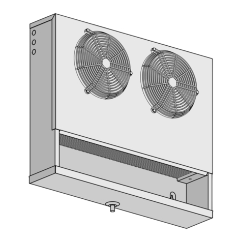
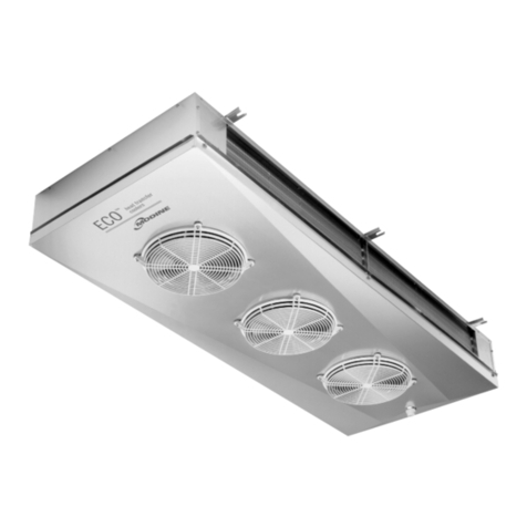
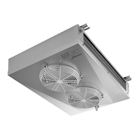
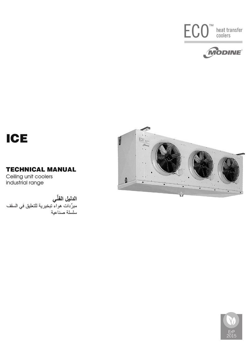
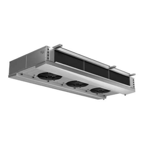
Modine Manufacturing ECO CGC Series User manual

CGC
CO2 COOLERS
TECHNICAL MANUAL
Ceiling unit coolers
BVM03520200221

BVM03520200221

1
www.modine.com
CGC
Indice
- Avvertenze . . . . . . . . . . . . . . . . . . . . . . . . . . . . . . . . . . . . . . . . . . . . . . . . . . . . . . . . . . . . . . . . . . . . . . .2
- Ispezione - Trasporto . . . . . . . . . . . . . . . . . . . . . . . . . . . . . . . . . . . . . . . . . . . . . . . . . . . . . . . . . .2
- Condizioni da verificare per una corretta
messa in opera . . . . . . . . . . . . . . . . . . . . . . . . . . . . . . . . . . . . . . . . . . . . . . . . . . . . . . . . . . . . . . . . . .2
- Manutenzione generale . . . . . . . . . . . . . . . . . . . . . . . . . . . . . . . . . . . . . . . . . . . . . . . . . . . . . .2
- Pericoli . . . . . . . . . . . . . . . . . . . . . . . . . . . . . . . . . . . . . . . . . . . . . . . . . . . . . . . . . . . . . . . . . . . . . . . . . . . . .2
- Norme di riferimento . . . . . . . . . . . . . . . . . . . . . . . . . . . . . . . . . . . . . . . . . . . . . . . . . . . . . . . . . . .2
- Avvertenze per una corretta installazione . . . . . . . . . . . . . . . . . . . . . . . . . . . . . . .3
- Caratteristiche costruttive e dimensionali . . . . . . . . . . . . . . . . . . . . . . . . . . . . . . .3
- Schema di collegamento dei motoventilatori . . . . . . . . . . . . . . . . . . . . . . . . . . .5
- Suggerimenti per un corretto accesso
all’apparecchio . . . . . . . . . . . . . . . . . . . . . . . . . . . . . . . . . . . . . . . . . . . . . . . . . . . . . . . . . . . . . . . . . .6
- Schema di collegamento e potenze delle
resistenze elettriche . . . . . . . . . . . . . . . . . . . . . . . . . . . . . . . . . . . . . . . . . . . . . . . . . . . . . . . . . . .6
- Garanzie . . . . . . . . . . . . . . . . . . . . . . . . . . . . . . . . . . . . . . . . . . . . . . . . . . . . . . . . . . . . . . . . . . . . . . . . .52
Index
- Hinweise . . . . . . . . . . . . . . . . . . . . . . . . . . . . . . . . . . . . . . . . . . . . . . . . . . . . . . . . . . . . . . . . . . . . . . . . .10
- Kontrolle - Transport . . . . . . . . . . . . . . . . . . . . . . . . . . . . . . . . . . . . . . . . . . . . . . . . . . . . . . . . .10
- Hinweise für eine korrekte Inbetriebnahme . . . . . . . . . . . . . . . . . . . . . . . . . . .10
- Allgemeine Wartung . . . . . . . . . . . . . . . . . . . . . . . . . . . . . . . . . . . . . . . . . . . . . . . . . . . . . . . . .10
- Gefahren . . . . . . . . . . . . . . . . . . . . . . . . . . . . . . . . . . . . . . . . . . . . . . . . . . . . . . . . . . . . . . . . . . . . . . . .10
- Bezugsnormen . . . . . . . . . . . . . . . . . . . . . . . . . . . . . . . . . . . . . . . . . . . . . . . . . . . . . . . . . . . . . . . .10
- Hinweise für eine korrekte Aufstellung . . . . . . . . . . . . . . . . . . . . . . . . . . . . . . . . . .11
- Konstruktionseigenschaften und
Abmessungen . . . . . . . . . . . . . . . . . . . . . . . . . . . . . . . . . . . . . . . . . . . . . . . . . . . . . . . . . . . . . . . . . .11
- Anschlußplan der Motorventilatoren . . . . . . . . . . . . . . . . . . . . . . . . . . . . . . . . . . . .13
- Ratschläge für einen korrekten ugang
zum Gerät . . . . . . . . . . . . . . . . . . . . . . . . . . . . . . . . . . . . . . . . . . . . . . . . . . . . . . . . . . . . . . . . . . . . . . .14
- Anschlußplan und Leistungen der
Heizstäbe . . . . . . . . . . . . . . . . . . . . . . . . . . . . . . . . . . . . . . . . . . . . . . . . . . . . . . . . . . . . . . . . . . . . . . .14
- Gewährleistung . . . . . . . . . . . . . . . . . . . . . . . . . . . . . . . . . . . . . . . . . . . . . . . . . . . . . . . . . . . . . . . .52
Index
- Important . . . . . . . . . . . . . . . . . . . . . . . . . . . . . . . . . . . . . . . . . . . . . . . . . . . . . . . . . . . . . . . . . . . . . . . .18
- Inspection - Transport . . . . . . . . . . . . . . . . . . . . . . . . . . . . . . . . . . . . . . . . . . . . . . . . . . . . . . .18
- For a proper installation . . . . . . . . . . . . . . . . . . . . . . . . . . . . . . . . . . . . . . . . . . . . . . . . . . . . .18
- General maintenance . . . . . . . . . . . . . . . . . . . . . . . . . . . . . . . . . . . . . . . . . . . . . . . . . . . . . . .18
- Hazards / Risks . . . . . . . . . . . . . . . . . . . . . . . . . . . . . . . . . . . . . . . . . . . . . . . . . . . . . . . . . . . . . . .18
- Reference standards . . . . . . . . . . . . . . . . . . . . . . . . . . . . . . . . . . . . . . . . . . . . . . . . . . . . . . . .18
- Instructions for a correct installation . . . . . . . . . . . . . . . . . . . . . . . . . . . . . . . . . . . . .19
- Manufacturing and dimensional features . . . . . . . . . . . . . . . . . . . . . . . . . . . . . .19
- Fan motor connection scheme . . . . . . . . . . . . . . . . . . . . . . . . . . . . . . . . . . . . . . . . . . .21
- Recommendations for a proper access to model . . . . . . . . . . . . . . . . . . .22
- Electric heater connection schemes
and electric power . . . . . . . . . . . . . . . . . . . . . . . . . . . . . . . . . . . . . . . . . . . . . . . . . . . . . . . . . . . .22
- Warranty . . . . . . . . . . . . . . . . . . . . . . . . . . . . . . . . . . . . . . . . . . . . . . . . . . . . . . . . . . . . . . . . . . . . . . . . .52
Indice
- Advertencias . . . . . . . . . . . . . . . . . . . . . . . . . . . . . . . . . . . . . . . . . . . . . . . . . . . . . . . . . . . . . . . . . . .26
- Inspección - Transporte . . . . . . . . . . . . . . . . . . . . . . . . . . . . . . . . . . . . . . . . . . . . . . . . . . . . .26
- Condiciones a verificar para una correcta
puesta en marcha . . . . . . . . . . . . . . . . . . . . . . . . . . . . . . . . . . . . . . . . . . . . . . . . . . . . . . . . . . . .26
- Manutención general . . . . . . . . . . . . . . . . . . . . . . . . . . . . . . . . . . . . . . . . . . . . . . . . . . . . . . . .26
- Peligros . . . . . . . . . . . . . . . . . . . . . . . . . . . . . . . . . . . . . . . . . . . . . . . . . . . . . . . . . . . . . . . . . . . . . . . . . .26
- Normas de referencia . . . . . . . . . . . . . . . . . . . . . . . . . . . . . . . . . . . . . . . . . . . . . . . . . . . . . . .26
- Advertencias para una correcta instalación . . . . . . . . . . . . . . . . . . . . . . . . . . .27
- Características constructivas y
dimensionales . . . . . . . . . . . . . . . . . . . . . . . . . . . . . . . . . . . . . . . . . . . . . . . . . . . . . . . . . . . . . . . . .27
- Esquema de conexión motoventiladores . . . . . . . . . . . . . . . . . . . . . . . . . . . . . .29
- Sugerencias para un correcto acceso
al aparato . . . . . . . . . . . . . . . . . . . . . . . . . . . . . . . . . . . . . . . . . . . . . . . . . . . . . . . . . . . . . . . . . . . . . . .30
- Esquema de conexión y potencia
de las resistencias eléctricas . . . . . . . . . . . . . . . . . . . . . . . . . . . . . . . . . . . . . . . . . . . . . .30
- Garantias . . . . . . . . . . . . . . . . . . . . . . . . . . . . . . . . . . . . . . . . . . . . . . . . . . . . . . . . . . . . . . . . . . . . . . . .52
Index
- Attention . . . . . . . . . . . . . . . . . . . . . . . . . . . . . . . . . . . . . . . . . . . . . . . . . . . . . . . . . . . . . . . . . . . . . . . . .34
- Inspection - Transport . . . . . . . . . . . . . . . . . . . . . . . . . . . . . . . . . . . . . . . . . . . . . . . . . . . . . . .34
- Conditions à vérifier pour une
mise en marche correcte . . . . . . . . . . . . . . . . . . . . . . . . . . . . . . . . . . . . . . . . . . . . . . . . . . .34
- Entretien général . . . . . . . . . . . . . . . . . . . . . . . . . . . . . . . . . . . . . . . . . . . . . . . . . . . . . . . . . . . . . .34
- Dangers . . . . . . . . . . . . . . . . . . . . . . . . . . . . . . . . . . . . . . . . . . . . . . . . . . . . . . . . . . . . . . . . . . . . . . . . .34
- Normes de référence . . . . . . . . . . . . . . . . . . . . . . . . . . . . . . . . . . . . . . . . . . . . . . . . . . . . . . . .34
- Instructions pour une installation correcte . . . . . . . . . . . . . . . . . . . . . . . . . . . . .35
- Caractéristiques constructives et
dimensionnelles . . . . . . . . . . . . . . . . . . . . . . . . . . . . . . . . . . . . . . . . . . . . . . . . . . . . . . . . . . . . . . .35
- Schéma de connexion motoventilateurs . . . . . . . . . . . . . . . . . . . . . . . . . . . . . . .37
- Instructions pour accéder à l’appareil . . . . . . . . . . . . . . . . . . . . . . . . . . . . . . . . . . .38
- Schéma de connexion et puissances
des résistances électriques . . . . . . . . . . . . . . . . . . . . . . . . . . . . . . . . . . . . . . . . . . . . . . . .38
- Garantie . . . . . . . . . . . . . . . . . . . . . . . . . . . . . . . . . . . . . . . . . . . . . . . . . . . . . . . . . . . . . . . . . . . . . . . . .52
Содержание
- Меры предосторожности . . . . . . . . . . . . . . . . . . . . . . . . . . . . . . . . . . . . . . . . . . . . . . . . .42
- Осмотр - Транспортировка . . . . . . . . . . . . . . . . . . . . . . . . . . . . . . . . . . . . . . . . . . . . . . .42
- Условия для выполнения корректного
ввода в эксплуатацию . . . . . . . . . . . . . . . . . . . . . . . . . . . . . . . . . . . . . . . . . . . . . . . . . . . . .42
- Общее техобслуживание . . . . . . . . . . . . . . . . . . . . . . . . . . . . . . . . . . . . . . . . . . . . . . . . .42
- Опасность/ Риски . . . . . . . . . . . . . . . . . . . . . . . . . . . . . . . . . . . . . . . . . . . . . . . . . . . . . . . . . . . .42
- Ссылка на стандарты . . . . . . . . . . . . . . . . . . . . . . . . . . . . . . . . . . . . . . . . . . . . . . . . . . . . . .42
- Меры предосторожности
для корректной установки . . . . . . . . . . . . . . . . . . . . . . . . . . . . . . . . . . . . . . . . . . . . . . .43
- Конструктивные
и пространственные характеристики . . . . . . . . . . . . . . . . . . . . . . . . . . . . . . . .43
- Схема подключения мотовентиляторов . . . . . . . . . . . . . . . . . . . . . . . . . . . .45
- Рекомендации по корректному
доступу к аппарату . . . . . . . . . . . . . . . . . . . . . . . . . . . . . . . . . . . . . . . . . . . . . . . . . . . . . . . . . .46
- Схема подключений и мощностей
электрических сопротивлений . . . . . . . . . . . . . . . . . . . . . . . . . . . . . . . . . . . . . . . . .46
- Гарантии . . . . . . . . . . . . . . . . . . . . . . . . . . . . . . . . . . . . . . . . . . . . . . . . . . . . . . . . . . . . . . . . . . . . . . . .52
Index
BVM03520200221

Caution
Before carrying out maintenance on unit, make sure that the electric feed is disconnegced from main power source: the electric parts
may be connegced to an automatic control system.
Important
1. Keep this manual for the lifespan of model.
2. Read technical manual carefully before installation and prior to
any intervention on model.
3. Use model exclusively for the purpose for which it has been
designed; misuse exempts manufacturer from any responsibility.
Inspection - Transport
1. Upon delivery immediately examine condition of model; should
damages be detegced promptly notify forwarder.
2. During transport of model it is necessary to avoid pressure on
packaging and it must be kept in upright position as indicated
on package.
3. Unpack model as close as possible to installation site. When
packaging is removed from model, care must be exercised in
order to avoid damage to parts.
4. n order to avoid injury from the model's sharp edges (e.g. fins)
during installation and positioning of model use of special pro-
tective gloves is recommended.
For a proper installation
1. Verify structural bearing of ceiling in relation to the weight of
the unit.
2. Verify that the unit is installed horizontally.
3. Ensure an adequate free space (approx. 30% of the inner
room volume) to allow a proper intake and exhaust air circu-
lation.
Particular conditions of installation or operation such as low
or beamed rooms, overstorage, obstrugced intake and exhau-
st air circulation and improper ice build-up due to excessive
entry of humidity in room may negatively affect the stated
performance and may cause defects.
tandard models may not be suitable for blast freezer and
chill room application.
4. The models are equipped with axial fan motors, therefore not
suitable for duct ventilation systems and cannot sustain extra
static air pressure drops.
5. Verify that the operating conditions (temperatures and pressu-
res) are in accordance to those of project.
6. Care must be exercised during the connecting phase in order
to avoid possible distortion of the capillary tubes and shifting of
the distributor.
7. n the case of more than one model installed at close range it is
advisable to avoid alternate defrostings.
8. Fit the appropriate siphons on the condensate drain connec-
tions and assess their efficiency in all working temperatures.
9. Avoid installation of the units next to the cold-room doors.
10. Place the end of defrost temperature feeler in the coldest areas
of the coil, i.e. the areas that tend to freeze more (at the end of
the cycle the unit should be completely ice-free).
The position of this device cannot be defined in advance,
because it varies in accordance to the type cold room and type
of installation.
11. Verify that the electrical feed network is in accordance to the
electrical features of model.
12. Ensure that all the electric wiring is in compliance with the stan-
dards in force.
13. The units are predisposed for ground wiring connection.
The unit installer and/or plant operator must ensure the presen-
ce of an efficient earthing connection to protect against indirect
electric contacts.
The electric heating elements eventually used for defrosting
are housed in junction boxes made of thermoplastic material,
with protection rating P 54.
Upon request, models can be supplied with coils, defrosting
units and fan motors different from the standard ones.
14. The protective film is to be removed from model upon comple-
tion of installation.
15. Access to model, for any type of intervention, is reserved to
qualified personnel as per regulations in force.
General Maintenance
1. Periodically inspect fastenings, electrical connections and con-
nections to cooling installation.
2. t is necessary to arrange periodical cleaning of unit in order to
avoid deposits of toxic substances. Use of mild detergent is
recommended; avoid use of solvents, aggressive, abrasive or
ammonia-based agents.
3. When replacing electric heaters take particular care during
installation in order to avoid damage to the vulcanization; cor-
rectly reset wiring and existing fastening systems to avoid pos-
sible movement during operation.
The above-mentioned operations are to be carried out by qua-
lified personnel only.
Hazards / Ris s
1. Electric shock. The model is equipped with fan
motors and electric defrost heaters. The supply
voltage is 400 V AC. t is important to use
electrical safety systems that are in compliance to
the regulations in force.
2. Burns. The surface of the electric defrost heaters
can reach the temperature of 350 ° C.
3. Cuts. The heat exchanger is made with fins with
sharp edges and the casing is made of sheet
metal parts.
4. Parts in motion. The model is equipped with fan
motors fitted with external protection.
5. Crushing. The weight of unit may exceed 500 kg.
Reference standards
- MACH NES D RECT VE 2006/42/EC
- LOW-VOLTAGE D RECT VE 2006/95/EC
- ELECTROMAGNET C COMPAT B L TY D R. 2004/108/EC
- PED D RECT VE 97/23/EC
18 www.modine.com
BVM03520200221

Engli h
19
www.modine.com
22,5
17,5
30
10
==
P1
135
A
B135
100
336
509
431
387
400 min.
P1 P1
407
Manufacturing and dimensional features
Fastening
detail
Model with ø 250 mm fan motor
Instructions for a correct installation
Minimum distance from wall on heater side - Minimum distance from wall on suction side
During the installation phase observe the minimum dimension
A+250 as to allow an adequate space for the removal and fitting of
heaters.
During the installation phase observe the minimun distance of
400 mm as to allow proper functioning of motor.
251 E4R 251 E4 252 G4 252 E4 253 G4 253 E4 254 G4 254 E4
251 E6R 251 E6 252 G6 252 E6 253 G6 253 E6 254 G6 254 E6
251 E8R 251 E8 252 G8 252 E8 253 G8 253 E8 254 G8 254 E8
1x250 1x250 2x250 2x250 3x250 3x250 4x250 4x250
674 774 1224 1224 1674 1674 2124 2124
380 480 930 930 1380 1380 1830 1830
12 12 12 12 12 12 12 12
12 12 12 12 12 12 12 12
1" 1" 1" 1" 1" 1" 1" 1"
14 16 24 26 33 36 42 46
Model CGC
Fan motors n° x Ø mm
Dimensions A
B
Coil connections In tube (mm)
Out tube (mm)
Drain connection Ø (GAS)
Net weight kg
Use thermostatic valve with external pressure equalizer
Positioning of electric heaters
3RR 4RR
4RR (251ExR)
RBA - High power electric
heater in coil.
RBB - Low power electric
heater in coil.
R A - Electric heater on
inner drip tray.
BVM03520200221

20 www.modine.com
468
424
336
561
400 min.
135 135B
A
22,5
17,5
30
10
==
100
P1
P1 P1
407
Fastening
detail
Positioning of electric heaters
RBA - High power electric heater in coil.
RBB - Low power electric heater in coil.
R A - Electric heater on inner drip tray.
RBA2
RSA1
RBA1
RBB1
RSA1
RBA1
RBA2
RBB1
RBB2
RBA1
RBA2
RSA1
RSA1
RBB1
RBB3
RBB2
RBA1
RBA3
RBA2
RBA4
RBB1
35*F4 ED
35*F6 ED
35*F8 ED
35*E4 ED
35*E6 ED
35*E8 ED
35*E4 EDP
35*E6 EDP
35*E8 EDP
35*F4 EDP
35*F6 EDP
35*F8 EDP
35*A4 ED
35*A6 ED
35*A8 ED
35*A4 EDP
35*A6 EDP
35*A8 EDP
400 min.
135 135B
D C
A
544
499
100
382
608
P1P1
453
22,5
17,5
30
10
==
P1
Model CGC 351 E4 351A4 352 E4 352 A4 353 F4 353A4 354 F4 354 A4 355 A4
351 E6 351A6 352 E6 352 A6 353 F6 353A6 354 F6 354 A6 355 A6
351 E8 351A8 352 E8 352 A8 353 F8 353A8 354 F8 354 A8 355 A8
Fan motors n° x Ø 1x350 1x350 2x350 2x350 3x350 3x350 4x350 4x350 5x350
Dimensions A mm 875 875 1425 1425 1975 1975 2525 2525 3075
B mm 580 580 1130 1130 1680 1680 2230 2230 2780
C mm ------1115 1115 1665
D mm ------1115 1115 1115
In tube (mm) 12 12 12 12 12 12 12 16 16
Out tube (mm) 12 12 12 12 (A8 16) 16 16 (A8 22) 16 (F8 22) 22 22
Drain connection Ø (GAS) 1” 1” 1” 1” 1” 1” 1” 1” 1”
Net weight kg 24 29 45 53 64 69 85 92 113
Positioning of electric heaters
Model with ø 350 mm fan motor
Coil connections
Model with ø 315 mm fan motor
RBA - High power electric heater in coil.
RBB - Low power electric heater in coil.
R A - Electric heater on inner drip tray.
Fastening
detail
Manufacturing and dimensional features
311F4 312F4 313F4 314F4
311F6 312F6 313F6 314F6
311F8 312F8 313F8 314F8
1x315 2x315 3x315 4x315
874 1424 1974 2524
580 1130 1680 2230
12 12 12 12
12 12 12 (F8 16) 16 (F8 22)
1" 1" 1" 1"
22 37 52 67
Model CGC
Fan motors n° x Ø mm
Dimensions A
B
Coil connections In tube (mm)
Out tube (mm)
Drain connection Ø (GAS)
Net weight kg
BVM03520200221

Engli h
21
www.modine.com
Fan motor connection scheme
Important
The motors are equipped with inner thermal protection with automatic reconnection.
Before using motor speed control systems verify the compatibility with the motors;
Non compatible systems may damage motors or increase noise level; the manufacturer will not be responsible for model performance
with speed control systems.
L N
Ø 250 mm fan motor connection scheme
Motor No. 2… (eventual) Motor n. 1 Terminal box
fast connection Terminal
box
Motor No. 2…
(eventual)
Motor n. 1
Feed: 230V/1/50-60 Hz
L = brown or grey N = blue = green / yellow
Feed: 230V/1/50-60 Hz
L = brown N = blue = green / yellow
Ø 315 - 350 mm fan motor connection scheme
Motor No. 2… (eventual) Motor n. 1 Terminal box
Motor No. 2…
(eventual)
Motor n. 1
Modell CGC 251 E4R 251 E4 252G4 252 E4 253G4 253 E4 254G4 254 E4 311F4 312F4 313F4 314F4
251 E6R 251 E6 252G6 252 E6 253G6 253 E6 254G6 254 E6 311F6 312F6 313F6 314F6
251 E8R 251 E8 252G8 252 E8 253G8 253 E8 254G8 254 E8 311F8 312F8 313F8 314F8
Fan motors 1 x 250 2 x 250 3 x 250 4 x 250 1 x 315 2 x 315 3 x 315 4 x 315
Frequency Hz 50 60 50 60 50 60 50 60 50 60 50 60 50 60 50 60
Fan motors A 0,68 - 1,36 - 2,04 - 2,72 - 0,52 0,66 1,04 1,32 1,56 1,98 2,08 2,64
absorption W 95 - 190 - 285 - 380 - 110 148 220 296 330 444 440 592
RPM 1300 1550 1300 1550 1300 1550 1300 1550 1350 1490 1350 1490 1350 1490 1350 1490
Modell CGC 351 E4 351A4 352 E4 352 A4 353 F4 353A4 354 F4 354 A4 355 A4
351 E6 351A6 352 E6 352 A6 353 F6 353A6 354 F6 354 A6 355 A6
351 E8 351A8 352 E8 352 A8 353 F8 353A8 354 F8 354 A8 355 A8
Fan motors 1 x 350 2 x 350 3 x 350 4 x 350 5 x 350
Frequency Hz 50 60 50 60 50 60 50 60 50 60
Fan motors A 0,96 1,08 1,92 2,16 2,88 3,24 3,84 4,32 4,80 5,40
absorption W 185 250 370 500 555 750 740 1000 925 1250
RPM 1420 1660 1420 1660 1420 1660 1420 1660 1420 1660
Terminal
box
BVM03520200221

22 www.modine.com
Access
1. Remove drain connection.
2. Verify that drip tray is free from ice build-up before removing it
by unfastening screws “A”.
3. Loosen self-threading screws “B”, without removing completely,
then slip off side panel.
Remounting
1. Reposition the side panel and fasten with screws “B”.
2. Reposition drip tray, ensuring that the side panels are placed
on the inside and fasten with screws “A”.
3. Reconnect the drain connection.
Support
brackets
Side panel
Terminal
box
Drip tray
Drain connection
nner drip
tray
Fan shroud
Recommendations for a proper access to model
Electric heater connection schemes and electric power
Important
Application of adequate thermal control systems on feeder lines is mandatory.
Performance of all electric heaters must be periodically controlled to avoid damage due to ice build-up.
the manufacturer is not liable in any way for defects caused by non detegced malfunctions.
Model CGC “ED” 251E4R 251E4 252G4 252E4 253G4 253E4 254G4 254E4
ø 250 251E6R 251E6 252G6 252E6 253G6 253E6 254G6 254E6
251E8R 251E8 252G8 252E8 253G8 253E8 254G8 254E8
Rows 4 RR 4 RR 3 RR 4 RR 3 RR 4 RR 3 RR 4 RR
Total power (W) 750 1125 2250 2250 3325 3325 4375 4375
RBA (1-2)
High power electric heaters in coil.
RBB1
Low power electric heaters in coil.
R A1
High power electric heater on inner drip tray.
RBB1
RBA1
RSA1
L
N
N
RBB1
RBA1
RSA1
P.E.
N
L
L
RBB1
RBA1
RSA1
L
N
N
RBB1
RBA1
RSA1
P.E.
N
L
L
RBA2
RBA1
RSA1
L
N
N
RBA2
RBA1
RSA1
P.E.
N
L
L
R
S
T
N
RBB1
RSA1
RBA1
R
S
T
N
RBB1
RSA1
RBA1
R
S
T
N
RBA2
RSA1
RBA1
N
RBB1
RBA1
RSA1
P.E.
N
R
U
RBB1
RBA1
RSA1
V
W
S
T
N
P.E.
N
R
U
V
W
S
T
RBA2
RBA1
RSA1
N
P.E.
N
R
U
V
W
S
T
CGC 251ExR CGC 252Gx
253Gx
254Gx
CGC 251Ex
252Ex
253Ex
254Ex
Model with ø 250 mm fan motor
CONNECT ON 400V/3/50 Hz PRE ET
BVM03520200221

Engli h
23
www.modine.com
Electric heater connection schemes and electric power
RSA1
RBA1
RBA2
RBB1
UV
W
N
N
W
PE
V
U
R
S
T
N
R
S
T
N
RBB1
RSA1
RBA2
RBA1
RSA1
RBA1
N
L
N
RBB1
RBA2
RBA1
RSA1
L
N
L
N
W
V
U
RBA2
RBB1
PE
Model CGC “ED” 311F4 321F4 313F4 314F4
ø 315 311F6 321F6 313F6 314F6
311F8 321F8 313F8 314F8
Rows 5 RR 5 RR 5RR 5 RR
Total power (W) 1750 3150 4900 6300
400V/3/50 Hz CONNECT ON 230V/1/50 Hz CONNECT ON
(preset) (to set)
Model with ø 315 mm fan motor
RBA (1-2) High power electric heaters in coil.
RBB1 Low power electric heaters in coil.
R A1 High power electric heater on inner drip tray.
Important
Application of adequate thermal control systems on feeder lines is mandatory.
Performance of all electric heaters must be periodically controlled to avoid damage due to ice build-up.
the manufacturer is not liable in any way for defects caused by non detegced malfunctions.
Model CGC “ED” 251E4R 251E4 252G4 252E4 253G4 253E4 254G4 254E4
ø 250 251E6R 251E6 252G6 252E6 253G6 253E6 254G6 254E6
251E8R 251E8 252G8 252E8 253G8 253E8 254G8 254E8
Rows 4 RR 4 RR 3 RR 4 RR 3 RR 4 RR 3 RR 4 RR
Total power (W) 750 1125 2250 2250 3325 3325 4375 4375
Model with ø 250 mm fan motor
RBB1
RBA1
RSA1
L
N
N
RBB1
RBA1
RSA1
P.E.
N
L
L
RBB1
RBA1
RSA1
L
N
N
RBB1
RBA1
RSA1
P.E.
N
L
L
RBA2
RBA1
RSA1
L
N
N
RBA2
RBA1
RSA1
P.E.
N
L
L
R
S
T
N
RBB1
RSA1
RBA1
R
S
T
N
RBB1
RSA1
RBA1
R
S
T
N
RBA2
RSA1
RBA1
N
RBB1
RBA1
RSA1
P.E.
N
R
U
RBB1
RBA1
RSA1
V
W
S
T
N
P.E.
N
R
U
V
W
S
T
RBA2
RBA1
RSA1
N
P.E.
N
R
U
V
W
S
T
CGC 251ExR CGC 252Gx
253Gx
254Gx
CGC 251Ex
252Ex
253Ex
254Ex
CONNECT ON 230V/1/50 Hz TO ET
RBA (1-2)
High power electric heaters in coil.
RBB1
Low power electric heaters in coil.
R A1
High power electric heater on inner drip tray.
BVM03520200221

24 www.modine.com
RSA1
RBA1
RBA2
RBB1
R
S
T
N
RSA1
RBB1
RBA1
RSA1
RBA1
L
N
RBB2
RBA2
RBB1
RBA1
RSA1
RBB2
RBB2
RBA2
RBA2
RBB1
RBB2
UV
W
N
N
W
PE
V
U
R
S
T
N
N
L
N
L
N
W
V
U
PE
400V/3/50 Hz CONNECT ON 230V/1/50 Hz CONNECT ON
(preset) (to set)
Model with ø 350 mm fan motor 4-5 RR strengthen
RBA (1-2) High power electric heaters in coil.
RBB (1-2) Low power electric heaters in coil.
R A1 High power electric heater on inner drip tray.
Electric heater connection schemes and electric power
Important
Application of adequate thermal control systems on feeder lines is mandatory.
Performance of all electric heaters must be periodically controlled to avoid damage due to ice build-up.
the manufacturer is not liable in any way for defects caused by non detegced malfunctions.
Model CGC “ED” 351 E4 352 E4 353 F4 354 F4
ø 350 351 E6 352 E6 353 F6 354 F6
351 E8 352 E8 353 F8 354 F8
Rows 4 RR 4 RR 5 RR 5 RR
Total power (W) 2000 3600 5600 7200
R
S
N
T
RBB1
RSA1
RBA2
RBA1
L
N
RBB1
RBA2
RBA1
RSA1
RSA1
RBA1
RBA2
RBB1
UV
W
N
N
W
PE
V
U
R
S
T
N
RSA1
RBA1
RBA2
RBB1
N
L
N
L
N
W
V
U
PE
Model CGC “ED” 351 E4 352 E4 353 F4 354 F4
ø 350 351 E6 352 E6 353 F6 354 F6
351 E8 352 E8 353 F8 354 F8
Rows 4 RR 4 RR 5 RR 5 RR
Total power (W) 1750 3150 4900 6300
400V/3/50 Hz CONNECT ON 230V/1/50 Hz CONNECT ON
(preset) (to set)
Model with ø 350 mm fan motor 4-5 RR standard
RBA (1-2) High power electric heaters in coil.
RBB1 Low power electric heaters in coil.
R A1 High power electric heater on inner drip tray.
BVM03520200221

Engli h
25
www.modine.com
Electric heater connection schemes and electric power
Important
Application of adequate thermal control systems on feeder lines is mandatory.
Performance of all electric heaters must be periodically controlled to avoid damage due to ice build-up.
the manufacturer is not liable in any way for defects caused by non detegced malfunctions.
RSA1
RBA1
RBA2
RBA3
RBB1
RBA4
UV
W
N
N
W
V
U
R
S
T
N
RBB1
R
S
T
N
RBA1
RBA4
RSA1
RBA3
RBA2
RSA1
RBA1
RBA2
RBA3
N
L
N
RBB1
RBA4
RBA3
RBA2
RBA1
RSA1
L
N
L
N
W
V
U
RBB1
RBA4
PE PE
400V/3/50 Hz CONNECT ON 230V/1/50 Hz CONNECT ON
(preset) (to set)
RBA (1-2-3-4) High power electric heaters in coil.
RBB1 Low power electric heaters in coil.
R A1 High power electric heater on inner drip tray.
Model with ø 350 mm fan motor 6 RR strengthen
Model CGC “ED” 351 A4 352 A4 353 A4 354 A4 355 A4
ø 350 351 A6 352 A6 353 A6 354 A6 355 A6
351 A8 352 A8 353 A8 354 A8 355 A8
Rows 6 RR 6 RR 6 RR 6 RR 6 RR
Total power (W) 2750 4950 7700 9900 12100
RSA1
RBA1
RBB1
RBA2
RBB3
RBB2
UV
W
N
N
W
V
U
R
S
T
N
RBB3
R
S
T
N
RBB1
RBA2
RSA1
RBB2
RBA1
RSA1
RBA1
RBB1
RBA2
RBB3
RBB2
RSA1
RBA1
RBB1
RBA2
RBB3
RBB2
R
S
T
RBB3
RBB1
RBA2
RSA1
RBB2
RBA1
UV
W
N
W
V
U
R
S
T
N
L
N
RBB3
RBA2
RBB2
RBA1
RBB1
RSA1
L
N
L
N
W
V
U
PE
PE PE
400V/3/50 Hz CONNECT ON 230V/3/50 Hz CONNECT ON 230V/1/50 Hz CONNECT ON
(preset) (to set) (to set)
RBA (1-2) High power electric heater in coil.
RBB (1-2-3) Low power electric heaters in coil.
R A1 High power electric heater on inner drip tray.
Model with ø 350 mm fan motor 6 RR standard
Model CGC “ED” 351 A4 352 A4 353 A4 354 A4 355 A4
ø 350 351 A6 352 A6 353 A6 354 A6 355 A6
351 A8 352 A8 353 A8 354 A8 355 A8
Rows 6 RR 6 RR 6 RR 6 RR 6 RR
Total power (W) 2250 4050 6300 8100 9900
BVM03520200221

BVM03520200221

51
www.modine.com
Garanzie
Tutte le informazioni tecniche presenti in questa edizione sono asate su prove che riteniamo ampie e attendi ili, ma che non possono essere riferite a tutta la casistica dei possi ili impieghi.Pertanto, l’acquirente
deve accertare l’idoneità del prodotto all’uso per il quale intende destinarlo, assumendo ogni responsa ilità derivante dall’utilizzo dello stesso. La società venditrice, su richiesta dell’acquirente, si renderà disponi ile
fornendo tutte le informazioni utili per il migliore utilizzo dei suoi prodotti.Tutti i nostri modelli sono garantiti per due anni dalla data di fatturazione degli stessi; si prega di consultare la sezione “Garanzia” dei
“Termini e Condizioni di Vendita” reperi ili sul nostro sito internet www.luvata.com per un maggior approfondimento. Sono ad ogni modo escluse da ogni forma di garanzia le avarie occasionali quali quelle dovute
al trasposto, le manomissioni da parte di personale non autorizzato, l’utilizzo non corretto e le errate installazioni a cui vengano sottoposti i prodotti.
La costante ricerca svolta dai nostri la oratori per garantire prodotti sempre migliori e innovativi potre e causare la modifica dei dati qui contenuti. Sarà dunque compito dell’utilizzatore mantenersi aggiornato
sulla loro validità.
Nessuna parte di questa pu licazione può essere riprodotta o imitata senza autorizzazione. Decliniamo ogni responsa ilità per eventuali errori di stampa o omissioni e ci riserviamo il diritto di apportare senza
preavviso e in qualsiasi momento le modifiche che riterremo opportune.
Gewährleistung
Alle technischen Informationen in dieser Ausga e asieren auf Tests, die wir für weit gefächert und zuverlässig halten, a er nicht alle möglichen Anwendungen ein eziehen können. Daher muss der Käufer die
Eignung des Produkts für den Zweck, für den es estimmt ist, ü erprüfen, und die gesamte Verantwortung für die Verwendung dersel en ü ernehmen. Der Verkäufer steht auf Anfrage des Käufers zur Verfügung,
alle nützlichen Informationen für die este Anwendung seiner Produkte zu erteilen. Alle unsere Produkte sind für zwei Jahre a dem Rechnungsdatum der Produkte garantiert; für weitere Informationen konsultieren
sie den A schnitt "Garantie" der "Allgemeinen Geschäfts edingungen für den Verkauf" auf unserer We site www.luvata.com. Von jeder Form der Garantie ausgeschlossen sind auf alle Fälle eventuelle
Beschädigungen durch den Transport, Manipulationen durch nicht autorisiertes Personal, nicht korrekter Ge rauch und fehlerhafte Installationen.
Durch die ständige Forschung unserer La ors, um immer essere und innovativere Produkte zu garantieren, kann es zur Änderung der hier einhaltenden Daten kommen, es ist daher Aufga e des Benutzers sich
ü er die Gültigkeit auf dem Laufenden zu halten.
Kein Teil dieser Veröffentlichung darf ohne Genehmigung wiedergege en oder nachgeahmt werden, wir lehnen jede Verantwortung für eventuelle Druck- oder Schrei fehler a und ehalten uns das Recht vor,
jederzeit und ohne vorherige Benachrichtigung Änderungen vorzunehmen, die wir für zweckmäßig halten.
Warranty
All technical information in this edition is ased on tests carried out, which we deem exhaustive and relia le ut which cannot e referred to all records of possi le applications. Therefore, the purchaser must
ascertain product suita ility with regard to its intended use, undertaking all responsi ility arising from its said use. Upon request y the purchaser, the seller shall e availa le to supply all useful information in
order to use his products etter. All our models have a two-year warranty with effect from the date of the said invoice. Please refer to the section regarding “Warranty” under “Purchase Terms and Conditions”,
which can e found on our we site www.luvata.com for more in-depth information. However, occasional failures such as those due to transport, tampering y unauthorised personnel, incorrect use and incorrect
installation, which the products are su jegced to, are all excluded from any form of warranty.
As a result of continuing research and design y our technical la oratories, aimed at offering top quality and innovative products, the information given in this guide may e su ject to modification at any time
without prior notice; it is up to the user to keep up to date on all possi le modifications.
No part of this pu lication may e reproduced or duplicated without prior permission; we decline any responsi ility for possi le mistakes or omissions, and we reserve the right to make amendments deemed
necessary, without prior notice and at any time.
Garantias
Todas las informaciones técnicas presentes en esta edición se asan en prue as que consideramos extensas y fia les, pero que no pueden tomarse como referencia para toda la variedad de posi les aplicaciones.
Por lo tanto, el comprador de e compro ar la compati ilidad del producto con el uso para el que pretende destinarlo, asumiendo toda la responsa ilidad derivada del uso del mismo. El vendedor estará a disposición
del comprador para cualquier información útil que pueda servir para el mejor uso posi le de sus productos. Todos nuestros modelos cuentan con una garantía de dos años desde la fecha de facturación de los
mismos. Para más información, se ruega consultar la sección “Garantía” de los Términos y condiciones de venta disponi les en nuestra página we www.luvata.com. Quedan excluidas de cualquier forma posi le
de garantía las averías fortuitas que puedan sufrir los productos, como las de idas al transporte, a la manipulación por parte de personal no autorizado, a un uso no adecuado y a una instalación incorrecta.
En nuestros la oratorios se tra aja sin interrupción para garantizar la mejora y la inovación de los productos. Esto podría causar la modificación de algunos de los datos de esta guía. Por lo tanto, aconsejamos al
usuario averiguar siempre la actualización y validez de los mismos.
Está prohi ido imitar o reproducir el contenido del presente sin previa autorización. Declinamos cualquier responsa ilidad por errores de impresión o de transcripción y omisiones y nos reservamos el derecho de
aportar en cualquier momento, sin aviso, los cam ios que se estime oportuno.
Garantie
Toutes les informations techniques présentes dans cette édition sont asées sur des essais que nous considérons complets et fia les, mais qui ne peuvent pas se référer à tous les cas possi les d’emploi. C’est
pourquoi, l’acheteur doit vérifier la conformité du produit à l’usage auquel il souhaite le destiner, en se chargeant de toute responsa ilité découlant de l’utilisation de celui-ci. Le vendeur, à la demande de l’acheteur,
restera à disposition en fournissant toutes les informations utiles pour assurer une utilisation optimale de ses produits. Tous nos modèles sont garantis pendant deux ans à compter de la date de facturation de
ceux-ci; veuillez consulter la section “Garantie” des “Termes et Conditions de Vente” disponi les sur notre site internet www.luvata.com pour o tenir plus de détails. Sont quoi qu’il en soit exclues de toute forme
de garantie: les pannes occasionnelles telles que celles dues au transport, les altérations de la part d’un personnel non autorisé, l’utilisation incorreCGC et les mauvaises installations auxquelles les produits sont
soumis.
La recherche constante de nos la oratoires visant à garantir des produits toujours meilleurs et innovants pourrait causer la modification des données contenues ici. Il incom era à l’utilisateur de se tenir informé
sur leur validité.
Aucune partie de cette pu lication ne peut être reproduite ou imitée sans autorisation. Nous déclinons toute responsa ilité pour d’éventuelles erreurs d’impression ou omissions et nous réservons le droit d’apporter
sans préavis et à tout moment les modifications que nous retiendrons opportunes.
гарантия
Вся техническая информация, представленная в настоящем издании, основана на опыте изготовителя, который он считает богатым и исчерпывающим, но который может не отвечать всем
возможным целям применения. Поэтому пользователь должен убедиться, что изделие подходит для предназначенных целей, и принять всю ответственность для эксплуатации прибора.
Компания-продавец, по заявке покупателя предоставляет всю необходимую информацию для улучшения эксплуатации собственных изделий Все наши модели покрываются гарантией сроком
на два года с даты выставления счета-фактуры; рекомендуем обратиться к разделам "Гарантия" и "Условия Продажи", которые можно найти на нашем сайте www.luvata.com для получения более
подробной информации. Гарантией в любом случае не покрывается ремонт, выполненный при повреждениях в результате перевозки, разборках, выполненных неуполномоченным персоналом,
неправильным применением и установке, которым подвергается изделие.
В связи с непрерывными исследованиями и разра отками, нацеленными на совершенствование нашей продукции, информация, представленная в данной пу ликации, в лю ой момент может
ыть изменена ез уведомления. Следить за такими изменениями – задача заказчика.
Никакая часть данной пу ликации не может ыть воспроизведена или скопирована ез предварительно полученного разрешения. Мы не несем ответственности за возможные оши ки и
пропуски и сохраняем право вносить нео ходимые исправления в лю ое время ез уведомления.
BVM03520200221

CGCM1702A02P_M
MN263467
Manufacturer:
Luvata taly S.r.l.
33050 Pocenia - Udine - taly
Via Giulio Locatelli, 22
Tel. +39 0432.772.001
Fax +39 0432.779.594
Luvata Italy S.r.l. is part of Modine Manufacturing Company.
BVM03520200221
This manual suits for next models
63
Table of contents
Other Modine Manufacturing Accessories manuals

Modine Manufacturing
Modine Manufacturing ECO CGL User manual

Modine Manufacturing
Modine Manufacturing ECO CGD User manual

Modine Manufacturing
Modine Manufacturing PD/BD User manual

Modine Manufacturing
Modine Manufacturing CGS 11EH3 User manual

Modine Manufacturing
Modine Manufacturing ECO EVS User manual

Modine Manufacturing
Modine Manufacturing ECO CDC Series User manual

Modine Manufacturing
Modine Manufacturing ECO AP 080 User manual

Modine Manufacturing
Modine Manufacturing ECO ICE Series User manual

Modine Manufacturing
Modine Manufacturing ECO CDD Series User manual

Modine Manufacturing
Modine Manufacturing ECO EGK User manual