Modine Manufacturing PD/BD User manual

For Units being Converted from Natural Gas
to Propane Gas Concurrently
Follow carefully the propane conversion instructions, found
in Bulletin 75-511, using the proper high altitude main burner
orifices called out in this literature (75-535) instead of the
orifices in propane conversion kit.
SELECTION OF THE PROPER KIT
To select the proper high altitude kit you need to know the
specifics of the heater you will be converting, and the altitude
it will be going into. If the high altitude kits are ordered at the
same time as the unit heater, all pertinent information relative to
the heater can be obtained from the catalog. If the high altitude
kit is needed after the unit heater is in the field, you need to
refer to the carton label or unit heater serial plate to obtain the
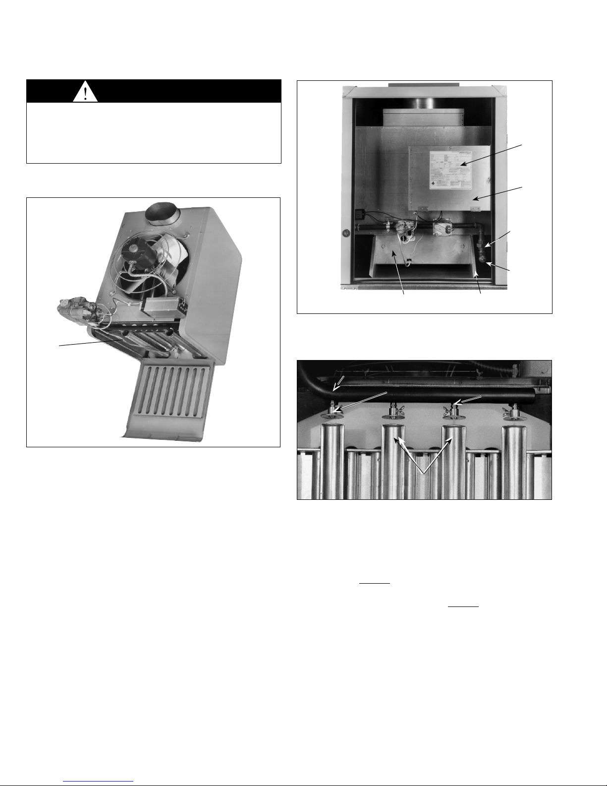
necessary information. Figure 8.2 shows a portion of the unit
heater serial plate where this information may be obtained.
Referring to this figure, the prefix letters and successive
numbers which are needed for kit selection are BV 100. The
letters identify the model and the numbers the size of the unit.
To determine the type of gas the unit is designed for, see the
gas designation disc (Figure 1.1) and the type of gas, located on
the serial plate.
After obtaining this information, refer to the proper selection
chart. The selection charts are differentiated by product type,
altitude and fuel type. Remember, if you are converting from
natural gas to propane gas and want to operate at high altitude,
both a propane conversion kit and a propane high altitude kit
must be used. Selection charts include the proper kit suffix, the
orifice drill size, and the number of orifices required for the unit
being converted. Drill sizes are also stamped on each orifice.
HIGH ALTITUDE CONVERSION
For Existing Natural or Propane Gas Units
Gas-fired equipment ratings are certified by C.S.A. For
elevations above 2000 ft., ANSI Z223.1 requires ratings be
reduced 4 percent for each 1000 ft. above sea level. C.G.A.
requires that ratings be reduced 10% at elevations above 2000
ft. To accommodate higher altitude operation, equipment
must be converted by changing orifices as explained in
this instruction sheet. Tables 2.1 thru 5.2 list orifice kits which
comply with both ANSI Z223.1 recommendations and C.S.A.
requirements.
Table of Contents Pages
High altitude conversion ......................................................... 1
High altitude propane gas
conversion from natural gas ............................................. 1
Selection of the proper kit....................................................... 1
Installation of kits.................................................................... 6
Cross reference...................................................................... 8
THIS MANUAL IS THE PROPERTY OF THE OWNER.
PLEASE BE SURE TO LEAVE IT WITH HIM WHEN YOU LEAVE THE JOB.
SELECTION AND INSTALLATION INSTRUCTIONS
high altitude orifice kit
models PD/BD, PDP/BDP, PSH/BSH
and model series “D”, “H”, “I”, “O” duct furnace/make up air units
(not including separated combustion)
Figure 1.1 - Gas Designation Disc
EQUIPPED
FOR USE
WITH
PROPANE
GAS
NTRL
5H604841A
NRTL
IMPORTANT
Conversion from natural gas to propane gas is allowed for
PD/BD, PDP/BDP, and PSH/BSH models with 11,12, 30,
or 31 control codes, built in January, 1987 or later. For this
conversion, both a propane conversion kit and a propane
high altitude kit must be used.
WARNING
1. All field gas piping must be pressure/leak tested prior to
operation. Never use an open flame. Use a soap solution
or equivalent for testing.
2. Gas supply shall be shut-off and the electrical power
disconnected before proceeding with the conversion.
Failure to do so could result in fire, explosion or electrical
shock.
1. The use of this manual is specifically intended for a
qualified installation and service agency. All installation
and service of these kits must be performed by a qualified
installation and service agency.
2. These instructions must also be used in conjunction with
the Installation and Service manual originally shipped with
the appliance being converted, in addition to any other
accompanying component supplier literature.
IMPORTANT
As Modine Manufacturing Company has a continuous
product improvement program, it reserves the right
to change design and specifications without notice.
75-535.11
5H605846A Rev. Ul
December, 2008

275-535.11
Table 2.1 - Natural Gas - 2001 to 4500 ft. Elevations - PD/BD, PDP/BDP, PSH/BSH, model series “D”, “H”,“I”, & ,“O” ➀➁
Table 2.2 - Natural Gas - 4501 to 5500 ft. Elevations - PD/BD, PDP/BDP, PSH/BSH, model series “D”, “H”,“I”, & ,“O” ➀➁
Model Model Size
Type 30 50 75 100 125 130 150 170 175 200 225 250 280 300 340 350 400
PD/BD, PDP/BDP 30 50 75 100 125 - 150 - 175 200 - 250 -300 -350 400
Kit Suffix -33 -121 -127 -22 -23 - -128 - -15 -26 - -112 - -87 - -129 -126
Drill Size 42 31 25 31 29 - 25 - 30 28 - 22 - 25 - 27 28
Orifices in Kit 1 1 1 2 2 - 2 - 3 3 - 3 - 4 - 5 6
PSH/BSH - - - - - 130 150 170 - - 225 - 280 - 340 - -
Kit Suffix - - - - - 504 508 15 - - 513 - 95 - 522 - -
Drill Size - - - - - 29 31 30 - - 25 - 27 - 28 - -
Orifices in Kit - - - - - 2 3 3 - - 3 - 4 - 5 - -
Pressure
Switch in Kit - - - - - YES YES NO - - YES - NO - YES - -
➂ - - 75 100 125 - 150 - 175 200 225 250 - 300 - 350 400
Kit Suffix - - -120 -22 -14 - -94 - -15 -122 -50 -10 - -92 - -97 -93
Drill Size - - 24 31 28 - 31 - 30 27 24 28 - 24 - 30 27
Orifices in Kit - - 1 2 2 - 3 - 3 3 3 4 - 4 - 6 6
Indoor Duct Furnaces Weatherproof Duct Furnaces
DFG, DBG, DCG, IFG, IBG, ICG HFG, HBG, HCG, HDG, HPG, OFG, OBG, OCG, ODG, OPG
DFP, DBP, DCP, IFP, IBP, ICP HFP, HBP, HCP, HDP, HPP, OFP, OBP, OCP, ODP, OPP
➂
HIGH ALTITUDE ORIFICE KIT SELECTION GUIDE
Model Model Size
Type 30 50 75 100 125 130 150 170 175 200 225 250 280 300 340 350 400
PD/BD, PDP/BDP 30 50 75 100 125 - 150 - 175 200 - 250 -300 -350 400
Kit Suffix -30 -121 -120 -22 -23 - -90 --15 -26 - -125 - -92 - -88 -126
Drill Size 41 31 24 31 29 - 24 -30 28 - 21 - 24 - 26 28
Orifices in Kit 1 1 1 2 2 - 2 - 3 3 - 3 - 4 - 5 6
PSH/BSH - - - - - 130 150 170 - - 225 - 280 - 340 - -
Kit Suffix - - - - - 14 94 15 - - 50 - 44 - 129 - -
Drill Size - - - - - 28 31 30 - - 24 - 26 - 27 - -
Orifices in Kit - - - - - 2 3 3 - - 3 - 4 - 5 - -
Pressure
Switch in Kit - - - - - NO NO NO - - NO - NO - NO - -
➂ - - 75 100 125 - 150 - 175 200 225 250 300 350 400
Kit Suffix - - -3 -22 -14 - -94 - -7 -8 -9 -10 - -11 - -85 -13
Drill Size - - 23 31 28 - 31 - 29 26 23 28 - 23 - 29 26
Orifices in Kit - - 1 2 2 - 3 - 3 3 3 4 - 4 - 6 6
➀All conversion kits have the same base part number 3H33231, only the suffix of the part number changes by model size.
➁Does not include DFS, DBS, DCS, IFS, IBS, ICS.

3
75-535.11
Table 3.1 - Natural Gas - 5501 to 6500 ft. Elevations - PD/BD, PDP/BDP, PSH/BSH, model series “D”, “H”,“I”, & ,“O” ➀➁
Table 3.2 - Natural Gas - 6501 to 7500 ft. Elevations - PD/BD, PDP/BDP, PSH/BSH, model series “D”, “H”,“I”, & ,“O” ➀➁
➀All conversion kits have the same base part number 3H33231, only the suffix of the part number changes by model size.
➁Does not include DFS, DBS, DCS, IFS, IBS, ICS.
➂Indoor Gravity Vented Duct Furnaces Weatherproof Duct Furnaces
DFG, DBG, DCG, IFG, IBG, ICG HFG, HBG, HCG, HDG, HPG, OFG, OBG, OCG, ODG, OPG,HFP, HBP, HCP, HDP, HPP, OFP, OBP, OCP, ODP, OPP
HIGH ALTITUDE ORIFICE KIT SELECTION GUIDE
Model Model Size
Type 30 50 75 100 125 130 150 170 175 200 225 250 280 300 340 350 400
PD/BD 30 50 75 100 125 - 150 - 175 200 - 250 - 300 - 350 400
Kit Suffix -78 -121 -24 -22 -4 - -102 - -15 -7 - -9 - -44 - -96 -85
Drill Size 43 31 26 31 30 - 26 - 30 29 - 23 - 26 - 28 29
Orifices in Kit 1 1 1 2 2 - 2 - 3 3 - 3 - 4 - 5 6
PDP/BDP 30 50 75 100 125 - 150 - 175 200 - 250 - 300 - 350 400
Kit Suffix -78 -121 -501 -22 -4 - -102 - -15 -7 - -9 - -44 - -96 -85
Drill Size 43 31 26 31 30 - 26 - 30 29 - 23 - 26 - 28 29
Orifices in Kit 1 1 1 2 2 - 2 - 3 3 - 3 - 4 - 5 6
Pressure
Switch in Kit NO NO YES NO NO - NO - NO NO - NO - NO - NO NO
PSH/BSH - - - - - 130 150 170 - - 225 - 280 - 340 - -
Kit Suffix - - - - - 504 508 94 - - 514 - 518 - 522 - -
Drill Size - - - - - 29 31 31 - - 26 - 28 - 28 - -
Orifices in Kit - - - - - 2 3 3 - - 3 - 4 - 5 - -
Pressure
Switch in Kit - - - - - YES YES NO - - YES - YES - YES - -
➂ - - 75 100 125 - 150 - 175 200 225 250 - 300 - 350 400
Kit Suffix - - -127 -22 -23 - -94 - -15 -26 -56 -115 - -87 - -97 -126
Drill Size - - 25 31 29 - 31 - 30 28 25 29 - 25 - 30 28
Orifices in Kit - - 1 2 2 - 3 - 3 3 3 4 - 4 - 6 6
➃ - - 75 100 125 - 150 - 175 200 225 250 - 300 - 350 400
Kit Suffix - - -127 -22 -23 - -94 - -15 -26 -56 -115 - -87 - -97 -526➄
Drill Size - - 25 31 29 - 31 - 30 28 25 29 - 25 - 30 28
Orifices in Kit - - 1 2 2 - 3 - 3 3 3 4 - 4 - 6 6
Model Model Size
Type 30 50 75 100 125 130 150 170 175 200 225 250 280 300 340 350 400
PD/BD 30 50 75 100 125 - 150 - 175 200 - 250 - 300 - 350 400
Kit Suffix -78 -101 -83 -28 -4 - -5 - -94 -7 - -50 - -95 - -100 -85
Drill Size 43 32 27 32 30 - 27 - 31 29 - 24 - 27 - 29 29
Orifices in Kit 1 1 1 2 2 - 2 - 3 3 - 3 - 4 - 5 6
PDP/BDP 30 50 75 100 125 - 150 - 175 200 - 250 - 300 - 350 400
Kit Suffix -78 -101 -502 -28 -4 - -5 - -94 -7 - -50 - -95 - -100 -85
Drill Size 43 32 27 32 30 - 27 - 31 29 - 24 - 27 - 29 29
Orifices in Kit 1 1 1 2 2 - 2 - 3 3 - 3 - 4 - 5 6
Pressure
Switch in Kit NO NO YES NO NO - NO - NO NO - NO - NO - NO NO
PSH/BSH - - - - - 130 150 170 - - 225 - 280 - 340 - -
Kit Suffix - - - - - 505 509 508 - - 515 - 519 - 523 - -
Drill Size - - - - - 30 32 31 - - 27 - 29 - 29 - -
Orifices in Kit - - - - - 2 3 3 - - 3 - 4 - 5 - -
Pressure
Switch in Kit - - - - - YES YES YES - - YES - YES - YES - -
➂ - - 75 100 125 - 150 - 175 200 225 250 - 300 - 350 400
Kit Suffix - - -24 -22 -4 - -94 -15 -7 -8 -91 -44 -97 -85
Drill Size - - 26 31 30 - 31 30 29 26 30 26 30 29
Orifices in Kit - - 1 2 2 - 3 3 3 3 4 4 6 6
➃ - - 75 100 125 - 150 - 175 200 225 250 - 300 - 350 400
Kit Suffix - - -24 -22 -4 - -94 -15 -7 -8 -91 -44 -97 -527➄
Drill Size - - 26 31 30 - 31 30 29 26 30 26 30 29
Orifices in Kit - - 1 2 2 - 3 3 3 3 4 4 6 6
➃Indoor Power Vented Duct Furnaces
DFP, DBP, DCP, IFP, IBP, ICP
➄Kit for DFP, DBP, DCP, IFP, IBP, ICP, 400 size only, also includes
a pressure switch.

475-535.11
Table 4.1 - Propane Gas - 2001 to 4500 ft. Elevations - PD/BD, PDP/BDP, PSH/BSH, model series “D”,“H”,“I”, & ,“O” ➀➁
Table 4.2 - Propane Gas - 4501 to 5500 ft. Elevations - PD/BD, PDP/BDP, PSH/BSH, model series “D”,“H”,“I”, & ,“O” ➀➁
Model Model Size
Type 30 50 75 100 125 130 150 170 175 200 225 250 280 300 340 350 400
PD/BD, PDP/BDP
30 50 75 100 125 - 150 175 - 200 - 250 - 300 - 350 400
Kit Suffix -31 -32 -33 -45 -46 - -108 -63 - -79 - -64 - -49 - -42 -86
Drill Size 54 48 42 48 45 - 42 45 - 44 - 40 - 42 - 43 44
Orifices in Kit 1 1 1 2 2 - 2 3 - 3 - 3 - 4 - 5 6
PSH/BSH - - - - - 130 150 170 - - 225 - 280 - 340 - -
Kit Suffix - - - - - 506 510 109 - - 516 - 40 - 524 - -
Drill Size - - - - - 44 48 46 - - 27 - 43 - 43 - -
Orifices in Kit - - - - - 2 3 3 - - 3 - 4 - 5 - -
Pressure
Switch in Kit - - - - - YES YES NO - - YES - NO - YES - -
➂ - - 75 100 125 - 150 - 175 200 225 250 - 300 - 350 400
Kit Suffix - - -30 -34 -35 - -37 - -63 -38 -48 -72 - -111 - -74 -51
Drill Size - - 41 47 44 - 47 - 45 43 41 44 - 41 - 45 43
Orifices in Kit - - 1 2 2 - 3 - 3 3 3 4 - 4 - 6 6
➂
Model Model Size
Type 30 50 75 100 125 130 150 170 175 200 225 250 280 300 340 350 400
PD/BD, PDP/BDP
30 50 75 100 125 - 150 - 175 200 - 250 - 300 - 350 400
Kit Suffix -52 -32 -33 -45 -35 - -108 --63 -38 - -82 - -49 - -42 -51
Drill Size 53 48 42 48 44 - 42 -45 43 - 39 - 42 - 43 43
Orifices in Kit 1 1 1 2 2 - 2 -3 3 - 3 - 4 - 5 6
PSH/BSH - - - - - 130 150 170 - - 225 - 280 - 340 - -
Kit Suffix - - - - - 77 47 63 - - 39 - 40 - 42 - -
Drill Size - - - - - 43 48 45 - - 42 - 43 - 43 - -
Orifices in Kit - - - - - 2 3 3 - - 3 - 4 - 5 - -
Pressure
Switch in Kit - - - - - NO NO NO - - NO - NO - NO - -
➂ - - 75 100 125 - 150 - 175 200 225 250 - 300 - 350 400
Kit Suffix - - -1 -34 -77 - -37 --79 -38 -64 -40 - -41 - -86 -51
Drill Size - - 40 47 43 - 47 -44 43 40 43 - 40 - 44 43
Orifices in Kit - - 1 2 2 - 3 -3 3 3 4 - 4 - 6 6
HIGH ALTITUDE ORIFICE KIT SELECTION GUIDE
➀All conversion kits have the same base part number 3H33231, only the suffix of the part number changes by model size.
➁Does not include DFS, DBS, DCS, IFS, IBS, ICS.
Indoor Duct Furnaces Weatherproof Duct Furnaces
DFG, DBG, DCG, IFG, IBG, ICG HFG, HBG, HCG, HDG, HPG, OFG, OBG, OCG, ODG, OPG
DFP, DBP, DCP, IFP, IBP, ICP HFP, HBP, HCP, HDP, HPP, OFP, OBP, OCP, ODP, OPP

5
75-535.11
Model Model Size
Type 30 50 75 100 125 130 150 170 175 200 225 250 280 300 340 350 400
PD/BD 30 50 75 100 125 - 150 - 175 200 - 250 - 300 - 350 400
Kit Suffix -31 -106 -78 -59 -46 - -77 - -109 -79 - -48 - -40 - -42 -86
Drill Size 54 49 43 49 45 - 43 - 46 44 - 41 - 43 - 43 44
Orifices in Kit 1 1 1 2 2 - 2 - 3 3 - 3 - 4 - 5 6
PDP/BDP 30 50 75 100 125 - 150 - 175 200 - 250 - 300 - 350 400
Kit Suffix -31 -106 -503 -59 -46 - -77 - -109 -79 - -48 - -40 - -42 -86
Drill Size 54 49 43 49 45 - 43 - 46 44 - 41 - 43 - 43 44
Orifices in Kit 1 1 1 2 2 - 2 - 3 3 - 3 - 4 - 5 6
Pressure
Switch in Kit NO NO YES NO NO - NO - NO NO - NO - NO - NO NO
PSH/BSH - - - - - 130 150 170 - - 225 - 280 - 340 - -
Kit Suffix - - - - - 506 511 37 - - 517 - 520 - 525 - -
Drill Size - - - - - 44 49 47 - - 43 - 43 - 44 - -
Orifices in Kit - - - - - 2 3 3 - - 3 - 4 - 5 - -
Pressure
Switch in Kit - - - - - YES YES NO - - YES - YES - YES - -
➂ - - 75 100 125 - 150 - 175 200 225 250 - 300 - 350 400
Kit Suffix - - -33 -45 -35 - -47 - -63 -38 -39 -72 - -49 - -74 -51
Drill Size - - 42 48 44 - 48 - 45 43 42 44 - 42 - 45 43
Orifices in Kit - - 1 2 2 - 3 - 3 3 3 4 - 4 - 6 6
➃ - - 75 100 125 - 150 - 175 200 225 250 - 300 - 350 400
Kit Suffix - - -33 -45 -35 - -47 - -63 -38 -39 -72 - -49 - -74 -528➄
Drill Size - - 42 48 44 - 48 - 45 43 42 44 - 42 - 45 43
Orifices in Kit - - 1 2 2 - 3 - 3 3 3 4 - 4 - 6 6
Table 5.1 - Propane Gas - 5501 to 6500 ft. Elevations - PD/BD, PDP/BDP, PSH/BSH, model series “D”,“H”,“I”, & ,“O” ➀➁
Table 5.2 - Propane Gas - 6501 to 7500 ft. elevations - PD/BD, PSH/BSH, model series “D”, “H”,“I”, & ,“O” ➀➁
Model Model Size
Type 30 50 75 100 125 130 150 170 175 200 225 250 280 300 340 350 400
PD/BD 30 50 75 100 125 - 150 - 175 200 - 250 - 300 - 350 400
Kit Suffix -31 -106 -78 -59 -46 - -77 - -37 -63 - -39 - -40 - -99 -74
Drill Size 54 49 43 49 45 - 43 - 47 45 - 42 - 43 - 44 45
Orifices in Kit 1 1 1 2 2 - 2 - 3 3 - 3 - 4 - 5 6
PDP/BDP 30 50 75 100 125 - 150 - 175 200 - 250 - 300 - 350 400
Kit Suffix -31 -106 -503 -59 -46 - -77 - -37 -63 - -39 - -40 - -99 -74
Drill Size 54 49 43 49 45 - 43 - 47 45 - 42 - 43 - 44 45
Orifices in Kit 1 1 1 2 2 - 2 - 3 3 - 3 - 4 - 5 6
Pressure
Switch in Kit NO NO YES NO NO - NO - NO NO - NO - NO - NO NO
PSH/BSH - - - - - 130 150 170 - - 225 - 280 - 340 - -
Kit Suffix - - - - - 507 511 512 - - 517 - 521 - 525 - -
Drill Size - - - - - 45 49 47 - - 43 - 44 - 44 - -
Orifices in Kit - - - - - 2 3 3 - - 3 - 4 - 5 - -
Pressure
Switch in Kit - - - - - YES YES YES - - YES - YES - YES - -
➂ - - 75 100 125 - 150 - 175 200 225 250 - 300 - 350 400
Kit Suffix - - -33 -45 -46 - -47 - -63 -79 -39 -119 - -49 - -74 -86
Drill Size - - 42 48 45 - 48 - 45 44 42 45 - 42 - 45 44
Orifices in Kit - - 1 2 2 - 3 - 3 3 3 4 - 4 - 6 6
➃ - - 75 100 125 - 150 - 175 200 225 250 - 300 - 350 400
Kit Suffix - - -33 -45 -46 - -47 - -63 -79 -39 -119 - -49 - -74 -529➄
Drill Size - - 42 48 45 - 48 - 45 44 42 45 - 42 - 45 44
Orifices in Kit - - 1 2 2 - 3 - 3 3 3 4 - 4 - 6 6
HIGH ALTITUDE ORIFICE KIT SELECTION GUIDE
➀All conversion kits have the same base part number 3H33231, only the suffix of the part number changes by model size.
➁Does not include DFS, DBS, DCS, IFS, IBS, ICS.
➂Indoor Gravity Vented Duct Furnaces Weatherproof Duct Furnaces
DFG, DBG, DCG, IFG, IBG, ICG HFG, HBG, HCG, HDG, HPG, OFG, OBG, OCG, ODG, OPG,HFP, HBP, HCP, HDP, HPP, OFP, OBP, OCP, ODP, OPP
➃Indoor Power Vented Duct Furnaces
DFP, DBP, DCP, IFP, IBP, ICP
➄Kit for DFP, DBP, DCP, IFP, IBP, ICP, 400 size only, also includes
a pressure switch.

675-535.11
Conversion of any unit is the responsibility of,
and the risk of the person making the conversion.
INSTALLATION
Step 1 Turn off all electricity and gas to unit.
PD/BD, PDP/BDP, PV/BV Models
Lower bottom pan to expose burner and manifold
(see Figure 6.1).
“D”, “H”, “I”, & “O” Models (not including
separated combustion)
Remove weatherproof duct furnace section access
door to obtain access to the manifold assembly (not
applicable on indoor gravity vented models). See
Figure 6.2.
Disconnect gas manifold at the ground joint union (field
supplied ground joint union on DFG and IFG models
equipped with standard control box). Remove the two
screws holding the manifold to the heat exchanger
support. Slide the manifold through the manifold
bracket.
Figure 6.1 - Hinged Bottom for Burner Service
Figure 6.2 - Manifold Assembly Removal
(HFG model shown for reference)
➀
BURNER SIDE
ACCESS PANEL HEAT EXCHANGER
SUPPORT
MANIFOLD
GROUND
UNION
JOINT
ELECTRICAL
JUNCTION
BOX
SERIAL
PLATE
Figure 6.3 - Burner Orifices and Air Shutters
MANIFOLD AIR
SHUTTER
MIXER
TUBES
MAIN
BURNER
ORIFICE
Step 2 Exchange main burner orifice(s) and install air shutters
if provided (see Figure 6.3). Check the orifice number
stamped on each orifice. Be sure that this number is the
same number indicated on the kit parts list for the kit
being installed (see previous tables).
FOR ALL “D”, “H”, “I”, & “O” UNITS, PROCEED
WITH STEP 3.
IF UNIT BEING CONVERTED IS A PD/BD, PDP/BDP,
PSH/BSH PROCEED WITH STEP 4.
Step 3 “D”, “H”, “I”, & “O” Models
Re-install the manifold assembly making certain that it
is correctly positioned.
Step 4 If a new pressure switch is supplied with your kit,
remove the old pressure switch and install the new
one in it's place. Reconnect the pressure line to the
new switch.
WARNING
1. Disconnect power and gas supply before making
conversion.
2. All field gas piping must be pressure/leak tested prior to
operation. Never use an open flame. Use a soap solution or
equivalent for testing.

7
75-535.11
Figure 7.1 - PDP High Efficiency II Unit Heater
Figure 7.3 - High Altitude Conversion Label
Figure 7.2 - Lifting Flame
Step 5 On the High Altitude Conversion Label (see Figure
7.3) write the drill size, as stamped on orifice, with a
permanent marker. Be sure to check correct orifice size
using the selection instructions beginning on
page 1.
Affix the High Altitude Conversion Label (Figure 7.3)
adjacent to the units serial plate.
Step 6 Restore fuel supply to the unit.
Step 7 Check gas supply pressure at unit upstream from
combination gas control. The supply pressure should
be 6" - 7" W.C. on natural gas or 11" - 14" W. C. on
propane gas.
Step 8 Connect the manometer (or gauge) to the outlet
pressure tap on the combination gas control.
Step 9 Restore electric supply to unit.
Step 10 Follow lighting instructions on unit. Turn up thermostat
setting to call for heat. After the main burners light,
measure the outlet (manifold) pressure of the
combination gas control. The pressure should be 3.5
in. W.C. for natural gas and 10 in. W.C. for propane
gas. The outlet pressure can be adjusted at the
control’s regulator. Turning the adjustment clockwise
will increase the outlet pressure while turning it
counterclockwise will decrease the pressure.
NOTICE
THIS APPLIANCE EQUIPPED FOR HIGH ALTITUDE.
IN U.S. ACCORDING TO ANSI Z223.1
IN CANADA, ACCORDING TO C.G.A. CERTIFICATION
MAIN BURNER ORIFICES CHANGED TO
PLACE THIS LABEL ADJACENT TO SERIAL PLATE. 5H70857A
DRILL
SIZE.
INSTALLATION
Step 11 Check for leaks at all joints and connections in the
gas lines. This is most easily done with a soap/water
solution. Simply brush or spray some of the solution
on a joint or connection and look for bubble formation.
Step 12 Observe the main burner flame. The flame should
have a well-defined conical shape with the base
anchored to the burner port. If the flame appears to be
lifting or rising above the burner port (see Figure 7.2),
loosen the thumb screw on the air shutter and slide
the shutter forward toward the mixer tube (Figure 6.3).
If a majority of the flame is yellow, move the air shutter
back away from the mixer tube. Slight yellow tips on a
propane flame are common and are not objectionable.
For more specific flame control adjustment
instructions, see the Installation and Service Manual
which came with your unit.
Conversion of the unit is complete.

75-535.11
Table 8.1 - High Altitude Kit Cross Reference (3H # to Item Code)
CROSS REFERENCE
Figure 8.2 - Typical Serial Plate
UNIT HEATER FOR INDUSTRIAL / COMMERCIAL USE
AEROTHERME POUR USAGE INDUSTRIEL / COMMERCIAL
MODEL NUMBER
NUMERO DE MODELE
0 TO 2000 FT.
0 ET 610 M.
(IN CANADA)
2000 TO 4500 FT.
610 ET 1370 M.
MINIMUM CLEARANCE TO COMBUSTIBLE MATERIAL
DÉGAGEMENT MINIMUM POUR
MATIÉRES COMBUSTIBLES
INPUT BTU/HR
DEBIT CALORIFIQUE
BTU/HEURE
TYPE OF GAS
TYPE DE GAZ
OUTPUT BTU/HR
RENDEMENT
BTU/HEURE
ORIFICE SIZE
DIM. DE L’ INJECTEUR
Made in U.S.A.
SERIAL NUMBER
NUMERO DE SERIE
VOLTS AMPS PHASE HERTZ
TOP
HAUT IN.
PO.
BOTTOM
BAS IN.
PO.
LEFT SIDE
CÔTÉ GAUCHE IN.
PO.
VENT CONNECTOR
CONNECTEUR
D' AÉRATION IN.
PO.
RIGHT SIDE
CÔTÉ DROIT IN.
PO.
MIN. INLET PRESS. FOR PURPOSE
OF INPUT ADJUSTMENT
PRESSION D’ ALIMENTATION
EN GAZ MIN. ADMISE
IN. W.C.
PO.C.D’ E
MANIFOLD PRESSURE
PRESSION A LA TUBULURE
D’ ALIMENTATION IN. W.C.
PO.C.D’ E
MAXIMUM EXTERNAL
STATIC PRESSURE
PRESSION STATIQUE
EXTERIEUR MAXIMUM
IN. W.C.
PO.C.D’ E
CATEGORY
CATÉGORIE DESIGN COMPLIES WITH UNIT HEATER STANDARD:
APPROVALS
ACCEPTED BY
CITY OF NEW YORK:
PENNSYLVANIA
APPROVAL NO. 3465
APPROVED FOR USE IN
CA BY THE CEC WHEN
EQUIPPED WITH IPI
APPROVED FOR USE
IN MASSACHUSETTS
MIN. INPUT BTU/HR
DEBIT CALORIFIQUE
MIN. BTU/HEURE
SERIES UNIT HEATER IS FOR USE WITH
DUCTS AT A TEMPERATURE RISE RANGE
SERIE AEOTHERME FONCTIONNE AVECS DES
CONDUITS A UNE ELEVATION DE TEMPERATURE DE
F TO
AF
Modine Manufacturing Company
1221 Magnolia Ave., Buena Vista, VA 24416; Phone: 800-828-4328
BDP 100SE0130
15101010203-0022
Natural
100000
80000
30
90000
72000
31
6
12
18
6
6
BV
6
3.5
0.5
115 0.25 1 60
IANS Z83.8b - 1992
CAN/CGA-2.6-M86
MEA 317-88-E
40 70
MODEL
POWER
CODE CONTROL
CODE
Commercial Products Group • Modine Manufacturing Company • 1500 DeKoven Avenue • Racine, Wisconsin 53403-2552
"I" & "O" Model Series - Phone: 1.866.823.1631 (Toll Free) • Fax: 1.800.204.6011
All Other Model Series - Phone: 1.800.828.4328 (HEAT) • Fax: 1.800.204.6011
© Modine Manufacturing Company 2008 Litho in USA
3H# FP#
Item Code 3H# FP#
Item Code 3H# FP#
Item Code 3H# FP#
Item Code 3H# FP#
Item Code
3H33231-1 91684 3H33231-38 91707 3H33231-68 33687 3H33231-97 91734 3H33231-505 49815
3H33231-3 91686 3H33231-39 91708 3H33231-69 29042 3H33231-98 91735 3H33231-506 49816
3H33231-4 91687 3H33231-40 91709 3H33231-70 91720 3H33231-99 91736 3H33231-507 49817
3H33231-5 91688 3H33231-41 91710 3H33231-71 33688 3H33231-100 91737 3H33231-508 49818
3H33231-7 91690 3H33231-42 91711 3H33231-72 91721 3H33231-101 93919 3H33231-509 49819
3H33231-8 91691 3H33231-43 91712 3H33231-73 91722 3H33231-102 93920 3H33231-510 49820
3H33231-9 91692 3H33231-44 28541 3H33231-74 91723 3H33231-106 93924 3H33231-511 49821
3H33231-10 91693 3H33231-45 93930 3H33231-75 33689 3H33231-108 93939 3H33231-512 49822
3H33231-11 91694 3H33231-46 91713 3H33231-76 33690 3H33231-109 93940 3H33231-513 49823
3H33231-12 91695 3H33231-47 97324 3H33231-77 91724 3H33231-111 93942 3H33231-514 49824
3H33231-13 91696 3H33231-48 29033 3H33231-78 91725 3H33231-112 93988 3H33231-515 49825
3H33231-14 91697 3H33231-49 27980 3H33231-79 91726 3H33231-115 93991 3H33231-516 49826
3H33231-15 91698 3H33231-50 29034 3H33231-80 91727 3H33231-119 27987 3H33231-517 49827
3H33231-17 28537 3H33231-51 93931 3H33231-82 27982 3H33231-120 27988 3H33231-518 49828
3H33231-22 91700 3H33231-52 91714 3H33231-83 91728 3H33231-121 27989 3H33231-519 49829
3H33231-23 91701 3H33231-53 29035 3H33231-84 27983 3H33231-122 27990 3H33231-520 49830
3H33231-24 28538 3H33231-54 33686 3H33231-85 91729 3H33231-123 33691 3H33231-521 49831
3H33231-25 28539 3H33231-55 29036 3H33231-86 91730 3H33231-125 27991 3H33231-522 49832
3H33231-26 91702 3H33231-56 29037 3H33231-87 27984 3H33231-126 27992 3H33231-523 49833
3H33231-28 28540 3H33231-59 93932 3H33231-88 27985 3H33231-127 27993 3H33231-524 49834
3H33231-30 91703 3H33231-61 29038 3H33231-90 27986 3H33231-128 27994 3H33231-525 49835
3H33231-31 27977 3H33231-62 29039 3H33231-91 91731 3H33231-129 27996 3H33231-526 56900
3H33231-32 27978 3H33231-63 27981 3H33231-92 93957 3H33231-130 29043 3H33231-527 56901
3H33231-33 93986 3H33231-64 91718 3H33231-93 93852 3H33231-131 29044 3H33231-528 56902
3H33231-34 91704 3H33231-65 29040 3H33231-94 91732 3H33231-132 29045 3H33231-529 56903
3H33231-35 27979 3H33231-66 91719 3H33231-95 93987 3H33231-133 29046
3H33231-37 91706 3H33231-67 29041 3H33231-96 91733 3H33231-504 49814
This manual suits for next models
2
Table of contents
Other Modine Manufacturing Accessories manuals

Modine Manufacturing
Modine Manufacturing ECO AP 080 User manual

Modine Manufacturing
Modine Manufacturing ECO EGK User manual

Modine Manufacturing
Modine Manufacturing ECO EVS User manual

Modine Manufacturing
Modine Manufacturing ECO CGL User manual

Modine Manufacturing
Modine Manufacturing ECO CGD User manual

Modine Manufacturing
Modine Manufacturing ECO CGC Series User manual

Modine Manufacturing
Modine Manufacturing ECO ICE Series User manual

Modine Manufacturing
Modine Manufacturing ECO CDC Series User manual

Modine Manufacturing
Modine Manufacturing ECO User manual

Modine Manufacturing
Modine Manufacturing ECO CDD Series User manual