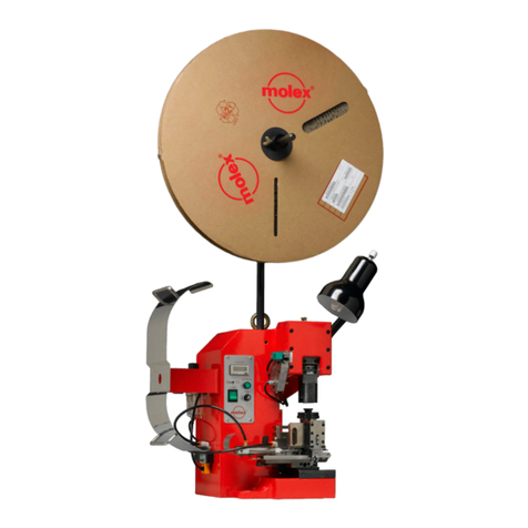
molex TM42 User manual

Molex Terminator
Use In TM42, TM40, Base Unit Adapter
Description • Operation • Maintenance
DOCNo638500090
ReleaseDate99/07/01
RevisionA
RevisionDate99/07/01

3
WARNING
NEVER USE THIS TERMINATOR IN A PRESS WITHOUT GUARDS OR SAFETY DEVICES THAT
ARE INTENDED TO PREVENT INJURY. THE TERMINATOR IS SUPPLIED WITHOUT
GUARDS. PLEASE USE GUARDS SUPPLIED WITH THE PRESS. RUNNING THE PRESS
WITHOUT GUARDS UNDER ANY CIRCUMSTANCES CAN CAUSE SERIOUS INJURY.
NEVER INSTALL, OPERATE ADJUST, OR SERVICE THIS TERMINATOR WITHOUT PROPER IN-
STRUCTION AND WITHOUT FIRST READING AND UNDERSTANDING THE INSTRUC-
TIONS IN THIS MANUAL AND THE TM42 PRESS, TM40 PRESS, OR 3BF WITH BASE
UNIT ADAPTER MANUALS.
NEVER INSTALL,REMOVEORSERVICETERMINATOR TOOLING WHILETHE FLYWHEEL ISIN
MOTION OR POWER CONNECTED TO THE PRESS.
NEVER INSTALL, REMOVE OR SERVICE THE TERMINATOR TOOLING WITHOUT MANUALLY
CYCLING THE PRESS TO VERIFY THAT THE CLUTCH CONTROL IS IN THE LOCKED PO-
SITION PAST TOP DEAD CENTER, BLOCK THE RAM IN THE UP POSITION IF A DEFEC-
TIVE CLUTCH IS SUSPECTED.
CAUTION THE PRESS SHOULD ALWAYS BE HAND CYCLED WITH THE TERMINATOR INSTALLED
PRIOR TO RUNNING PRODUCTION. THIS PROCEDURE WILL PREVENT DAMAGE OR
REDUCE TOOL WEAR.
WORK SAFELY AT ALL TIMES
FOR SERVICE
CONTACT YOUR LOCAL SALES OFFICE
APPLICATION TOOLING GROUP
1150 DIEHL ROAD,
NAPERVILLE, ILLINOIS 60563
PH: (630) 969-4550
FAX: (630) 505-0049

5
Molex Terminator
Table of Contents
Section
1. GeneralDescription
2. Installation-Setup-Operation
3. Maintenance
Appendix
A. TerminatorTypes&T2AssemblyDrawing
B. CrimpDefinitions
C. StatisticalProcessControl(Summary)

7
SECTION 1
General Description
Page
1.1 Description................................................................... 9
1.2 Features .................................................................... 9
1.3 TechnicalSpecifications.......................................................... 9
1.4 DeliveryCheck............................................................... 10
1.5 Tools .......................................................................10
1.6 Safety &Work Area Check . .. . .. . .. . . .. . .. . .. . . .. . .. . .. . . .. . .. . .. . . .. . .. . .. . .. . . .10

8
Molex Presses and Adapters
For “T” or “T2” Style Terminators
TM42 Press
■
ISOMetric.
■
Flexibleexternallight.
■
Resettablecounter.
■
1.5”Stroke.
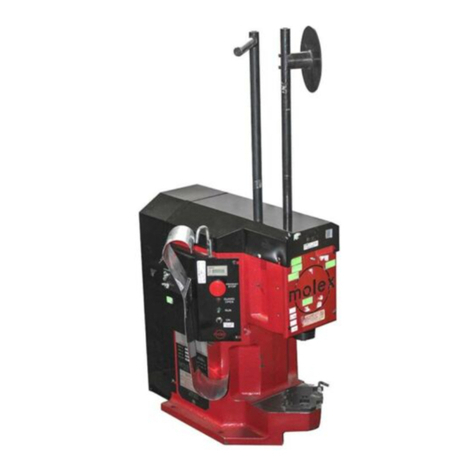
TM40 Press
■
InternalLight.
■
Nonresettablecounter.
■
1.0”Stroke.
Base Unit Adapter
■
Allows3BFpresstorunTerminatorstyletooling.

9
General Description
1.1 Description
TheMolexTerminatorisaneasytousetoolfortheterminationofavarietyofMolexcrimpterminals.
Productionflexibilityisobtainedthroughtheuseofsimpleinterchangeabletooling. Thetoolingis
inexpensive,andunlikeamodularapplicator,allcrimpheightandterminalfeedadjustmentsarelocated
inthepress. TheterminatordiecanbeinstalledintheTM42,TM40pressesorBaseUnitadaptor,andis
ideallysuitedformid-volumebenchoperation.
TheMolexT2terminatoristhenewerversiontoolthatallowsfortrackadjustment. Itcontainstheidentical
perishabletoolingastheMolexFineAdjustapplicator. (Centercarrierexcluded)
1.2 Features
■
Flexibleandinexpensive.
■
Enhancedcrimpingproductivity.
■
Simpleinstallation.
■
Quickreleasepunches.
■
T2terminatorhasstandardizedtoolingwithMolexFineAdjustApplicator.
■
TrackAdjustmentcapabilitiesintheT2terminatorsforimprovedcontrolofthebellmouthsizeandcutoff
tablength.
1.3 Technical Specifications
Dimensions
Width- 127.0mm(5.0”)
Depth- 44.0mm(1.8”)
Height- 25.0mm(1”)
Weight- 1.4kg(3.0lbs)

10
1.4 Delivery Check
Qty
Terminator 1
Samplecrimpedterminals 5
Manual 1
Setup&SpecificationDocuments 1
1.5 Tools
Thefollowingtoolsarerecommendedforsetupandadjustmentsoftheterminatortool.
1. MetricAllenSet
2. EnglishAllenSet(forolderterminatortools)
3. LargeandSmallScrewdriver
4. CresentWrench
5. Pliers(needlenose)
6. CrimpMicrometer
7. EyeLoop(10x)
8. WireStripper/Cutter
1.6 Safety & Work Area Check
Checkthatthecrimpingpositionisergonomicforthe
operator’ssize. Abenchheightof762to813mm(30
to32inches)willprovideoperatorcomfort,andallow
bothfeettoreston the ground. The foot pedal should
bepositionedforeaseofreach.
Checkthatthepresspositionislocatedparalleledand
approximately150mm(6inches)fromtheedgeofthe
table. Achairorstool,withadjustableheightand
backrestshouldbeprovidedformaximumcomfortand
backsupporttotheoperator. Adjustpresslighttogive
appropriatevisibilitytotheworkarea.
Checkthattheoperatorsandobserversarewearing
approvedsafetygoggleswhenthepressisinoperation
and/orservice.

11
SECTION 2
Setup And Operation
Page
2.1 TerminatorDieInstallationandRemoval. . . . . . . . . . . . . . . . . . . . . . . . . . . . . . . . . . . . . . . . . . ... 13
2.2 LoadingtheTerminalStrip ....................................................... 15
2.3 ManuallyCyclingthePress.................................................. . . . . . 17
2.4 PunchandAnvilAlignment. . . . . . . . . . . . . . . . . . . . . . . . . . . . . . . . . . . . . . . . . . . . . . . . . . . . . . . 19
2.5 FeedFingerLocation ........................................................... 21
2.6 ForwardandBackFeedAdjustment . . . . . . . . . . . . . . . . . . . . . . . . . . . . . . . . . . . . . . . . . . . . . ... 23
2.7 ConductorCrimpAdjustment. . . . . . . . . . . . . . . . . . . . . . . . . . . . . . . . . . . . . . . . . . . . . . . . . . . . . . 25
2.8 InsulationCrimpAdjustment...................................................... 27
2.9 FinalCheckandOperation . . . . . . . . . . . . . . . . . . . . . . . . . . . . . . . . . . . . . . . . . . . . . . . . . . . . . . . 29

12
Ram
10-32x3/8 Lg. B.H.C.S. Punch Release Pin
ConductorPunch
InsulationPunch
T2TerminatorBase
M6x20 Lg. S.H.C.S.
RightLocatingPlate
LeftLocatingPlate
Bolster
FrontStriker
TERMINATOR INSTALLATION
Fig. 1

13
Terminator Die Installation & Removal
CAUTION
AlwayspowerdownthepresswheninstallingorremovingMolextoolingbypressingtheemergencystopbuttonlocatedon
thefrontpanel.
STEPS
(Ref.Fig.1)
1. RemovePressguard. (Ref.PressorBaseUnitmanual.)
2. ConfirmthattheTerminatoriscorrectforthespecifiedproduct. (Ref.Specificationsheetssuppliedwiththe
Terminator.)
3. Makesureallthetoolingfromaprevioussetupisremoved. (SeeStep11.)
4. Loadalltoptoolingfirst,startingwiththerearstriker. (SeeFig.16.)
5. Pullonpunchreleasepintoinstallpunchesintothepunchcavity.
6. Finishwithfrontstriker(ifspecified). Confirmthatallcomponentsfollowassemblydrawingsequence.
7. CleanbolsterplateofscraporchipsthatmayinterferewiththeTerminatorbaseinstallation.
8. Remove6mmS.H.C.S(TM42)andlifttherightlocatingplatefromthebolster.
9. PlacetheTerminatorbaseonthebolsterplateandslidetotheleft. Theslotinthebasewilllocateonthe
leftguideblock
10. Replacetherightlocatingplateandtighten6mmscrew.
11. ToremovetheTerminatorreversetheabovesteps.

14
LifttheFeed Finger Up
TerminalStripFeeding
DragFrame
RotateDragCam
EitherDirection
toRaiseor to Lower
DragFrame
FirstTerminal
AboveAnvils
DragFinger/ Anti-Back Up Finger
Liftupto Feed Terminal Strip
ReleasetoApply Drag on Terminal Strip
TerminalStripFeeding
FirstTerminal
AboveAnvils
"T" Style
"T2" Style
DragCam
LOADING THE TERMINAL STRIP
Fig. 2

15
Loading The Terminal Strip
Note
TerminatorDragmechanismmayvaryonproductselectionorTerminatortype.
Steps
(Ref.Fig.2)
1. Confirmterminalpartnumbermatchestheterminatorspecificationsheet.
2. Installtheterminalreelonthepressreelholder.
3. Raisethedragplate(T2)andslidetheterminalstripunderboththecoverplateandthedragplate.
4. Forother“T”styleTerminators,raisethedragfingerandantibackupfinger.
5. Easetheterminalstripforwarduntilthefirstterminalonthestripissittingontheanvils.
6. Ifsevereresistanceisencounteredortheterminalstripdoesnotfit,youmayneedtomakeacoverplate
adjustment.
Removing The Terminal Strip
Steps
1. RaiseTerminalDragplateor“T”styledragfingerandantibackupfinger.
2. LifttheFeedFingerfromthecarrierstrip
3. Gentlypullontheterminalstripuntilithasexitedthetrack.

16
Manual Cycle Clutch Release
Manually Cycling
HAND CYCLING
Fig. 3

17
Manually Cycling the Press
Note
Handcyclingisnecessarytoconfirmcorrecttoolalignment,terminalfeedadjustment,andalsotogivethesetup
persontheabilitytostepthroughthepresscyclemanually.
Steps
(Ref.Fig.3)
1. Alwayspowerdownthepressbypressingtheemergencystopbuttononthefrontcontrolpanel.
2. Releasetheclutchbyinsertingascrewdriverthroughtheaccessholetotripthelockedactuator.
3. Insertthe10mmhexwrenchsuppliedwith the press through the hole in the center of the rear cover and
engageitinthe12mmS.H.C.S.
4. Rotatethepressflywheeltomovetheramasdesired.
WARNING
When the actuator is disengaged, the ram is free to drop. Due to the weight of
the ram it is possible for the ram to start a downward movement.
Care must be taken to insure that the area in front of the press is clear of fingers
and hand tools.
The guards should be in place or the ram blocked.
Never insert anything through the press guards while the flywheel is in motion.

18
PressRamat Bottom
ofFullDown Stroke
TerminalinPosition
overtheAnvils
HexWrench
ConductorPunch
InsulationPunch
ConductorAnvil
InsulationAvil
M4x20 Lg. S.H.C.S.
M4X50 Lg. S.H.C.S.
AnvilMountingScrews
PUNCH & ANVIL ALIGNMENT
Fig. 4

19
Punch and Anvil Alignment
Note
Correctpunchandanvilalignmentwillinsurequalitycrimpsandexcellenttoollife.
Steps
(Ref.Fig.4)
1. Slightlyloosentheanvilmountingscrews.
2. Placethehandcyclingwrenchthroughtheholeinthecenteroftherearcover.
3. Gentlylowerthepressramuntilitisinthefullydownposition,withaterminalsittingonthetheanvilsthe
punchwillalignthebottomtooling.
4. Withtheraminthefullydownpositiontightentheanvilmountingscrews.
5. Bringtherambacktotopdeadcenterinsuringthattheclutchcollarisengagedbytheactuator.
6. Repeatthehandcyclingoperationtoconfirmalignment.

20
Dual Carrier
End Carrier
Nose Carrier
Center Carrier
Center Carrier
FeedFingerLocation
FeedFingerLocation
FeedFingerLocation
FeedFingerLocation
FeedFingerLocation
FEED FINGER LOCATION
Fig. 5

21
Feed Finger Location Adjustment
Note
Feedfingerlocationwillvarydependingonproductselectionsseethefeedfingerlocationchart. (Ref.Fig.5)
Steps
(Ref.Fig.5.1)
1. Selectfeedfingerposition.
2. Loosenthefeedfingershaftlockingscrewandpositionthefeedfingerintheselectedposition.
3. Withasmallscrewdriveror6" scalerotatethefeedfingershafttoincreasethespringpressureonthefeed
finger.
4. Whilemaintainingthespringpressureonthefeedfinger,tightenthefeedfingerlockingscrew.
HexWrench ToShaftLockingScrew
FeedLever
FeedFingerShaft
TorsionSpring
Decrease
Increase FeedFinger
FeedArm
FEED FINGER SPRING ADJUSTMENT
Fig. 5.1

22
Forward FeedAdjustmentLockScrew
Forward Feed
AdjustmentLockWheel
AdjustingBackward
AdjustingForward
+
5
1
Forward FeedAdjustmentIndicator
Min.BackwardFeed
Max.ForwardFeed Backward
Forward Feed Finger
M6JamNut and
FineAdjustScrew
FORWARD AND BACKFEED ADJUSTMENT
Fig. 6

23
Forward and Back Feed Adjustment
Note
Becauseofdifferentterminalprogressions,feedadjustmentmaybenecessary.
Steps
(Ref.Fig.6)
1. Makesurethepressramisinthefullyuppositionandtheclutchcollarisengagedbytheactuator.
2. Slidetheterminalcarrierstripallthewayforwarduntilitiscenteredovertheanvils.
3. Seethefeedfingerlocation(Fig.5)forfeedfingerposition.
4. Rotatethefeedfingershaftwithsmallscrewdriveror6”scaletoget desiredfeedfingerspringpressure
andtightenshaftlockingscrew.
5. Loosen6mmfeedadjustmentwheellockingscrew.
6. Turnthefeedadjustmentwheelifnecessarytopositiontheterminalovertheanvils.
7. Placethe10mmhexheadAllenwrenchinthe12mmS.H.C.S. locatedinthebackofthepressandslowly
handcyclethepresstothefullydownposition.
8. Thefeedfingershould start to move backward oneprogression,ifnotloosenthe6 mm jam nut and back
thesetscrewoutenablingthefeedfingertomovetothenextpickuppoint.
9. Ifthefeedfingerismovingbackmorethanoneprogressionrotatethe 6mmsetscrewclockwiseuntilthe
feedfingerisinthecorrectpickuppoint.
10. Handcyclethepressramafewtimesandifnecessarymaketheappropriateadjustments.
11. TightenM6locknutand6mmfeedadjustmentlockingscrew.
Other manuals for TM42
1
This manual suits for next models
1
Table of contents
Other molex Power Tools manuals

molex
molex 43375 User manual

molex
molex 69020-0660 User manual

molex
molex TM2000 User manual

molex
molex 63816-0200 User manual

molex
molex 63823-3900 User manual

molex
molex 63827-8800 User manual

molex
molex TM-3000 User manual
molex
molex 19286-1000 User manual

molex
molex 63600-0478 User manual

molex
molex 63816-1700 User manual

molex
molex 35477 Series User manual

molex
molex 63823-5600 User manual

molex
molex AT-200 Manual

molex
molex 69020-1908 User manual

molex
molex 63811-3300 User manual

molex
molex 63819-3200 User manual

molex
molex RHT 2251 User manual

molex
molex TM-3000 User manual

molex
molex 63816-0270 User manual

molex
molex 64000-0041 User manual