Tool Kit for Quick Disconnect, Female, Flag Crimp Terminals
Doc No: ATS-63 1932HM Release Date: 03-23-09 UNCONTROLLED COPY Page 3 of
Revision: B Revision Date: 10-04-10
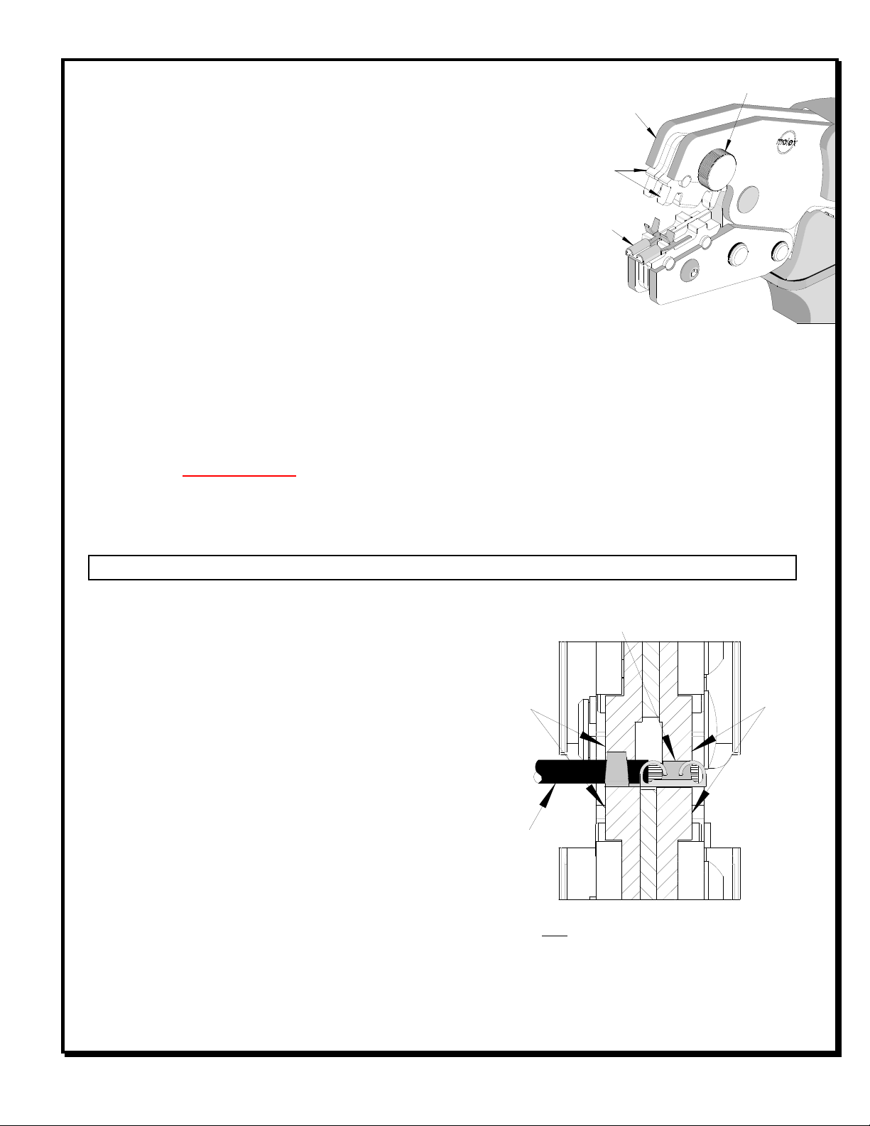
Figure 2
JAWS
OPEN
TERMINAL
NURLED FASTENER
UPPER
TOOLING
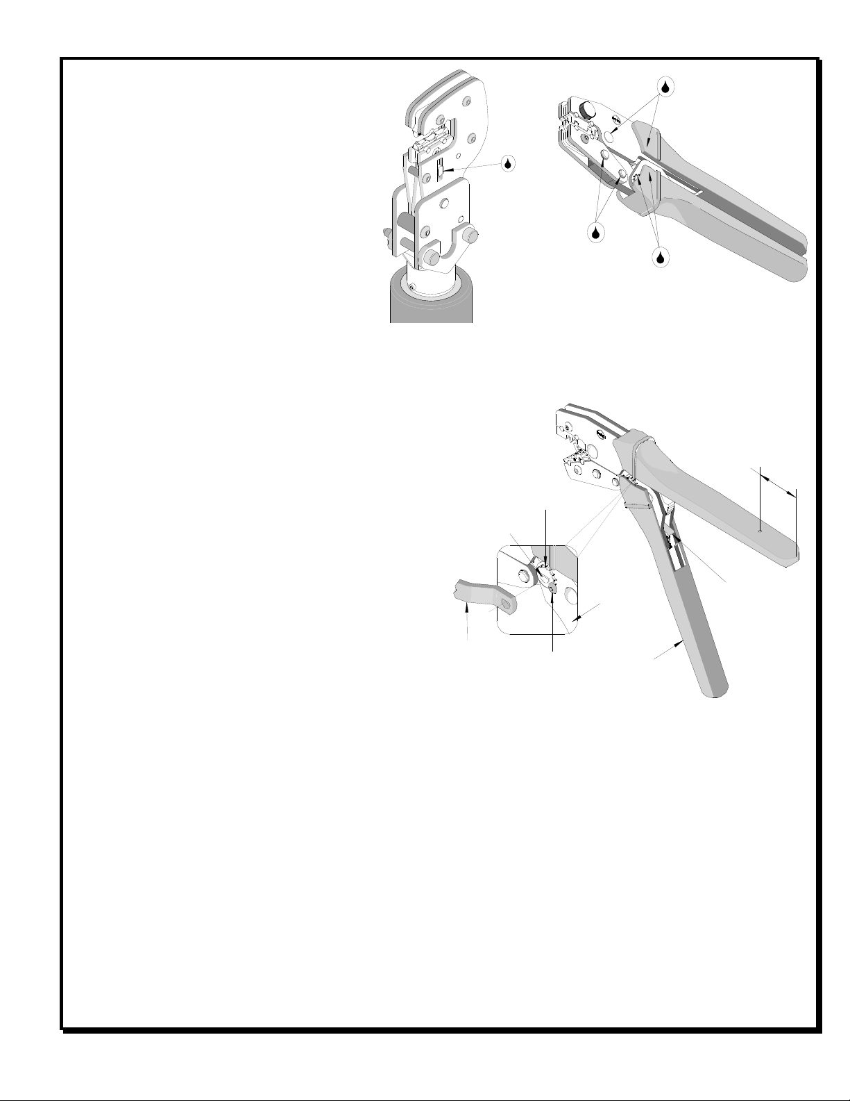
OPERATION
Open the tool by squeezing the handles together, at the end of the
closing stroke, the ratchet mechanism will release the handles, and the
hand tool will spring open.
Crimping Terminals
1. Select the desired terminal listed in the preceding charts.
2. Before attempting to crimp any terminals, make sure all the upper
tooling is correctly placed into the upper jaw. The desired nest
being used for the proper wire size should be in the forward
position, (The marking on the upper tooling “A” for 0. mm ² or “B”
for 0.5mm²). This is done by removing the knurled fastener that
holds the upper tooling in place and then rotating it 1 0° to the correct position. Then, re-installing the
fastener. See Figure 2.
3. Place the terminal into the nest profile, centered on the nest as shown, with the outer edges of the crimp grips
flush with each side of the crimp die and the opening in the terminal centered below the forward leg of the right
punch. See Figure 3.
4. Partially close the tool until the terminal is held in place and re-position the terminal as necessary.
5. From the left side of the tool, insert the pre-stripped wire into the terminal until the conductor is centered, front
to rear, in the crimp grips. See Figure 3.
6. Compress the terminal by squeezing the tool handles until the ratchet mechanism cycle has been completed.
Release handles to open the jaws.
Note: The tamper proof ratchet action will not release the tool until it has been fully closed.
7. Remove the crimped terminal. Inspect for proper
crimp location, and check for insulation closure.
For the Battery Power Tool:
1. Cycle the Battery Power Tool to crimp the terminal
to the wire.
2. Remove the crimped terminal from the terminal
locator by pressing down on the wire stop and
gently pulling on the wire. The terminal locator can
be in either position.
3. Visually inspect the crimped terminal for proper
crimp location.
Maintenance
It is recommended that each operator of the tool be
made aware of, and responsible for, the following
maintenance steps:
1. Remove dust, moisture, and other contaminants
with a clean brush, or soft, lint free cloth.
2. Do not use any abrasive materials that could damage the tool.
Figure 3
Note: The Terminal should be centered in
crimp nests with the outer edges of the crimp
grips flush with the jaws on both sides.
WIRE
CONDUCTOR OF THE TERMINAL CENTERED
IN CRIMP GRIPS FRONT TO REAR
SEE NOTE
BELOW
SEE NOTE
BELOW