manuals.online logo
Brands
  1. Home
  2. •
  3. Brands
  4. •
  5. molex
  6. •
  7. Power Tools
  8. •
  9. molex TM-3000 User manual

molex TM-3000 User manual

The content and copyrights of the attached
material are the property of its owner.
Distributed by:
www.Jameco.com ✦ 1-800-831-4242
Jameco Part Number 1444332
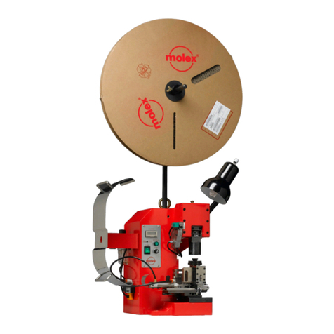
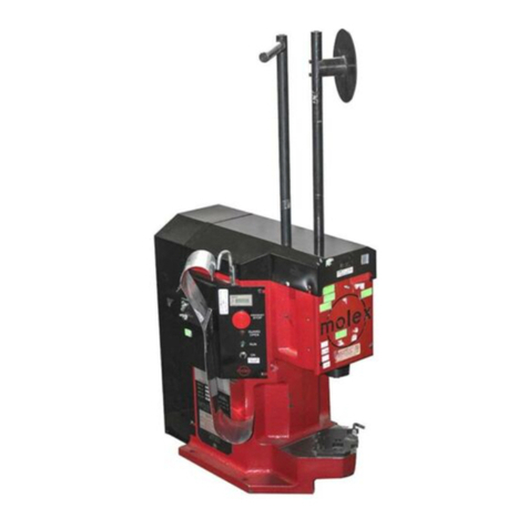
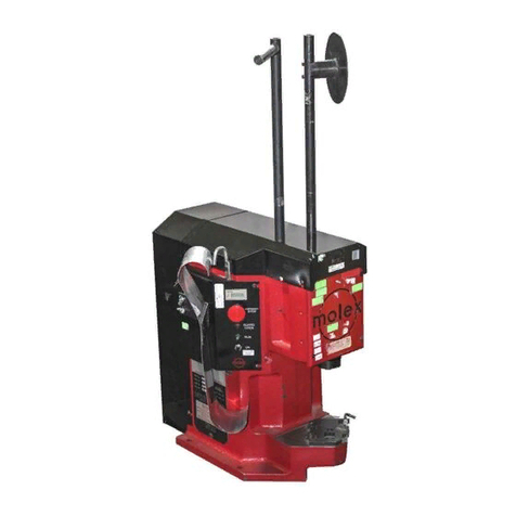
TM-3000UniversalPress
OrderNo63801-7299 ReleaseDate:06-06--05 UNCONTROLLED COPY Page1of29
Revision:A RevisionDate:06-06-05
TM-3000 UNIVERSAL PRESS
UsewithMolexFineAdjustorMini-MacApplicators
Instruction Manual
§Description
§Operation
§Maintenance
TM-3000UniversalPress
OrderNo63801-7299 ReleaseDate:06-06-05 UNCONTROLLED COPY Page2of29
Revision:A RevisionDate:06-06-05
WARNING
NEVER USETHISMACHINEWITHOUTTHEGUARDSORSAFETYDEVICESTHATAREINTENDEDTO PREVENTHANDSFROM
REMAININGINTHEDIESPACE. RUNNINGTHISMACHINEWITHOUTGUARDS,UNDERANYCIRCUMSTANCES,CANCAUSE
SERIOUSINJURY.
NEVER LIFTTHISPRESSWITHOUTTHEAIDOFMECHANICALLIFTINGDEVICES.
NEVER OPERATE,SERVICE,OR ADJUSTTHIS MACHINEORINSTALLAPPLICATORDIESWITHOUTPROPERINSTRUCTIONAND
WITHOUTFIRSTREADINGANDUNDERSTANDINGTHEINSTRUCTIONSINTHISMANUAL.
NEVER SERVICETHISMACHINEWHILEITISCONNECTEDTOANYELECTRICALPOWERSOURCE.DISCONNECTPOWERBY
UNPLUGGINGTHEPRESSFROMITSPOWERSOURCEANDFROMTHECOMPRESSEDAIRSUPPLY.
NEVER INSTALLORREMOVEAPPLICATORDIESWITHTHE MOTORRUNNING,ORAIRSUPPLYCONNECTED.
CAUTION THETM-3000PRESSISSHIPPEDFROMTHEFACTORYATASHUTHEIGHTOF135.80mm(5.346”). FAILURETOHAND
CYCLETHEPRESSWHENINSTALLINGAPPLICATORSCANCAUSESEVEREDAMAGETOTHETOOLINGAND/ORPRESS.
CAUTION MOLEXCRIMPSPECIFICATIONSAREVALIDONLYWHENUSEDWITHMOLEXTERMINALS,APPLICATORSANDTOOLING.
WORK SAFELY AT ALL TIMES
For Service, Contact Your
Local Molex Sales Office
Molex Application Tooling Group
1150E.DiehlRoad
Naperville,Illinois60532
Tel:630-969-4550
Fax:630-505-0049
TM-3000UniversalPress
OrderNo63801-7299 ReleaseDate:06-06-05 UNCONTROLLED COPY Page3of29
Revision:A RevisionDate:06-06-05
Table of Contents
SECTION
1GeneralDescription
2Installation
3Setup-Operation
4MaintenanceandTroubleshooting
5PartsList,AssemblyDrawings,ElectricalSchematics
APPENDIX
AOptions
TM-3000UniversalPress
OrderNo63801-7299 ReleaseDate:06-06-05 UNCONTROLLED COPY Page4of29
Revision:A RevisionDate:06-06-05
Section 1
General Description
1.1 Description
1.2 Features
1.3 TechnicalSpecifications
1.4 DeliveryCheck
1.5 Tools
TM-3000UniversalPress
OrderNo63801-7299 ReleaseDate:06-06-05 UNCONTROLLED COPY Page5of29
Revision:A RevisionDate:06-06-05
General Description
1.1 Description
The63801-7200(120VACversion)andthe63801-7300
(240VACversion)TM-3000UniversalPressisaneconomical,
electrically-operated,single-cycleandsplit cycledirect drive
press. Itisdesignedtoprovideaneffectivemethodofapplying
awide rangeofside-feedandrear-feedterminalstoapre-
strippeddiscretewire orcable. TheTM-3000issuitedtomid-
volumesemi-automaticoperations.
Productionflexibilityisobtainedthroughtheuseof
interchangeableFineAdjustorMini-Macapplicators andmost
IndusrtyStandardApplicators..
TheTM-3000willcompleteonecrimpingcyclewitheach
depressionofthefootpedalandtwodepressionsforsplitcycle.
Safeoperation isprovided byan interlockswitch thatrenders
thepressinoperativeifthesafetyguardisopenedorremoved.
1.2 Features
§UtilizesbothFineAdjustandMini-Macapplicatorssideandrear
feed,andmostindustrystandardapplicators
§PressisshippedsettoIndustryshutheightof135.80mm
(5.346”)
§Idealformid-volume,semi-automaticapplications
§MeetsO.S.H.A.safetystandardsisANSI-Z535.2-2002compliant
§Totallyenclosedforoperatorsafety, includingapowerinterlock
switchforthefrontguard
§Resettablecounterforaccuratebatchcounting
§Modularsolid statecontrolswithan easypluginpowercord
andfootswitch.
1.3 Technical Specifications
Dimensions with reel mounted
Height 1210.00mm(47.60“)
Width 648.00mm (25.50“)
Depth 559.00mm (22.00“)
Unpackedweight 100kg (220lbs)
Power Requirements
Voltage:63801-7200-120VAC60HZ
Voltage:63801-7300-240VAC60HZ
1/4NPTinlet12.7mm(1/2”)Supplypipemin.
Production Rate
2400terminationsperhourmaximum,dependingonoperatorskill
andwirelength.
Processing Capability
Upto 10AWG(5.0mm²)ofcopper conductorinsolidor stranded
wire. (2TonPress)
Sound Level
Operatorwillbeexposedtolessthan85DBA.
1.4 Delivery Check
Afterremovingthepackagingband,thetopandsidesofthebox
shouldliftoffeasily.Thefollowingitemsareincludedinthispackage:
Quantity
MainPressBody 1
ReelSupportAssembly 1
“T”wrenchformanualcycling 1
Carton Contents Quantity
69018-6237PowerCord
(for63801-7200) 1
OR
62500-1774PowerCord220V10A.
(for63801-7300) 1
63801-7271FootPedal 1
63800-7299-TM-3000InstructionManual 1
1.5 Tools
Thefollowingtoolsarerecommendedforsetupand
adjustmentstotheapplicatorinthispress
üMetrichexwrenchset
üSmallstandardscrewdriver
üAdjustablewrench
üNeedlenosepliers
üCrimpmicrometer
üEyeloupe(10x)
üWirestripper/cutter
üEnglishhexwrenchsetforsomenon-metricapplicators
Pneumatic:RequiredforAirFeedApplicatorsonly.
75PSImin.(366KGf/cm2)min.
1.0 SCFM(28.3L/min.
TM-3000UniversalPress
OrderNo63801-7299 ReleaseDate:06-06-05 UNCONTROLLED COPY Page6of29
Revision:A RevisionDate:06-06-05
Section 2
Installation
2.1 Lifting/Mounting
2.2 ReelSupport
2.3 FootPedalandPowerConnection
2.4 PneumaticSupplyHook-up
2.5 TerminalFeedGuide
2.6 FunctionTest
2.7 SafetyandWorkAreaCheck
TM-3000UniversalPress
OrderNo63801-7299 ReleaseDate:06-06-05 UNCONTROLLED COPY Page7of29
Revision:A RevisionDate:06-06-05
2.1 Lifting/Mounting
WARNING:TheTM-3000Pressweighs over100kg(220
lbs);itshouldnotattempttobeliftedbyoneindividual.
Mechanicalliftingdevicesshouldbeused. Apersonlifting
thepresscansustainseverebackorotherinjuries.
Aliftinghookisprovidedonthetopofthe press. A
heavy-dutychain,rope,cable,orbeltcanbeusedwith
loops,links,orringsoneachend thatcansecurelyattach
totheliftinghooks. An electric,hydraulic,ormechanical
craneshouldbe usedto liftthepress. Lift thepress up
approximately12.00mm(.50”)andverifythatthepress
iswell balanced. Upon verification, thepresscan be
liftedontoasturdyworkbench. Accessto theback ofthe
machineis requiredfor manualcycling. A woodenbench
thatisaminimumof25.00mm(1.00”)thickwilloffer
quietvibration-freeoperation. Forthinnerorsheetmetal
tops,theTM-3000canbeattachedtothetablewithtwo
12mmbolts. BoltsarenotsuppliedbyMolex.
2.2 Reel Support
Installthereelsupportintheholelocatedonthetopof
machineframe. Forrearfeed,rotatethereelsupportas
required. SeeFigure2-3. LoosentheM10setscrewthatholds
thereelsupport. Pull upfrom theholeand rotatefor the
properfeedingorientation. Thenslidedownbackintothehole
andtightentheM10setscrew.
2.3 Foot Pedal and Power Connection
Connectthe3-pinplugforthefootpedalintherear ofthe
presscontrolassembly.Turnthelockingring clockwiseuntil
tight. Connectthepowercordplugtothesocketintheback
ofthecontrolassembly. Useagroundedelectrical outletas
thepowersource.SeeFigure2-2.
FOOT PEDAL
ASSEMBLY
PRESS CONTROL
ASSEMBLY
Figure 2-1
OILER ASSEMBLY
MOTOR
REEL SUPPORT
ASSEMBLY
TERMINAL GUIDE
POWER CORD
WORK BENCH
LIFT HOOK WORK LIGHT
TM-3000UniversalPress
OrderNo63801-7299 ReleaseDate:06-06-05 UNCONTROLLED COPY Page8of29
Revision:A RevisionDate:06-06-05
POWER
CORD PLUG
Figure 2-2
FOOTSWITCH
CORD
PULL UP FROM
HOLE, ROTATE AND
SLIDE DOWN INTO
HOLE
REPOSITION
TERMINAL GUIDE
Figure 2-3
REMOVE M6 BHCS
AND REMOVE
TERMINAL GUIDE
LOOSEN
M10 SSS IN
FRONT OF
PRESS
2.4 Pneumatic Supply Hook-Up
Acompressedairsupplyis requiredifairfeedorotherair
poweredapplicatorswillbe used. TheTM3000presscomes
equippedwithanair supplysystem,whichconsists offilter,
regulator,lubricatorand avalve toactuate theairfeedsatthe
propertime inthe presscycle.
Duetotheconsiderabletypesofairconnectionandquick
connectfittingsavailable;Molex onlysuppliesthe TM3000press
witha1/4NPTfemalethreadedfitting. Thecustomermay
attachwhatevertypeofairconnectionsthatare commonlyused
intheirplanttothisport.
Theminimumflexibletubesizeusedtoconnectthepressshould
be8mmor5/16”toassureadequateflowrate.
Afilter-regulator-lubricatorunit issuppliedtoproperlycondition
theincoming air. Thefilter will remove particulate and moisture
fromtheairthatcandamageorreducethelife ofcylindersand
valves. Thisfilterandbowlshould beservicedonaregular
schedule. (Seesection 4.1) Thefilter has anautomatic drainat
thebottomofthebowlthatwillautomaticallyopenandexpel
fluidwhenthebowlisgettingfull. Itisrecommendedthat, a
6mmor1/4”flexibletube,beattachedtothedrainhosebarb
andruntoacontaineriftheairsystem containsexcessive
moisture.
Theregulatoradjuststhepressureof theincomingair towhat
theapplicatorsrequireusually60-80PSI(refertotheapplicator
manualforrecommended pressures.) Adjustmentis
accomplishedbypullingupontheknob,rotatingituntilthe
gaugeindicatesthedesiredpressure,thenpushingitdownto
lockthesetting.
Alubricatorissuppliedforthoseapplicatorairfeedsthatneed
lubrication. Molexair-feedapplicatorsdonot require
lubrication.Thelubricatorisshippedwithoutlubricantinit. To
use,fillthelubricator(makesurethemainairsupplyis
disconnectedorthattheslidevalveprovidedisintheoffposition
beforeaddinglubricant)throughthe fillplugonthetopofthe
unit,withahighqualitySAE10Woil. Thelubricatorhasa
graduateddialontop,turnthedialtothe1or2setting.
Caution:Donotoverlubricate. Onlyaverysmallamountof
lubricantisrequiredto assuresmoothoperation. Excesslubricant
isexhaustedtotheatmosphere.
Iflubricationisnotrequiredsetthedialto0toturn off the
lubricator.
2.5 Terminal Feed Guide
Depending on side or rear-feedapplications,theterminal
guideplateandbracketmustberepositioned.
TheTM-3000pressissetforside-feedapplicatorswhen
shippedfromthefactory. Whenrear-feedapplicatorsare
used,thetwoM6BHCSfromtheterminalguide-mounting
bracketaretoberemoved. SeeFigure2-3. Theguide
bracketisrotated180 degreesandtheassembly isthen
mountedonthetwostandoffsintherearofthepresswiththe
twoM6SHCS. SeeFigure2-3.
TM-3000UniversalPress
OrderNo63801-7299 ReleaseDate:06-06-05 UNCONTROLLED COPY Page9of29
Revision:A RevisionDate:06-06-05
SHUT HEIGHT GAUGE
PRESS QUICK CHANGE
MOUNTING PLATE
Figure 2-4
PRESS
MOTOR ON
PUSH BUTTON
COUNTER
TOGGLE SWITCH
FOR FULL OR
SPLIT CYCLE
Figure 2-5
MAIN
POWER
FUSE HOLDER
2.6 Function Test
WhentheTM-3000isshippedfromthefactory,itissettothe
industryshutheightof135.80mm(5.346”)withacalibrated
loadgauge. The pressshutheight gaugeisspring loadedto
giveanaccuratereadingonthepress shutheight. SeeFigure
2-4. Molexrecommendshandcyclingthepresseachtimean
applicatorisinstalled. SeeSection3-3.
CAUTION:Alwaysmanually cyclethepressbefore
restoringpowertothemachine.
2.6.1Verification of Press Shut Height
Thispress comes factorysetat an IndustryStandard shut height
of135.80mm(5.346”). Alabelisattachedtothefrontof
eachpressindicatingthefactorysettings. Thispresshasan
adjustableshut height,seeSection 3.4.3for crimpheight
adjustment. Alwaysreturnthepresstothefactorysettingon
thelabel beforeinstalling applicatorsto avoidtooling damage.
Checkthe factorysetting periodicallywitha calibratedshut
heightgage.
Shutheightgaugesmaybepurchasedfrom:
ArtosEng. 602-581-0070
KomaxCorp. 847-537-6640
Thegauges shouldcome withinstructionsfor useand
calibration.
2.7 Safety and Work Area Check
Checkthatthecrimpingpositionisergonomic forthe
operator’ssize. A bench height of762.00to813.00mm
(30.00to32.00”)willprovideoperatorcomfort,and
allowsbothfeettorestonthefloor. Thefootpedal
shouldbeplacedin acomfortableposition. Checkthat
thepresspositionislocatedapproximately150.00mm
(6.00“)fromtheedgeofthebench. A chairorstoolwith
adjustableheightandbackrestshouldbeprovidedfor
maximumcomfortandbacksupportforthe operator.
SeeFigure2-5forthecontrolpanel.
CAUTION: Molexrecommendsthattheoperatorand
observersweareyeprotectionwhenthepressisinoperation
orbeingserviced.
Thefuse islocatedon thecontrolpanel. To replacethe
fuse(10AMPon110Vmodelsand5AMPon220V
models),turntheholderinthedirectionasshown. Turn
clockwiseto secure holder in place whenreplaced. See
Figure2-5.
TM-3000UniversalPress
OrderNo63801-7299 ReleaseDate:06-06-05 UNCONTROLLED COPY Page10of29
Revision:A RevisionDate:06-06-05
Section 3
Setup and Operation
3.1 ApplicatorInstallation
3.2 AirFeedApplicatorInstallation
3.3 ManuallyCyclingthePress
3.4 Operation
TM-3000UniversalPress
OrderNo63801-7299 ReleaseDate:06-06-05 UNCONTROLLED COPY Page11of29
Revision:A RevisionDate:06-06-05
QUICK
CHANGE
PLATE
LOCATOR
CLAMPS
LOCKING
CLAMP
USE 4mm
HEX WRENCH
Figure 3-1
ENGAGE
PRESS YOKE
BASE PLATE
LUG BOLT
TO MAIN
AIR SUPPLY
SHUT-OFF
SLEEVE
Figure 3-2
FILTER-REG-LUBRICATOR
SLIDE LEFT TO
SHUT OFF
3.1 Applicator Installation
Powerdownthepress byturningoff the“ON”switchlocated
onthecontrolpanel.
Note: Oncethepressguardisopentheguardinterlock
switchwilldisconnectpowertothemotor.
Steps
1. Swingthepressguardopen.
2. Verifythat theapplicator iscorrectlytooled forthe
terminalbeingused. (Reference specificationsheets
suppliedwiththeapplicator).
3. Cleanthe pressquick changemounting plateof scrapor
chipsthatmayinterferewiththeapplicatorinstallation.
4. Usinga 4mmhex wrench,turn theM5 SHCSclockwise
untilthelockingclampisfullyopened.
5. Locatetheapplicatorlugboltinthepressyoke. See
Figure3-1.
6. Aligntheapplicatorbaseplateslotswiththelocator
clampsonthe pressquick changeplate.
7. Tolockapplicator,turnM5SHCScounterclockwiseuntil
tight.
8. Confirmthattheapplicatorissecuredproperly.
3.2 Air Feed Applicator Installation
Powerdownthepressbyturningoffthe“ON”switch,located
onthecontrolpanel.
Note: Oncethepressguardisopentheguardinterlockswitch
willdisconnectpowertothemotor.
Warning:Whenusingairfeedapplicators,always usethe
slidevalvesuppliedtoshut-offandventairpressuretotheair
feedbefore servicing. Theguardinterlock switchDOES NOT
removeairpressure. Ifanair feedis jammedand airpressure
isnot removed before servicing, the feed could move
unexpectedlyandcauseinjury.
Steps
1. Swingthepressguardopen.
2. Verifythat theapplicator iscorrectlytooled forthe
terminalbeingused. (Reference specificationsheets
suppliedwiththeapplicator).
3. Cleanthe pressquick changemounting plateof scrapor
chipsthatmayinterferewiththeapplicatorinstallation.
4. Usinga 4mmhex wrench,turn theM5 SHCSclockwise
untilthelockingclampisfullyopened.
5. Locatethe applicatorlug boltin the press yoke. See
Figure3-1.
6. Aligntheapplicatorbaseplateslotswiththelocator
clampsonthe pressquickchangemountingplate.
7. Tolockapplicator,turnM5SHCScounterclockwiseuntil
tight.
8. Confirmthattheapplicatorissecuredproperly.
9. Disconnecttheairsupplyfromthefilter-regulator-
lubricatorsuppliedwiththepress,bysliding theshutoff
valvesleevetotheleft,asshowninFigure3-2. Remove
TM-3000UniversalPress
OrderNo63801-7299 ReleaseDate:06-06-05 UNCONTROLLED COPY Page12of29
Revision:A RevisionDate:06-06-05
TOGGLE SWITCH
TO FULL CYCLE PUSH
MOTOR ON
Figure 3-5
POWER
ON
Figure 3-4FOOT SWITCH
CORD
MOTOR
TURN
CLOCKWISE
T-HANDLE
WRENCH
POWER CORD
theplugsfrom thefittings onthe airvalve. Donot
discardtheplugs;whentheairapplicatorisnotbeing
used,thefittingsshouldbeplugged.
Note: Whennotusing anair feedapplicator alwaysshutoffthe
airsupplytothefilter-regulator-lubricatorbysliding the
shutoffvalvesleevetotheleft,theoppositedirectionof the
airflow,as shownin Figure3-2.
Note:Someapplicatorsfeedterminalsintheretractedposition,
forthose air tubesmustbe reversed. In addition,some
applicatorsare airadvance andspringreturn, onthese
applicatorsoneport willneedtobeplugged.
10. Insertthe“A”portof theairvalvewiththetubethat
retractsthefeedmechanismoftheapplicator. See
Figure3-3.
11. Insertthe“B”portof theairvalvewiththetubethat
advancesthefeedmechanism oftheapplicator. See
Figure3-3.
12. Connectthemainairsupplytothefilterreg-lubricator.
(Custumersuppliedfitting)
13. Adjusttheregulatorto75-80PSI(366-390KGf/cm2).
14. Checkthatthetubingfortheapplicatorisproperly
connectedbydrycycling thepressand observingthe
feedmotion.
3.3. Manually Cycling the Press
Powerdownthepressbyturningoffthe“ON”switchlocated
onthecontrolpanel.
Note: Oncethepressguardisopentheguardinterlock
switchwilldisconnectpowertothemotor.
Hand cycling the press is necessary to confirm correct
tool alignment and terminal feed adjustment. It also
gives the setup person the ability to step through the
press cycle manually.
PORT ”B”
Figure 3-3AIR-FEED
APPLICATOR
PORT ”A”
ADVANCES
RETRACTS
FILTER-REG-
LUBRICATOR
TO MAIN
AIR SUPPLY
TM-3000UniversalPress
OrderNo63801-7299 ReleaseDate:06-06-05 UNCONTROLLED COPY Page13of29
Revision:A RevisionDate:06-06-05
Steps
1. Insert the 8mm square socket T-handle wrench through the
access hole in the center of the rear cover on the motor and
locateitintheshaftmotor. SeeFigure 3-4.
2. Rotatethe wrenchclockwise. This turnsthe motorand
movestheramdownandup.
3. Alwaysreturnthepress backtotopdead centerinsuring
thatthe ramis inthestartupposition.
4. RemovetheT-handlewrench.
NOTE: WhentheT-handleisputintothemotorshaftthe
motorturnsoffautomatically.
3.4. Operation
3.4.1 Full Cycle Operation
Caution:Makesurethepressguardisinpositionandall
setupproceduresarefollowed. Followthesafety andwork
areainstructions.
Steps:
1. Pushthetoggleswitchon thecontrolpanelto“FullCycle”.
SeeFigure3-5.
2. Turnthe“Power“switch on,thepowerindicatorlightwilllight
up.
3. Pressthe“MotorOn”pushbutton,the motorindicator light
willlightup. Aftera5seconddelaythepresswillbereadyto
cycle.
4. Placetheprestrippedwirethroughtheslotinthe pressguard
andpushuntilitcontactsthewirestop. SeeFigure3-6.
5. Pressthefootpedaldownonce. Usea sweeping motion to the
rightwiththecrimpedwireandremove.
6. Checkthecrimpedwire andconfirmthatit meetsthe
applicatorspecificationsandvisualinspection.
7. Repeatsteps4and5forthenextcrimp.
3.4.2 Split Cycle Operation
Desription:
Thesplitcycleisusedmostlyforclosedbarrelterminals. This
makesiteasierto locatetheterminalbefore crimpingthe
wire. Thepunch/ramwillclosepartiallytoassistinlocating
theterminalforthetermination. Then thewirecanbeplaced
intotheterminalandbeterminated. To setupthemachinefor
splitcyclepushthetoggle switchonthecontrolpanelto“Split
Cycle”. SeeFigure3-5.
Steps:
1. Depressthefootswitchonce,theramwilllowerpartially,
positioningtheterminalfortermination.
2. Placetheprestrippedwireintotheterminal.
3. Depressthe footswitcha secondtime. Theram willcomplete
itsdownwardstrokeandreturntothetoppositiontocomplete
thecycleofterminatingthecrimp.
Caution:Makesurethepressguardisinpositionandall
setupproceduresarefollowed. Follow thesafetyandwork
areainstructions.
Split Cycle Ram Adjustment
Whensettingupanapplicatorforsplitcycleoperation itmay
benecessarytoadjusttheramforapartiallyclosedposition
(1st position),sotheterminalwillbecaptivatedinthepunch
andnotterminated. Foradjustment, theproxsensorlocated
onthe leftside ofthe ramcover,needs tobe adjusted. See
thefollowingsteps:
Steps:
1. Depressthefootswitchonce,withtheterminalsinthe
applicator. Seewherethepunchislocatedinthe1st position
ofthecycle.
2. Ifthepunch istoo highanddoes notcenter theterminalso
thattheprestrippedwirecanbeinsertedintheclosedbarrel
orthepunchistoolowpartiallycrimpingtheterminal, the
proxsensor needsto beadjusted.
WIRE
STOP
PRE-STRIPPED
WIRE
Figure 3-6
GUARD
TM-3000UniversalPress
OrderNo63801-7299 ReleaseDate:06-06-05 UNCONTROLLED COPY Page14of29
Revision:A RevisionDate:06-06-05
ADJUSTABLE
DIAL
LOOSEN
M6 SHCS
Figure 3-8
LOOSEN
M6 SHCS
1.52mm
(.06”)
MAX. GAP
M4 JAMNUT
Figure 3-7
PROX SENSOR
M12 JAM NUT
PROX BRACKET
TOGGLE SWITCH
TO SPLIT CYCLE
3. Openthepressguard.
4. LoosenthetwoM12jamnutsonthesplitcycleprox,located
onbothsidesoftheproxbracket. ThenloosentheM4 jam
nutholdingtheM4X25SHCS. Turnthescrewclockwiseto
raisetheprox or counter-clockwiseto lowertheprox. See
Figure3-7. Raisetheproxifthepunchispartiallycrimping
theterminal;orlowertheproxiftheramis notclosingfar
enoughandnot centeringtheterminalpunch.
5. RetightentheM4SHCSandthe(2)M12jamnutspositioning
theproxforthe1st positionofthesplitcycle. SeeFigure3-7.
6. Closethepressguard.
7. Repeatstep1tocheckforthecorrectpositionoftheram. (Be
sureRamisatTop-Dead-Centerfirst.)
Note: Thegapbetweentheproxandtheramshouldbe
1.52mm(.06”)Max. SeeFigure3-7.
Caution:Alwaysreturntheramtothetopdeadcenter
positionor startposition ofthe cyclebefore recyclingthe
press. Thisis donebymanually cyclingthepress. See
section3.2.
3.4.3 Crimp Adjustment
SeeSection2.6.1 forIndustrystandardshutheight.
Crimp Adjustment Full and Split Cycle
Ifcrimpadjustment isrequired andcannot bemadebythecam
adjustmentontheapplicator,thefineadjustmentdialonthepress
ramcan be adjustedbyfollowingthestepsbelow.
Steps:
1. Openthepressguard.
2. LoosenthefourM6SHCSsonthefrontofthepress.
3. Rotatetheadjustmentdialtotherighttoraisecrimpheightor
tothelefttodecrease. Dialindicatorlinesrepresent
incrementsof.05mm (.002”). SeeFigure3-8.
4. Whenadjustmentiscomplete,retightenthefourM6SHCSs.
5. Closetheguard.
6. Placeaprestrippedwireintotheterminalandterminateunder
power. Examinethequalityofthecrimp.
7. Repeatsteps1 thru6ifthedesiredcrimpisnotachieved.
Usecautionadjustingthe ramdownward. Overadjustment
inthisdirectionmaycausetoolingdamageorbreakage.
Alwaysreturn theadjustment tothefactory settingbefore
installing another applicator, or recalibrating shutheight.
SeeSection2.6.1.
TM-3000UniversalPress
OrderNo63801-7299 ReleaseDate:06-06-05 UNCONTROLLED COPY Page15of29
Revision:A RevisionDate:06-06-05
Section 4
4.1 Maintenance
4.2 Oiler
4.3 Troubleshooting
TM-3000UniversalPress
OrderNo63801-7299 ReleaseDate:06-06-05 UNCONTROLLED COPY Page16of29
Revision:A RevisionDate:06-06-05
OIL CUP
GREASE FITTINGFigure 4-8
LID
TUBE
WICK
(PKG OF (25
#638900727)
MOUNTING
BRACKET
JAR
(OIL RESERVOIR)
Figure 4-9 OILER ASSEMBLY
4.1 Maintenance
Powerdownthe pressbypressingthepower button
tooff“O”locatedonthecontrolpanel.
TheTM-3000pressrequiresverylittlemaintenance.
ForefficientoperationtheTM-3000press shouldbe cleaned
dailywithasoftbristlebrushtoremoveanycarrierstrip
debrisandterminalplatingdustfromthetoolingarea.
Maintenance Schedule
Thefollowingis offeredasageneralguidelineformaintenance.
Toollifecanbe increasedwithgoodmaintenance practicesor
decreasewithlackofmaintenance.
Item Frequency
Cycles Frequency
Time Materials
Air Filter 100,000 Weekly Clean bowl and sintered
filter with denatured alcohol
AirLubricator 100,000 Weekly SAE 10W oil. Check and
refill if used
Ram 25,000 Daily SAE 10W oil
Oil Cup (Top of ram)
Main Bearing 25,000 Daily Grease fitting right side of
Press bearing lube
Cleaning 25,000 Daily Use soft bristle brush on
Applicator mounting plate
4.2. Oiler
Description
ThewickactionoilerisincludedwiththeTM-3000Press. The
oilerappliesathincoatoflubricanttotheterminals,which
helpswithfeedingandbetterreleasefromtermination
punches. Theoileris primarilyusedforterminalswithgold
plating. Toavoid contaminationwhen shippedandduring
setup,theoilerisshippedfromthefactorywithno lubricantoil.
Theoiler shouldonly beused onapplicators thatrequire
lubricationfor smooth trouble-freeoperation.
Oiler Position
Adjustthepositionoftheoilerunitusingthemountingscrew
thatattachestheoilertothequickchangemountingplate.
Simplyloosenthescrew,slidetheunittothedesiredposition,
andtightenthescrew. Theunit can be removed and placed
ontherearsideofthequickchangemountingplateforrear-
feedapplications.
Oiler Wick
Adjusttheheightoftheoilerwickbypullinguporpushing
downonthe wickto theappropriateheight. The wickcan be
movedusing pliers or simplygrabitwithyourfingers.
Filling the Reservoir
Whilefirmlyholdingthe lid,screwthejar (oilreservoir)
counterclockwise untilitis removed. Fillthejar withthe
desiredlubricantoil andreplace thelid.
TM-3000UniversalPress
OrderNo63801-7299 ReleaseDate:06-06-05 UNCONTROLLED COPY Page17of29
Revision:A RevisionDate:06-06-05
Replacing the Wick
Whilefirmlyholdingthelid,screwthejaroilreservoir)
counterclockwiseuntil itis removed. Feedanew wickup into
thetubeuntilitprotrudesfromthetopendofthetubeand
replacethelid.
Package of 25 Wicks: Molex Order No: 63890-0727
Lubricant Oil
Recommendedoil:TransdrawB-19
Vendor: SureLubricantsInc.
356SouthLivelyBoulevard
ElkGroveVillage,IL60007-2010
Phone:888-787-3582
Fax:847-956-6655
E-mail:[email protected]
TM-3000UniversalPress
OrderNo63801-7299 ReleaseDate:06-06--05 UNCONTROLLED COPY Page18of29
Revision:A RevisionDate:06-06-05
4.3 Troubleshooting
Symptom §Cause Solution
§Power/Powercordfailure Checksupply
§Looseconnection Refertocontrolschematic
§Guardinterlockswitchdisengaged Re-Installguard
§Fuseblown Replace
§On/Offswitchfailure Replace
§Motorfailure Replace
§T-wrenchnotremovedfrommotor
RemovedT-wrenchfrommotor
§ControlPCBnotworking Replace
§Solidstaterelaynotworking Replace
Motorwillnotrun
§Controlboardformotor Repairorreplace
§Guardinterlockswitchdisengaged Re-Installguard
§Faultyfootswitch CheckConnection. Repairorreplace
§ControlPCBnotworking Replace
Presswill not cycle
§Fuseblown Replace
Presspartiallycycles §Toggleswitchsettosplitcycle Resetthetoggleswitchtofullcycle
TM-3000UniversalPress
OrderNo63801-7299 ReleaseDate:06-06-05 UNCONTROLLED COPY Page19of29
Revision:A RevisionDate:06-06-05
Section 5
5.1 PartsList
5.2 AssemblyDrawings
5.3 ElectricalandPnuematicSchematics

Other manuals for TM-3000

3

Other molex Power Tools manuals

molex RHT 2251 User manual

molex

molex RHT 2251 User manual

molex 63600-0478 User manual

molex

molex 63600-0478 User manual

molex 63801-8550 User manual

molex

molex 63801-8550 User manual

molex 57131-6000 User manual

molex

molex 57131-6000 User manual

molex 69020-2025 User manual

molex

molex 69020-2025 User manual

molex 63811-0300 User manual

molex

molex 63811-0300 User manual

molex 90327 Series User manual

molex

molex 90327 Series User manual

molex VHDCI User manual

molex

molex VHDCI User manual

molex 63823-5700 User manual

molex

molex 63823-5700 User manual

molex 207129 Series User manual

molex

molex 207129 Series User manual

molex 63819-7300 User manual

molex

molex 63819-7300 User manual

molex TM-3000 User manual

molex

molex TM-3000 User manual

molex TM2000 User manual

molex

molex TM2000 User manual

molex TM42 User manual

molex

molex TM42 User manual

molex TM-3000 User manual

molex

molex TM-3000 User manual

molex 63827-2000 User manual

molex

molex 63827-2000 User manual

molex 63816-1700 User manual

molex

molex 63816-1700 User manual

molex 43375 User manual

molex

molex 43375 User manual

molex 11-31-6356 User manual

molex

molex 11-31-6356 User manual

molex 64000-0041 User manual

molex

molex 64000-0041 User manual

molex 63811-7500 User manual

molex

molex 63811-7500 User manual

molex AT-200 Manual

molex

molex AT-200 Manual

molex 69020-0660 User manual

molex

molex 69020-0660 User manual

molex 63816-0200 User manual

molex

molex 63816-0200 User manual

Popular Power Tools manuals by other brands

Bullet tools Magnum 909 quick start guide

Bullet tools

Bullet tools Magnum 909 quick start guide

Logosol GRINDLUX 4000 user manual

Logosol

Logosol GRINDLUX 4000 user manual

Stanley FatMax instruction manual

Stanley

Stanley FatMax instruction manual

MONKEY GRIP SPEED DRIVE 17045-MG Instructions for use

MONKEY GRIP

MONKEY GRIP SPEED DRIVE 17045-MG Instructions for use

Atlas Copco LTV39-2 R56-HAD Product instructions

Atlas Copco

Atlas Copco LTV39-2 R56-HAD Product instructions

Vestil PLBS Series instruction manual

Vestil

Vestil PLBS Series instruction manual

Prebena 11-WP130 instruction manual

Prebena

Prebena 11-WP130 instruction manual

MaxPro PROFESSIONAL MPHG2001 manual

MaxPro PROFESSIONAL

MaxPro PROFESSIONAL MPHG2001 manual

Stihl KMA 130 R instruction manual

Stihl

Stihl KMA 130 R instruction manual

Vermason TB-7531 Technical bulletin

Vermason

Vermason TB-7531 Technical bulletin

WOLFF Weldliner Series operating instructions

WOLFF

WOLFF Weldliner Series operating instructions

Applifast AirPower Series Repair manual

Applifast

Applifast AirPower Series Repair manual

Makita HG 5010 manual

Makita

Makita HG 5010 manual

Varan JHS-1100 user manual

Varan

Varan JHS-1100 user manual

stayer MINI COM 12V operating instructions

stayer

stayer MINI COM 12V operating instructions

Ryobi RR14W4 manual

Ryobi

Ryobi RR14W4 manual

Trumpf TruTool TKF 700 Operator's manual

Trumpf

Trumpf TruTool TKF 700 Operator's manual

HRS HT302 instruction manual

HRS

HRS HT302 instruction manual

manuals.online logo
manuals.online logoBrands
  • About & Mission
  • Contact us
  • Privacy Policy
  • Terms and Conditions

Copyright 2025 Manuals.Online. All Rights Reserved.