Tool Kit for 18-24 AWG Crimp Terminals
Doc No: ATS-6381133HM Release Date: 11-19-03 UNCONTROLLED COPY Page 6 of 11
Revision: D Revision Date: 10-04-10
TERMINAL FLUSH WITH
INSULATION TOOLING
Crimping Terminals without a Locator
1. With the hand tool in the open position, select the proper profile.
2. Position the terminal in the proper profile; partially close the hand
tool until the terminal is held in place. The terminal should be
positioned so that the front of the insulation grips is flush with the
front face of the insulation tooling. See Figure 5A.
3. Gently slip the wire into the terminal, and then position the
insulation and stripped strands into the terminal insulation and
conductor grips. Note: No wire stop is provided. If the wire will not
fit into the partially closed tool, due to large insulation diameter, the
terminal and wire must then be placed in the open tool. Applying
slight downward pressure on the wire may help hold the terminal in place while crimping.
4. Compress the terminal by squeezing the tool handles until the ratchet mechanism cycle has been completed.
Release handles to open the jaws.
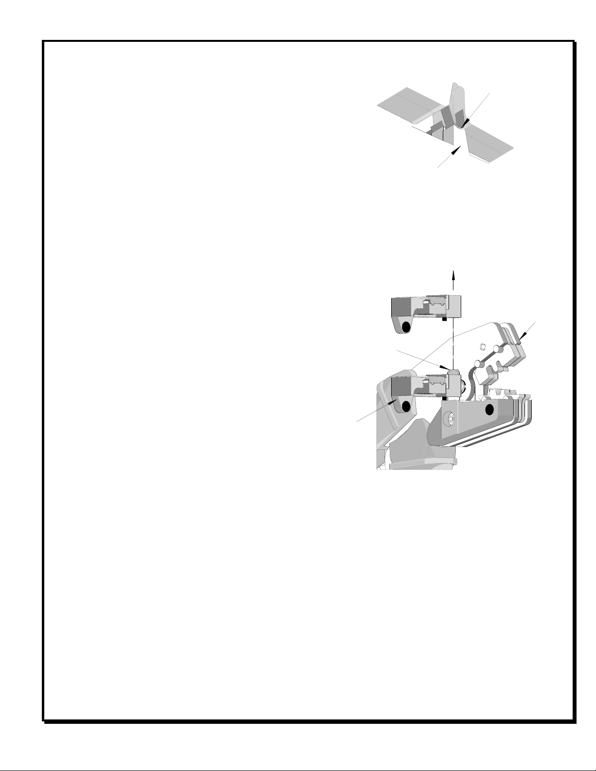
Locator Change Over
Two styles of locators are provided with the crimp hand
tool 63811-3300. They are locator no. 1 (63811-3375),
which is black and locator no.2 (63811-3376), which is
gray. Make sure the desired style of locator is installed
for the proper terminal and wire. Follow the steps
below to change the locators.
1. Open the crimp hand tool.
2. Swing the existing locator open and away from the
hand tool.
3. Firmly press down on the brass pivot shaft with
your thumb, while pulling the locator up. Slip the
locator off the top of the brass pivot shaft. See
Figure 6.
4. Replace it with the desired locator by putting over the brass pivot shaft and snapping it into place.
Maintenance
It is recommended that each operator of the tool be made aware of, and responsible for, the following maintenance
steps:
1. Remove dust, moisture, and other contaminants with a clean brush, or soft, lint free cloth.
2. Do not use any abrasive materials that could damage the tool.
3. Make certain all pins; pivot points and bearing surfaces are protected with a thin coat of high quality machine
oil. Do not oil excessively. The tool was engineered for durability but like any fine piece of equipment it needs
cleaning and lubrication for a maximum service life of trouble free crimping. Use a 30 weight automotive (light)
oil used at the oil points, every 5,000 crimps or 3 months, shown in Figure 7A or 7B will significantly enhance
the tool life.
4. Wipe excess oil from hand tool, particularly from crimping area. Oil transferred from the crimping area onto
certain terminations may affect the electrical characteristics of an application.
PRESS DOWN ON
BRASS PIVOT SHAFT