Molnar MF1705-93-OH-3T User manual

important procedural note:
after installation, please complete
the Installer Checklist on page 19
to assist with workshop
administration and warranty
ALL ROUNDER
INSTALLATION
Installation for Molnar
Two Post Hoist (3 Tonne)
MF1705-93-OH-3T
OH
OL
4T
AS
BASE

Molnar Hoists All Rounder Installation
2
As the policy of Molnar Hoists is one of continuous improvement, the manufacturer reserves the right to change specifications
without notice. Information is correct and true at time of printing (July 2012)
Parts Glossary 03
Pre Installation - Equipment 04
Pre Installation - Packing List 05
Pre Installation - Flooring Requirements 06
Installation - 2 Unpack and position 07
Installation - 3 Pre Assemble 07
Installation - 4 Raise posts 08
Installation - 5 Square & Secure 09
Installation - 6 Fit Top Brace 09
Installation - 7 Run Long Wire Rope 10
Installation - 8 Pulley Installation 10
Installation - 9 Install Motor 12
Installation - 10 Power Hoist 13
Installation - 11 Install Arms & Auto Arm Locks 13
Installation - 12 Final Adjustment 15
Installation - 13 Lubricate, Test & Install Covers 16
Electrician Notes 18
Hydraulics Notes 18
Installer Checklist 19
Key
General warning
Electrical hazard
Installation tip
Terminology
From time-to-time product or process descriptions can
change or evolve, for the purposes of clarity:
cables = wire ropes
pulleys = sheaves
shafts = pulley pins
safety = lock
lift pads = pick-up pads
release lever = lowering handle
Contents
Contents
This is owner manual 2 of 4

Molnar Hoists All Rounder Installation 3
Parts Glossary & Location
Non-Control-Post
Control-Post
Cover
Top Pulley
Limit Switch Activating Bar
Beam
Motor
Oil Tank
Pick-Up Pad
Pivot Pin
Split Pin
Post Cover Bracket
Top Pulley
Wire Rope Cover
Conduit
Dust Cap
Control-Post Cap
Non-Control-Post Cap
Carriage
Arm
Post Cover Bracket
Wire Rope
Base Bolts
Anchor Bolts
Parts Glossary

Molnar Hoists All Rounder Installation
4
Personal protective equipment
óGloves
óEar & eye protection
óSteel capped boots
óSafety cones, warning signs and tape
Electrician
A licensed electrician must perform all
electrical work including power connection
and wiring (see Section 10 Power the Hoist)
power requirements
3 Phase, 3 HorsePower, 415 Volt. Requires 3 Phase and Earth,
5 Amp.
OR 240 Volts under load at motor, hard wired on 20 Amp
circuit (if installing an optional Single Phase motor)
Lubricant recommended
óGrease > Marine grade wheel bearing grease
eg. molybdenum grease
óDry lubricant > CRC dry glide
> Wurth HHS dry lube
óGeneral lubricant > CRC Tac-2
> Wurth HHS Lube
óWire Rope lube > Lanotec heavy duty liquid lanolin
> 85-90 gear oil
óHydraulic oil >5 litres AWH46
(supplied with hoist)
Materials
ó16 sleeve anchors (bolts): 20mm
diameter by a minimum 100mm
in length with an M16 thread.
Note depending on the floor condition and the amount
of shimming, longer anchors may be required.
Note “ 100mm” refers to the length of the sheaf (not the
overall length of the bolt)
Note Some authorities do not approve expanding type
anchorage devices.
ó An assortment of shimming in various thicknesses.
Note shimming should be minimum size of 50mm
square and either zinc steel or construction grade plastic.
Pre Installation - Equipment
Tools
ó2.4 metre platform-style step ladder
or an appropriate elevated work platform
óCrane or appropriate lifting device
óPallet jack or appropriate material handling device
ó1200mm spirit level
óPry bar - heavy and light duty
óHammer drill with a 20 mm masonry drill bit
óAir Impact Gun with 24 mm socket
óTin snips
óPull cable (1.2 m, capable of pulling electrical cable
through conduit)
ó2 tape measures
óChalk line
óOil funnel with an end to fit into a W bsp hole
óStandard tool kit
>2 screwdrivers
>Phillips Head screwdriver
>Spark plug socket - 5/8” or 16mm
>Allan Key, 6mm and 3mm
>Clamp wrench (AKA vice grip)
>Cutting pliers (AKA wire cutters)
>Rubber mallet
>Hammer
>Adjustable wrench
>Spanner (16mm, 10mm and 13/16th imp)
>Shifting spanner - 450mm
>Socket set
>Needlenose pliers
>External circlip pliers
>Box cutter
>Black Texta
100mm
Pre Installation Molnar Hoists All Rounder Installation

Molnar Hoists All Rounder Installation 5
Check all items are available prior to assembly.
Pre Installation - Packing List
Control
Post
End Cap
Non-
Control
Post End Cap
Non-
Control Post
top Pulley
Control
Post bottom
Pulley
Large timber crate contents
Auto Arm Lock Kit
(for contents: See Page 14)
Motor unit
5l Oil
Non-Control Post, with carriage
4 x Arms
Control Post, with carriage (identified by the conduit)
Small timber crate contents
Wire Rope Cover
Limit Switch Activation Bar
Top Brace
2 x Post Covers
Lowering Handle
2 x Post Cover Bracket
Control post dust cover
4 x flat M10 Washer
20 x 12mm M10 Bolt
2 x 12mm M2.5 Bolt
4 x 10mm M6 Bolt
Roll Pin
Spring
Bracket
Sleeve
2 x Linkage toggles 3 x Split pin
4 x Door Protectors
2 x flat M5 Washer
2 x speed clips
4 x
pivot pin
Note: Post covers are identical,
but the Control-Post cover has
Operation Instruction Decal
Pre Installation

Molnar Hoists All Rounder Installation
6
Pre Installation - Flooring Requirements
Pre-Installation
Slab / Floor
It is the owners responsibility to provide a
satisfactory site area.
1 The floor should be a single reinforced concrete slab.
>Minimum concrete thickness = 100mm
>Prepared base 100mm thickness of quarry rubble
compacted to 95%
>25 Mpa concrete
>SL81 reinforcement mesh
>Minimum thickness of concrete above mesh = 65mm
>Minimum plan dimensions of 4600mm x 1800mm
2 The floor must be flat and level.
A level tolerance between posts of 10mm is allowable.
Check with straight edge and spirit level.
3 The reinforcement should be selected and located to
accommodate a bending moment of 10.72 E6 Nmm
at the end of the steel footing attached to each post.
The concrete footing must comply with AS3600-1994
concrete structures.
4 If there is any doubt about the quality of the floor, a
replacement slab should be installed. Use a qualified
person to design the replacement slab.
No liability for any damages will be accepted should
the hoist be installed on an unsuitable floor
1 Site / Position
Cordon off work area using safety
cones or other safety barricade.
Ensure area is clear of any
obstruction prior to installation
Overhead clearance of 4000mm
Site should have a 600mm walk way around the
hoist and vehicle. If clearances are not available
consult Molnar Hoists for advice.
1 Measure and mark required clearances around the site
– minimum 3500mm in front of hoist and 600mm side
clearance.
2 Measure overall hoist width (3250mm) and mark
external edges.
3 Use a chalk line to mark the centre line of the posts and
mark the centre point (1625mm).
4 Measure 1325mm off each side of the centre point and
mark internal edges using a ‘V’ symbol, to ensure the
marking is visible when positioning and sliding post into
place.
2650
3250
600 600
600
3500
1625
1325
vv
x
x
10mm
100mm
65mm
3250mm
4600mm
1800mm

Molnar Hoists All Rounder Installation 7
2 Unpack and position
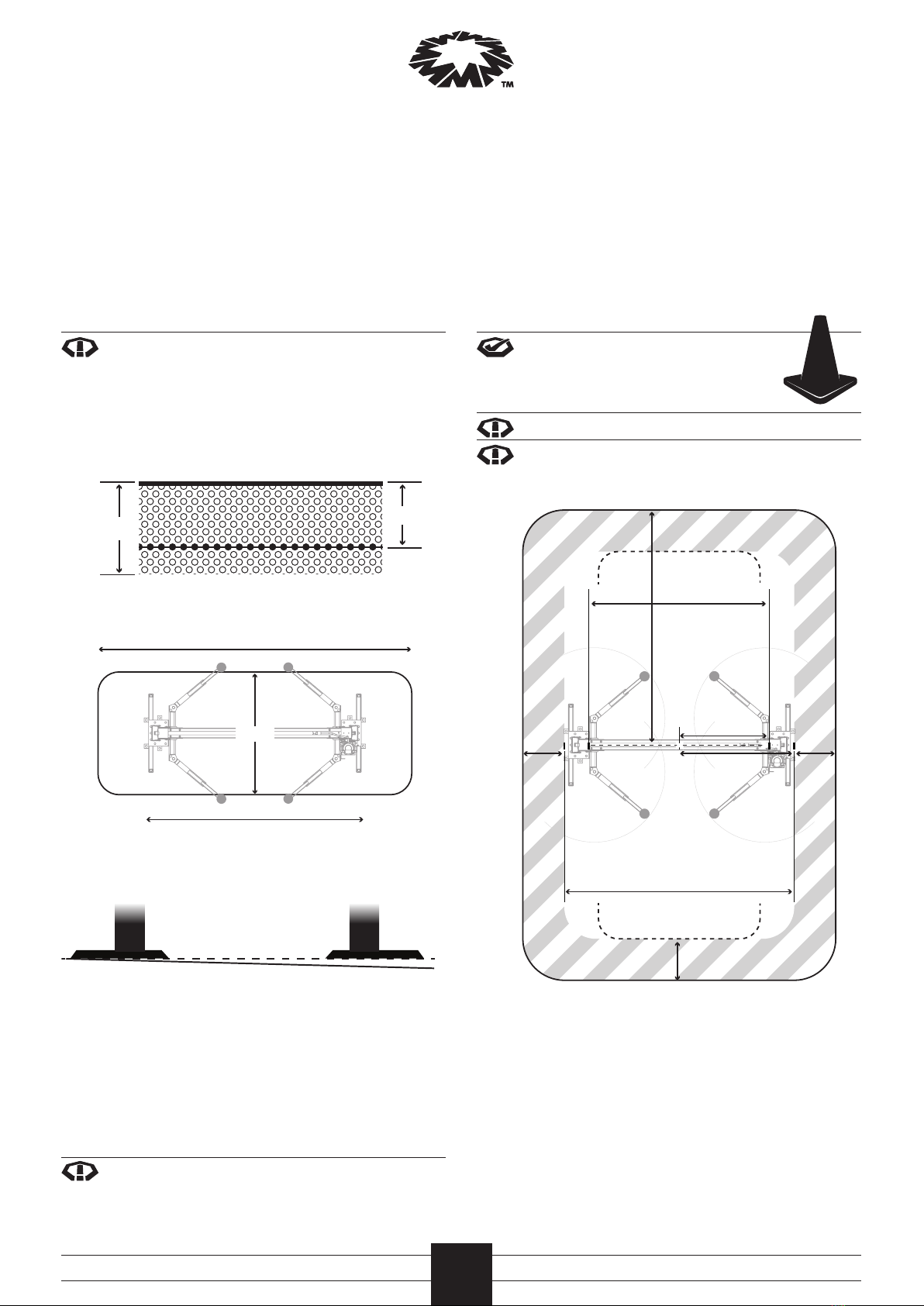
1 Using a pallet jack, position hoist in front of the marked
line.
2 Cut bindings and remove the plastic cover. Cut the steel
strapping around the two timber crates. Open crate lids
with pry bar and lay out contents on the floor, clear of the
working area. Discard crates and packing material.
Plastic cover can be used to collect packaging refuse
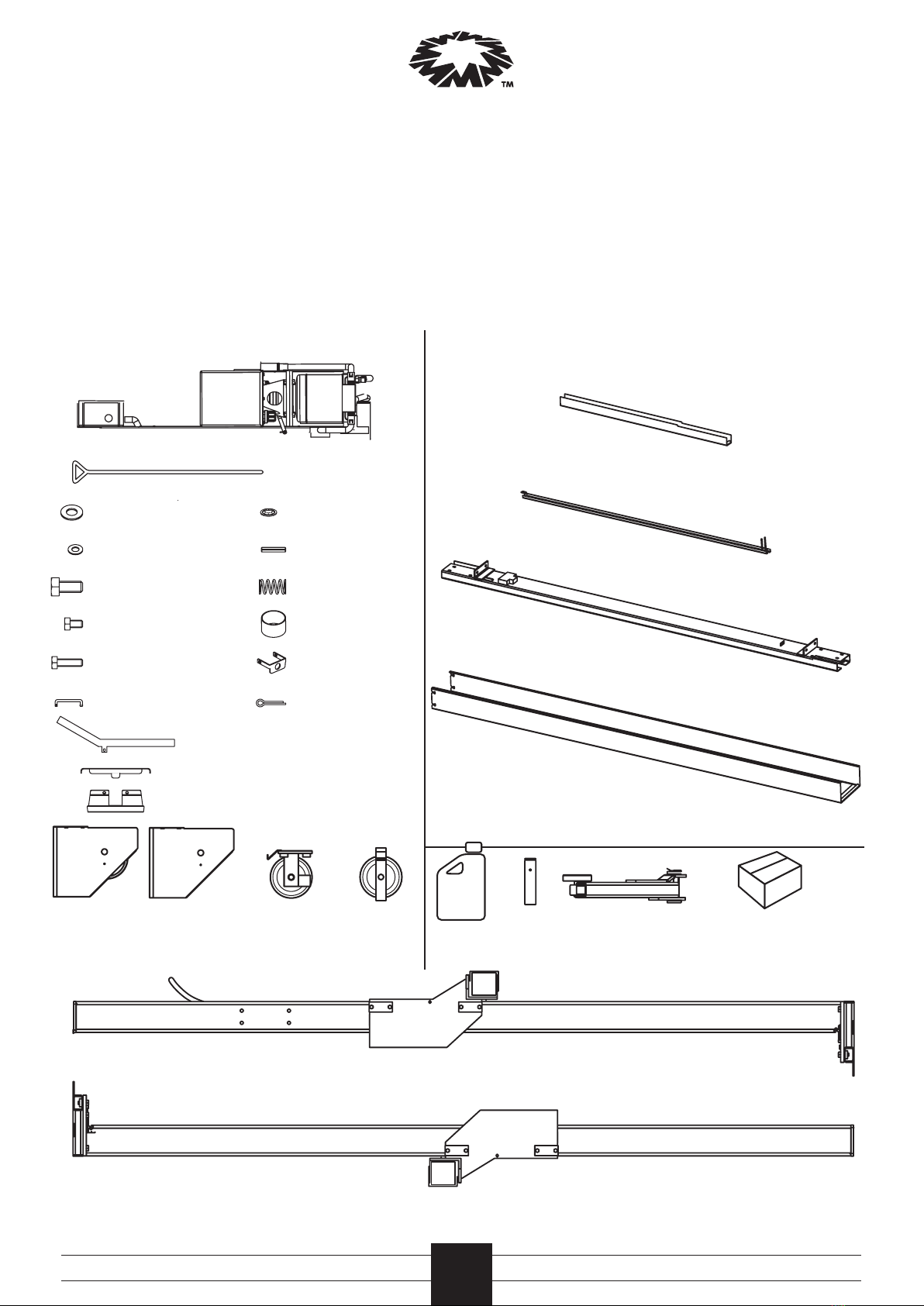
3 Carefully check contents against the packing list on
the previous page. If any contents are missing, stop
installation and immediately contact your distributor.
4 Remove strapping holding the lifting arms to the hoist.
Discard strapping and set lifting arms aside.
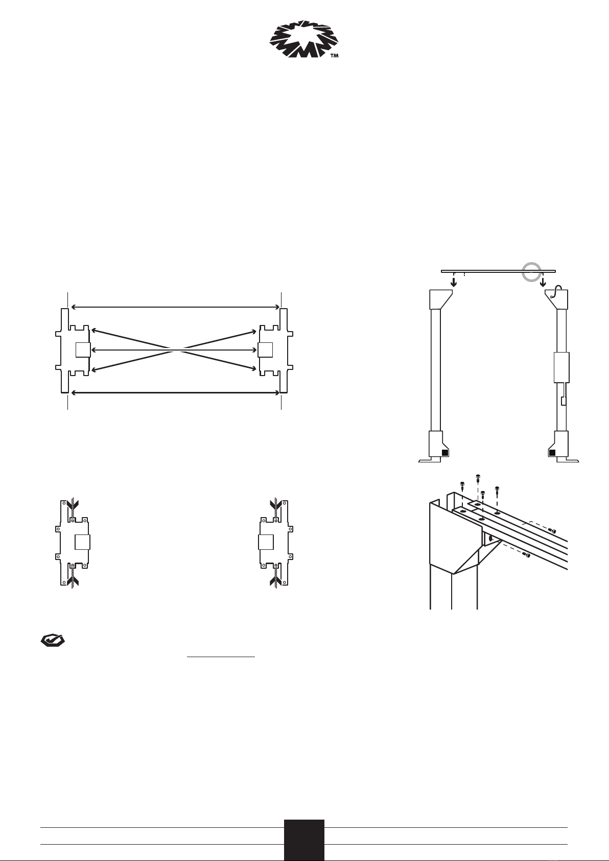
5 Locate the control-post (identified by the conduit).
Position hoist so that the base of the control-post is
positioned on the preferred side for motor operation.
6 Once correctly positioned, lower the pallet jack until the
packing legs are touching the ground but the post are
still supported by the pallet jack.
7 First cut away the strapping from around the carriage
and then cut away the remaining strapping from around
the hoist.
Do not cut strapping on the control post marked
with red and white sticker, this strapping must
remain until posts are upright.
8 Lower hoist and carefully remove pallet jack
9 Using the pallet jack or pry bar, carefully separate the
posts to create about a 200mm gap between them.
3 Pre assemble
1 Working first on the non-control post, use the pallet jack
to lift it up to remove the load on the packing leg. Using
an Air Wrench, undo the 2xM16 bolts and nuts holding
the packing leg to the base frame. Remove the packing
leg and refit the M16 nuts and bolts to it ready for return.
2 Repeat this process for the control post
Packing legs must be returned to distributor
or place of purchase for full refund of deposit
3 Working on the control-post, place the pallet jack under
the top end, raise slightly and swing the top clear of the
other post.
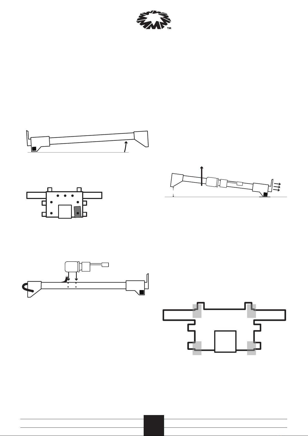
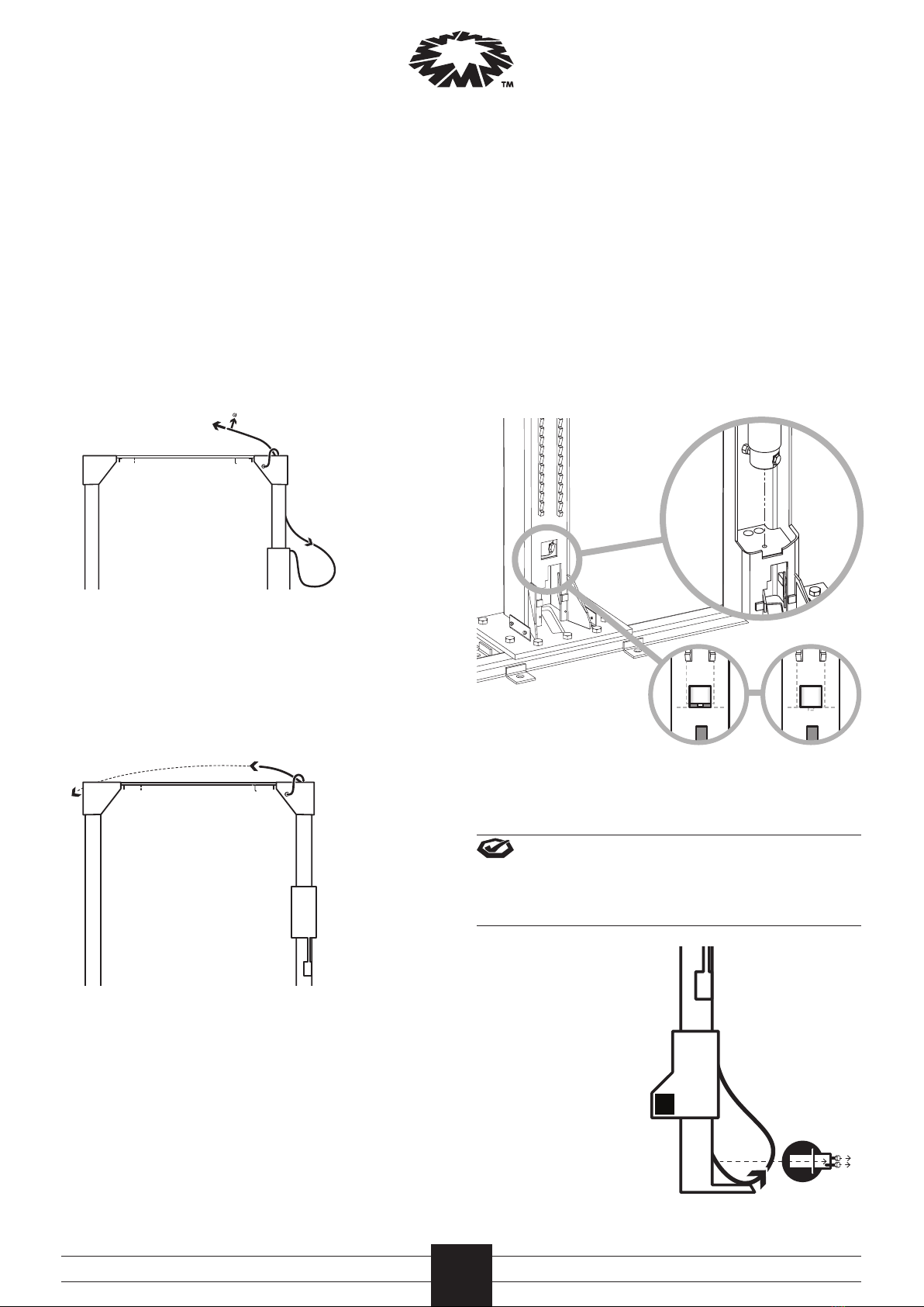
4 Pull the conduit through the top of the control-post,
twisting as you pull, until approximately 150mm is left
protruding from the side of the post.
5 Locate the control-post cap: a. unscrew the M6 bolt
holding the pulley in the control-post cap. b. Support the
pulley while removing the pin. c. Remove the pulley and
set to one side, ensuring both pulley spacers have also
been removed.
6 Fit control-post cap to control-post: feed the conduit
through the top of the control-post cap while sliding
the cap onto the control-post. Tuck the conduit into the
pulley hole to secure during installation.
7 Lower to ground and remove the pallet jack.
d
e
s
i
r
e
d
l
o
c
a
t
i
o
n
o
f
c
o
n
t
r
o
l
-
p
o
s
t
control-post
intended location of hoist
base
150
Installation
6a. unscrew bolt 6b. remove pin
6c. remove pulley
Installation

Molnar Hoists All Rounder Installation
8
4 Raise posts
1 Using the pallet jack, position the control-post over the
centre chalk line with base in the approximate position.
2 Use a lifting device (such as crane) to raise the post.
Place a sling or other strapping around post (above the
twin pulley, ensuring the sling position is above the
centre of gravity) and raise the top of the post up 300mm.
Slide the post down through the carriage until the
locking toggles click at least three times.
3 Continue to raise the post until it is vertical, then
carefully manoeuvre until in-line with centre and
distance markings, and lower. Check the stability of the
post before removing sling and lifting device. In the event
of an uneven floor surface, a shim may be required under
the corner of the base to stabilise the post.
4 Repeat process for the other post.
5 Remove the top strapping and block (with red and white
sticker) from around the control-post.
6 Using a spirit level, check each post is vertical on both
plains. Adjust by shimming between the base frame and
floor as needed. Refer to the diagram below for correct
shim points.
To level and stabilise posts, shim at the points marked with an X, until gaps are filled.
Installation
Installation
9 Working on the non-control-post, place the pallet jack
under the top end, raise slightly and swing the top clear
of the other post. Raise post approximately 500mm
before sliding on the non-control-post cap.
10 Lower to ground and remove the pallet jack.
11 Using an air impact gun, remove the M16 bolt holding
the packing timber to the base of each post, discard the
timber and refit the bolt.
12 Check all base bolts are tight.
13 Fit 4 x M10 bolts halfway into the side of the control-post.
Slide the motor onto these bolts and tighten (motor
mounting holes are elongated to aid fitting).
300mm
xx
xx

Molnar Hoists All Rounder Installation 9
5 Square and secure
1 Check distance between posts is correct
(exactly 2650 mm) and adjust as needed.
2 Check both posts are parallel and square to each other.
Using two tape measures, measure between each side of
the base frame and adjust until even.
3 Recheck the distance between the posts to ensure they
have not moved during any adjustments.
4 Mark the centre point to drill. Using a hammer drill, drill
and bolt the two side bolt positions on each post using
20mm sleeve anchors to secure the posts.
To minimise concrete dust contaminating Wire
Ropes prior to installation, do not install all anchor
bolts at this time
6 Fit top brace
1 To install the top brace, position a platform ladder
between the posts to allow a solid work space in front
of you (check your position is not too tight or too far
reaching).
2 Use a crane to raise
the top brace above
the posts, ensuring
the end with the limit
switch is positioned
towards the control-
post.
The top brace sits in
the recess in the top
of the post caps.
3 Reposition the ladder
to the non-control-
post side and using a
spark plug socket
(5/8 or 16mm) for
reach, secure the top
brace using 6 x M10
bolts. Start all 6 bolts
before tightening.
4 Repeat the process at the control-post side.
Installation
Installation
//////
//////
2650
////
////

Molnar Hoists All Rounder Installation
10
Installation
Installation
8 Pulley installation
Before fitting pulleys, check the cylinder spigot is securely
located down into the support plate hole; this is viewed
through the square cut out towards the bottom on the back
of the control-post.
7 Run Long Wire Rope
1 Pull long Wire Rope up and out of post through the top of
the post. Remove the cable nut from the end. Ensure the
Wire Rope is not knotted, twisted or wrapped around the
oil pipe inside the post.
2 Allow Wire Rope to slide down the inside of the post and
out through the pulley cut-out on the side of the post,
until the threaded Wire Rope terminal end can be fed
through the pulley hole between the Top Brace and the
Post Cap.
3 Feed the Wire Rope across the top brace and through the
centre cut out on the non-control-post and feed down the
back of the non-control-post.
If the cylinder is not correctly in the location hole, use a
flat screwdriver to slide the base of the cylinder until it sits
correctly.
It is critical to the operation of the hoist that the
cylinder is correctly positioned.
Control-post bottom pulley
1 With the control-post
carriage on the locks,
pull approximately
500mm of Wire Rope
length from the
bottom pulley slot
on the outside of the
post.
2 From this position,
remove the bottom 2
x M6 bolts from the
outside of the post.
incorrect correct

Molnar Hoists All Rounder Installation 11
Installation
Installation
3 On the pulley, remove
2 x M6 bolts from the
cable retaining bracket
to remove.
4 Remove the pulley pin
and re-grease the bush before
refitting.
5 Fit the pulley into the loop
of Wire Rope, ensuring the
Wire Rope is positioned in the
pulley groove.
6 Insert the pulley assembly
into the post, ensuring the
side brackets locate into
the mounting blocks inside
the post.
7 Fit 2 x M6 bolts through
each side of the bracket
and secure to the
mounting post. Do not
over tighten.
8 Reaching inside the post
above the twin pulley, pull
excess long Wire Rope up
to secure the Wire Rope
into the bottom pulley
groove.
9 Recheck the Wire Rope
is located in the pulley
correctly and refit the
cable retaining bracket.
Then retighten side bolts
ensuring the bracket sits
firmly against the stop.
10 Check the pulley
rotates freely.
Control-post top pulley
1 Locate the top pulley (removed at step 3.5)
2 Using a small amount of grease for hold, position the
pulley spacers on each side of the pulley. Re-grease the
pulley bush.
3 Reinsert the top pulley into the
smaller of the two openings
underneath the control-post cap,
being careful not to dislodge the
spacers on either side.
4 Align pulley and pin hole before
fitting the pulley pin and bolting
to secure.
5 Ensure the Wire Rope is laying correctly in the pulley
groove.
Non-control-post top pulley
1 At the top of the non-control-post,
place top pulley. Unscrew the
bolt and remove the pulley pin to
remove the pulley and spacers.
2 Feed the Wire Rope through the
pulley assembly. Re-grease the
pulley bush and re-grease spacers
to re-attach.
3 Slide the pulley back down until
the pulley lines up with the pin
hole, ensuring the spacers do not
dislodge before refitting the pulley
pin and securing the bolt. Check the
pulley spins freely.
4 Flip and insert the pulley assembly
into the top of the post, with the
bracket hook pointing outwards.

Molnar Hoists All Rounder Installation
12
7 Tighten the cable nut up approximately 30mm to fully
expose the cable retaining pin hole.
8 Feed linkages through the inside of the bracket, with
washer at top, and attach to linkage holes. Insert split
pins to secure linkages.
9 Fit roll pin through hole in the Wire Rope end and
hammer in, leaving a few millimetres of the pin
protruding.
Installation
Installation
5 Feed the threaded
Wire Rope end
through bracket
on carriage until at
least 100mm of the
end protrudes.
Note, the carriage
may need to be
raised to insert the
Wire Rope end.
6 Insert spring and
sleeve over cable
end. Insert the
bracket (with
bracket arms
positioned against
the carriage) and
secure cable end
with the cable nut.
100mm
spring
sleeve
bracket
100mm
linkages
roll pin
cable nut

Molnar Hoists All Rounder Installation 13
Installation
Installation
9 Install motor
1 Remove and
discard two oil
pipe plugs (from
motor and post).
2 Connect the oil
fittings between
tank and post, and
tighten fitting on
top of the tank.
3 Check and tighten motor mounting bolts.
4 Unroll all three wires wrapped around top of the motor.
From the top of the control-post, feed the pull cable down
the conduit and attach to the three wires, then pull the
wires through the conduit and out the top of the post.
5 Feed the electrical conduit into the top brace,
under the brace lip.
6 Connect each coloured wire to the corresponding wire in
the limit switch, using the bullet terminals fitted to the
ends.
7 Attach the conduit to limit switch bracket to secure and
contain coloured wires.
8 Remove one screw from the top junction box and swing
to open. Pull any excess wire into this box until the wiring
between the motor and the limit switch is tight.
9 Recheck oil fittings are tight.
10 Fit the lowering handle through the guide bracket
located next to Control Button and push up to attach to
the LOWERING handle located on the oil tank. Secure with
split pin and check the handle is operational (ensuring
the LOWERING handle pivots freely and returns when the
handle is released).
11 Remove the oil tank cap, insert funnel into the hole and
fill with five litres of recommended hydraulic oil. Replace
the tank cap once finished.
12 Fit the post cover brackets to the outside of each post,
ensuring the bracket lip faces upwards. On the non-
control-post, make sure the Wire Rope runs through the
bracket cut out. Secure these brackets using the M10 bolts
and washers (two of each per side).
4
5
6
10
8
46
10
8

Molnar Hoists All Rounder Installation
14
Installation
Installation
10 Power hoist
A licensed electrician must
perform all electrical work
Do not mount or secure power supply to Hoist
covers, as it will impede Hoist servicing
1 Use a licensed electrician to connect the power supply
to the hoist, using the lower junction box located on the
starter button bracket.
2 Once connected, press the CONTROL button to raise
the hoist (the twin pulley begins to raise and take up
slack in the twin Wire Ropes on the control-post). If the
twin pulley does not move within 10 seconds, have the
electrician reverse the wiring to change the rotation of
the motor.
3 Raise the hoist to waist height.
Note: Do not attempt to disengage
the manual LOCK lever.
4 Fit the limit switch activating bar to the top brace:
on the non-control-post side, insert the bar tab into
the slot.
On the control-post side, slide the two prongs into the
corresponding holes on the top brace and secure with
speed clips.
5 Test operation of the two limit switches.
11 Install arms & auto arm locks
To ensure correct functionality of the auto arm locks,
the Auto Arm Lock shaft must be positioned over a
smooth, even surface (free from cavities or joints). If
not possible, striker plates must be installed.
1 Unpack Auto Arm Lock pack and lay out contents in a
clear working space. Check content against packing list
provided.
2 Layout all four arms ready for pre-assembly.
3 Using 2 x M8 bolts and 2 x M8 spring washers, secure the
Arm Lock inside the lifting arm. Hand tighten to firm.
4 Repeat process for all four arms.
5 Raise the carriage to working height.
8 x
M8
bolt
8 x
M8
spring
washer
4 x
spring
housing
4 x
carriage
lock
4 x
Arm
Lock
4 x
knob
4 x
lift
rod
4 x
split
pin
4 x
maintenance
sticker
4 x
spring
4 x
grub
nut
4 x
strike
plate

Molnar Hoists All Rounder Installation 15
11 Insert split pin through pinhole to secure the pivot pin.
Open the split pin using a screwdriver or other tool (the
pivot pin may need to be rotated for access).
12 Repeat process for all four arms.
13 If striker plates are required (due to cavities or joints
underneath the auto arm lock shaft), use double sided
tape to secure in position directly beneath the base of the
lift rod.
14 Place Arm Lock Maintenance sticker adjacent to the Auto
Release Arm Lock as shown
15 Slide arms in and out to check extension stops are in
place.
16 Check all four pick-up pads are rotating freely. Ensure the
retention washer and circlip at the base of the pick up
pads is fitted correctly.
Installation
Installation
IMPORTANT
Daily Inspection
Monthly Testand clean
ARM LOCK MAINTENANCE
6 Attach the black knob to
the long lift rod.
7 Place the spring into the
spring housing and slide
on to the carriage lock.
Manually compress the
spring and insert the
carriage lock between
top and bottom plates of
the carriage in alignment
with small corner holes.
8 Insert the lift rod through
the top plate into the
carriage lock. Using an
allan key, loosen the grub
screw in the carriage
lock to allow lift rod to
drop and protrude 10mm
below bottom plate.
Retighten the grub screw,
checking check for loose
movement in the lift rod.
9 Repeat process for all four arms.
10 Fit lift arms to the carriages (arms can be attached at any
corner). Insert arm in carriage, aligning lock teeth before
inserting the pivot pin, with pinhole facing inwards. The
lift rod may need to be raised to disengage lock to fully
insert the pivot pin.

Molnar Hoists All Rounder Installation
16
Installation
Installation
12 Final adjustment
1 Remove 1 x M6 bolt on the
side of the carriage and fit
door protectors over the edge.
Reinsert bolt to secure. Repeat
process for all four protectors.
2 Raise hoist mid way, unlock safety and lower the hoist to
the ground. Bleed air out of hydraulic system by holding
the lowering handle down for five minutes.
3 Pre-stretch the long Wire Rope: with the hoist fully
lowered, measure the distance between the bottom of
the non-control-post carriage and the floor – the long
Wire Rope needs to be adjusted until this measurement
equals 25mm (the Wire Rope will stretch under load and
this ensures the vehicle sits level when raised).
adjust
25
mm
hold
Adjust the long Wire Rope by tightening or loosening
the end cable nut to increase or decrease the distance
between carriage and floor until the measurement is
exactly 25mm.
4 Readjust auto arm lock rods to ensure correct
disengagement. Using a screwdriver, lever underneath
the carriage lock to manually raise the lift rod and
disengage lock mechanism. Tighten grub screw to secure
Rod in the correct position.
grub screw
carriage lock
With extension arms
fully extended, check
engagement and
disengagement through
complete movement of
arms.
5 Place shimming (square galvanised washer; minimum
50mm with 20mm hole) under the 6 remaining anchor
bolt holes. Drill holes and bolt with remaining anchor
bolts. Repeat process for the other post.

Molnar Hoists All Rounder Installation 17
Outer Roller Tracks
Inner Roller Tracks
Side Wear Tracks
13 lubricate, test & install covers
Installation
Installation
5 Lubricate Wire Ropes with
cable lubricant, spraying at
the top of the Wire Rope and
allowing to run down. Follow
and reapply at each stop
point until full length of Wire
Rope is lubricated.
6 Loosen 4 x M6 bolts at the base of the control-post. Locate
control-post cover (the cover with the operation sticker),
lift cover over the top mounting bracket and slide down
into position, around the four cover bolts. Retighten bolts.
7 Repeat process for the non-control-post cover.
8 Place control-post dust cover on to the top
of the control post and secure by bending
tabs into holes in top cap assembly.
9 From the top of the non-control-post, fit the Wire Rope
cover. Attach the cover over the hook above the top pulley
and slide down until base locates in the square cut out in
the cover mounting bracket.
10 Clean area and dispose of packaging.
11 Place a vehicle on hoist and run hoist through at least three
cycles, checking for smooth operation and any oil leaks.
12 Ensure owner / operator is trained in the correct use of
the hoist.
safety mechanism
linkages
4 Lubricate
the safety
mechanism and
linkages with
spray lubricant.
Check operation
by raising and
lowering.
1 Apply lubricant to
>inner roller
tracks
>side wear
tracks
on both posts
with Dry Spray
Lubricant
2 Grease Outer
Roller Tracks with
marine grade
wheel bearing
grease
Outer roller tracks
can be heavily
lubricated as the
outer tracks are
fully covered by
the Hoist covers.
3 Check free
movement of
Lowering Handle.
Apply dry
lubricant to pivot
point (behind the
motor).

Molnar Hoists All Rounder Installation
18
incoming
three
phase
415 Vac
top
junction
box
Electrician & Hydraulics Notes
Electrician Notes
incoming three-phase
RSTE
hydraulic
pack limit
switch
control button
to motor
overhead
beam limit
switch
Junction box connection Three Phase wiring diagram
Optional Single Phase wiring diagram
Hydraulic circuit diagram
single
acting
cylinder
union descent control valve
lowering valve,
with damper
air filter
pressure relief valve
combined P/R
& manual release
valve assembly
reservoir
non-return valve
descent
speed
control
valve pump
When installed, motors must be tested under full
load, checking voltage at motor terminals.
limit
wires
limit
wires
terminate via
“bluepoint”
terminator
(or simular),
inside junction box
Terminator
not supplied
L1 L2 L3 E
red
white
blue
green
L1 L2 L3 E
red
white
blue
green
E
incoming
single-phase
A
E
N
1
A1
A2
3
34
NONO
5
2
4
6
13
to limit switches to motor
white
red
black
green
white green

Molnar Hoists All Rounder Installation 19
Installer Checklist
Installer must check (tick) the following list when installing a Molnar hoist
Installer Checklist
Distributor (vendor)
Company
Branch
Hoist
Installation date
Customer asset number
Serial number
Client representative
Name
Position
Signature
Installer details
Name
ID number
Signature
q legal clearances around hoist
q floor is suitable and within manufactures specifications
q wire ropes, pulleys and/or hoses are free of any damage
q safety devices, limit switches and controls have been checked for correct operation
q hydraulic system checked and leak free at time of installation
q hoist tested without and with load as per manufactures specifications
q hoist has been lubricated and adjusted as per manufactures specifications
q log book use has been explained to owner/operator and initial details completed
q the client representative has been shown and instructed in the correct operation and
maintenance of the hoist
These records should be retained for administrative and warranty assistance
Log books are available from Molnar Services or Molnar Hoists distributors

For more information, please contact us or your local Molnar Representative
16-20 Coglin Street Brompton SA 5007 Australia
T 08 7120 8700 F 08 8346 0097 E inf[email protected]
www.molnarhoists.com.au
onwards & upwards
Other manuals for MF1705-93-OH-3T
1
Table of contents
Other Molnar Lifting System manuals
Popular Lifting System manuals by other brands

RITE-HITE
RITE-HITE Genisys AL-900 owner's manual

ATH-Heinl
ATH-Heinl Flex Lift 30 operating instructions

Allied Systems
Allied Systems Long Reach QHSA Installation maintenance and service manual

Facom
Facom DL.1500 Original instructions

Kingsley
Kingsley Mule owner's manual

Peak
Peak 412 Installation and service manual

Jet
Jet EHPT-2045 owner's manual

Tractel
Tractel Tirfor/greifzug TU-8 Operating and maintenance instruction

CAGSAN MERDIVEN
CAGSAN MERDIVEN ProTUBE L Assembly and Use Guidelines

Sealey
Sealey MC401.V3 instructions

Nussbaum
Nussbaum Sprinter NT Operating Instruction and Documentation

AAQ
AAQ AutoLift 163027 Installation manual & operation instructions