Monacor security TVCCD-92AP User manual

Kamera mit Bewegungs-
melder
Bitte lesen Sie dieseAnleitung vor der Installation gründlich
durch und heben Sie sie für ein späteres Nachlesen auf.
1Einsatzmöglichkeiten
Diese Kombination aus Kamera und Bewegungsmel-
der (TVCCD-92AP mit Schwarzweißkamera/TVCCD-
92APCOL mit Farbkamera) ist speziell für den unauffälli-
gen Einsatz in Video-Überwachungsanlagen (CCTV) kon-
zipiert und wird an der Wand montiert.
Die Kamera ist mit einem 3,7-mm-Objektiv ausgestat-
tet und verfügt über eine automatische Helligkeitsrege-
lung. Über ein eingebautes Mikrofon liefert sie zudem ein
Audiosignal. Der Bewegungsmelder (PIR) schaltet ein
Relais zur universellen Alarmauswertung sowie ein
zusätzliches Relais, mit dem z.B. Beleuchtung einge-
schaltet werden kann und, wenn gewünscht, das Video-
signal. Die Haltezeit für die Relais und für das Videosignal
kann eingestellt werden.
2Hinweise für den sicheren Gebrauch
Die Kamera entspricht allen erforderlichen Richtlinien der
EU und ist deshalb mit gekennzeichnet.
●Werden mit dem Relais des Bewegungsmelders Geräte
geschaltet, die mit 230-V-Netzspannung arbeiten, muss
derAnschluss durch autorisiertes Fachpersonal entspre-
chend den VDE-Vorschriften bzw. den landesbezogenen
Sicherheitsvorschriften ausgeführt werden.
●Verwenden Sie das Gerät nur im Innenbereich. Schüt-
zen Sie es vor Tropf- und Spritzwasser, hoher Luft-
feuchtigkeit und Hitze (zulässiger Einsatztemperaturbe-
reich 0–40°C).
●Schützen Sie die Objektivlinse vor Staub oder sonstiger
Verschmutzung.
●Berühren Sie bei geöffnetem Gehäuse nicht die Ober-
fläche des Bewegungssensors (12), da dieser beschä-
digt werden könnte.
●Verwenden Sie für die Reinigung des Gerätes nur ein
weiches, trockenes Tuch, auf keinen Fall Wasser oder
Chemikalien.
●Wird das Gerät zweckentfremdet, nicht richtig montiert,
falsch angeschlossen oder nicht fachgerecht repariert,
kann keine Haftung für daraus resultierende Sach- oder
Personenschäden und keine Garantie für das Gerät
übernommen werden.
3Inbetriebnahme
3.1 Montage
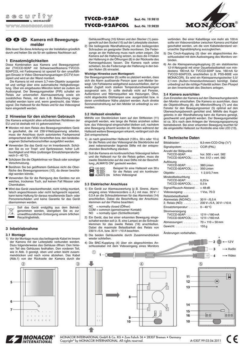
1) Vor derMontage muss dasbeiliegende Kabel imInnern
der Kamera mit der Leiterplatte verbunden werden.
Dazu folgenderweise das Gehäuse öffnen: Den hinte-
ren Teil des Gehäuses festhalten. Den vorderen Teil,
wie in Abb. 3 gezeigt, oben und unten leicht zusam-
mendrücken und nach vorne abziehen. Das Kabel
(Abb.1) von der Rückseite der Kamera durch die
Soll das Gerät endgültig aus dem Betrieb
genommen werden, übergeben Sie es zur
umweltfreundlichen Entsorgung einem örtlichen
Recyclingbetrieb.
Gehäuseöffnung (10) führen und den Stecker (1) pass-
gerechtauf den Sockel(15) aufder Leiterplatte stecken.
2) Die beiliegende Wandhalterung mit den beiliegenden
Schrauben an geeigneter Stelle montieren. Die Feder-
zunge an der Halterung muss nach unten zeigen. Die
Kamera auf die Halterung setzen, so dass die 4 Haken
der Halterung in die Öffnungen (8) in der Rückseite des
Kameragehäuses fassen. Die Kamera nach unten
schieben, bis die Federzunge der Halterung in den bei-
den Nuten (9) einrastet.
Wichtige Hinweise zum Montageort:
Der Bewegungsmelder (5) sollte so platziert werden, dass
sich die Alarm auslösende Person quer zum Melder be-
wegt. Um Fehlalarme weitgehend auszuschließen, darf er
weder Zugluft noch starken Temperaturschwankungen
ausgesetzt sein. Er sollte deshalb nicht auf Fenster,
Außentüren und Wärmequellen wie Heizungen, Öfen,
nicht abgedeckte Glühlampen usw. ausgerichtet bzw. in
deren unmittelbarer Nähe platziert werden. Auch direkte
Sonneneinstrahlung auf den Melder ist unbedingt zu ver-
meiden.
3.2 Haltezeit einstellen
Mithilfe von Steckbrücken kann auf den Stiftleisten (11)
eingestellt werden, wie lange die Relais anziehen sollen
bzw. das Videosignal eingeschaltet bleiben soll, nachdem
eine Bewegung erkannt worden ist. Werden während der
Haltezeitweitere Bewegungen erkannt, verlängertsich die
Zeit entsprechend.
1) Je nach gewünschter Haltezeit (120s, 30s oder 10s)
für die Relais und das Videosignal die Steckbrücke auf
zwei nebeneinander liegende Stifte mit der entspre-
chenden Beschriftung stecken.
2) Soll die Kamera ein kontinuierliches Videosignal liefern
und die Haltezeit nur für die Relais gelten, muss die
zweite Steckbrücke auf die zwei Stifte mit der Beschrif-
tung „ALWAYS ON“ gesteckt werden.
Beispiel für eine Haltezeit von
30s für die Relais und ein kon-
tinuierliches Videosignal
3.3 Elektrischer Anschluss
1) Ein Gerät zur Alarmauswertung (z.B. Sirene, Alarm-
eingang eines Videorecorders o.Ä.) mit max. 30V /
0,5A an die Schraubklemmen für das Alarmrelais (14)
anschließen. Dabei die Beschriftung der Anschluss-
klemmen auf der Platine beachten:
NC = normally closed (Öffner)
COM = common (gemeinsamer Kontakt)
NO = normally open (Schließkontakt)
2) Ein Gerät, das bei einer erkannten Bewegung einge-
schaltet werden soll (z. B. eine Lampe) an die
Schraubklemmen für das zweite Relais (16) an-
schließen. Dabei die maximale Belastbarkeit des
Relais von 230V~/5A, bzw. 30V /10A beachten.
3) Die beiden Gehäuseteile durch Zusammendrücken
wieder schließen.
4) Die BNC-Kupplung (4) über ein abgeschirmtes An-
schlusskabel mit dem Videoeingang eines Monitors
120 SEC
30 SEC
10 SEC
ALWAYS ON
verbinden. Bei einer Kabellänge von mehr als 100m
sollte ein Videoverstärker zwischen Kamera und Kabel
geschaltet werden, um die vom Kabelwiderstand ver-
ursachte Signaldämpfung auszugleichen.
5) Die Cinch-Kupplung (3) über ein abgeschirmtes An-
schlusskabel mit dem Audioeingang des Monitors ver-
binden.
6) An die Kleinspannungskupplung (2) ein stabilisiertes
12-V-Netzgerät mit einer Dauerbelastbarkeit von min-
destens 180mA für TVCCD-92AP bzw. 160mA für
TVCCD-92APCOL anschließen (z.B. PS-500ST von
MONACOR). Es wird ein Kleinspannungsstecker 5,5/
2,1mm (Außen-/Innendurchmesser) benötigt. Dabei
unbedingt auf die richtige Polarität achten: Den Pluspol
an den Innenkontakt des Steckers anlegen.
3.4 Kamera ausrichten
Zum Einstellen der Kamera auf den Überwachungsbereich
den Monitor einschalten. Die Kamera so ausrichten, dass
die Objektivöffnung (6), die Mikrofonöffnung (7) und das
Fenster für den Bewegungssensor (5) optimal auf den
Überwachungsbereich gerichtet sind. Mithilfe des Kugel-
gelenks in der Wandhalterung kann die Kamera geneigt,
geschwenkt und gedreht werden. Der Bewegungsmelder
ist ca. 30s nach dem Anlegen der Versorgungsspannung
betriebsbereit. Bei einer erkannten Bewegung leuchtet für
die eingestellte Haltezeit zur Kontrolle eine rote LED (13).
4Technische Daten
Bildabtaster: . . . . . . . . . . . 8,5-mm-CCD-Chip (1/3")
Signalsystem: . . . . . . . . . . CCIR (PAL)
Anzahl der Bildpunkte
TVCCD-92AP: . . . . . . . hor. 500 ×vert. 582
TVCCD-92APCOL:. . . . hor. 512 ×vert. 582
Auflösung
TVCCD-92AP: . . . . . . . 380Linien
TVCCD-92APCOL:. . . . 350Linien
Objektiv: . . . . . . . . . . . . . . 1:2,0/3,7mm
Mindestbeleuchtung
TVCCD-92AP: . . . . . . . 0,25lx
TVCCD-92APCOL:. . . . 0,5lx
Signal/Rausch-Abstand:. . > 48dB
Videoausgang: . . . . . . . . . 1Vss, 75Ω
Relaisbelastbarkeit
Alarmrelais (NO/NC): . . . . 30V /0,5A
2. Relais (NO): . . . . . . . . . 230V~/5A, 30V /10A
Einsatztemperatur: . . . . . . 0–40°C
Stromversorgung
TVCCD-92AP: . . . . . . . 12V /180mA
TVCCD-92APCOL:. . . . 12V /160mA
Abmessungen: . . . . . . . . . 70 ×110 ×50mm
Gewicht: . . . . . . . . . . . . . . 155g
Änderungen vorbehalten.
®
TVCCD-92AP
TVCCD-92APCOL
Best.-Nr. 19.9810
Best.-Nr. 19.9820
Copyright©by MONACOR INTERNATIONAL GmbH & Co. KG, Bremen, Germany. All rights reserved. A-0307.99.02.02.2007
®
5
6
7
8
9
10
11
12
13
14
15
16
10
Video
+
-
12V
Audio
1
2
3
4
➁➃➄
➀
➂
D A CH

Camera with Motion Detector
Please read these operating instructions carefully prior to
the installation and keep them for later use.
1Applications
This combination of camera and motion detector (TVCCD-
92AP with black-and-white camera/TVCCD-92APCOL
with colour camera) is especially designed for the incon-
spicuous use in video surveillance systems (CCTV) and is
mounted to the wall.
The camera is equipped with a 3.7mm lens and has an
automatic brightness control. Via an installed microphone
it additionally supplies an audio signal. The motion detec-
tor (PIR) switches a relay for universal alarm evaluation
and an additional relay to switch on e.g. the illumination
and, if desired, the video signal. The holding time for the
relays and for the video signal can be adjusted.
2Safety Notes
The camera corresponds to all required directives of the
EU and is therefore marked with .
●If units operating with 230V mains voltage are switched
with the relay of the motion detector, the connection
must be made by authorized, specialized personnel
according to the German VDE regulations (German
safety regulations) or the safety regulations for the re-
spective country.
●The unit is suitable for indoor use only. Protect it against
dripping water and splash water, high air humidity, and
heat (admissible ambient temperature range 0–40°C).
●Protect the lens against dust and other impurities.
●Do not touch the surface of the motion sensor (12) with
the housing opened, as the sensor may be damaged.
●For cleaning only use a dry, soft cloth, by no means
chemicals or water.
●No guarantee claims for the unit and no liability for any
resulting personal damage or material damage will be
accepted if the camera is used for other purposes than
originally intended, if it is not correctly mounted, con-
nected, or not repaired in an expert way.
3Setting into Operation
3.1 Mounting
1) Prior to mounting, the supplied cable must be con-
nected to the PCB inside the camera. For this purpose
open the housing as follows: Hold the rear part of the
housing. Slightly press together the front part at the top
and bottom as shown in fig. 3 and remove it forwards.
Guide the cable (fig. 1) from the rear side of the cam-
era through the housing opening (10) and place the
If the unit is to be put out of operation definitively,
take it to a local recycling plant for a disposal
which is not harmful to the environment.
plug (1) on the connector (15) of the PCB so that it fits
precisely.
2) Mount the supplied wall support with the supplied
screws to a suitable place. The latch at the bracket
must show downwards. Place the camera on the
bracket so that the 4 hooks of the bracket catch in the
openings (8) in the rear side of the camera housing.
Slide the camera downwards until the latch of the
bracket engages in the two grooves (9).
Important notes on the place of mounting:
The motion detector (5) should be placed in such a way
that the person triggering an alarm diagonally moves to the
detector. To prevent false alarms to a large extent, it must
neither be exposed to draught nor strong temperature
variations. Therefore, it should not be directed towards
windows, outside doors, and heat sources like heatings,
ovens, uncovered incandescent lamps, etc. or be placed in
their immediate surroundings. Also, the detector must not
be exposed to direct sun radiation in any case.
3.2 Adjusting the holding time
By means of jumpers it is possible to adjust on the pin
connectors (11) how long the relays are to respond or the
video signal is to remain switched on after a movement
has been detected. If further movements are detected
during the holding time, the time is extended accordingly.
1) Depending on the desired holding time (120s, 30s, or
10s) for the relays and the video signal, place the jum-
per on two adjacent pins with the corresponding letter-
ing.
2) If the camera is to supply a continuous video signal and
the holding time is only to be valid for the relays, the
second jumper must be placed on the two pins with the
lettering “ALWAYS ON”.
Example for a holding time of
30s for the relays and a con-
tinuous video signal
3.3 Electrical connection
1) Connect a unit for alarm evaluation (e.g. siren, alarm
input of a video recorder, or similar unit) with max.
30V /0.5A to the screw terminals for the alarm relay
(14). Observe the lettering of the connecting terminals
on the PCB:
NC = normally closed (opening contact)
COM = common (common contact)
NO = normally open (closing contact)
2) Connect a unit to be switched on with detected move-
ment (e.g. a light) to the screw terminals for the second
relay (16). Observe the maximum rating of the relay of
230V~/5 A or 30 V /10A.
3) Close the two housing parts by pressing them together.
4) Connect the BNC inline jack (4) via a screened cable to
the video input of a monitor. With a cable length of
more than 100m, a video amplifier should be inserted
120 SEC
30 SEC
10 SEC
ALWAYS ON
between the camera and the cable to compensate the
signal attenuation caused by the cable resistance.
5) Connect the phono inline jack (3) via a screened cable
to the audio input of the monitor.
6) Connect a regulated 12V power supply unit with a per-
manent rating of at least 180mA for TVCCD-92AP or
160mA for TVCCD-92APCOL (e.g. PS-500ST from
MONACOR) to the low-voltage inline jack (2). A low-
voltage plug 5.5/2.1mm (outside/inside diameter) is
required. Observe in any case the correct polarity:
Apply the positive pole to the inside contact of the plug.
3.4 Adjusting the camera
Switch on the monitor for adjusting the camera to the sur-
veillance zone.Adjust the camera so that the lens aperture
(6), the microphone aperture (7), and the window for the
motion sensor (5) are directed to the surveillance zone in
an optimum way. By means of the ball joint in the wall
bracket the camera can be tilted, panned, and turned. The
motion detector is ready for operation approx. 30s after
applying the supply voltage. With a detected movement a
red indicating LED (13) lights up for the adjusted holding
time.
4Specifications
Image sensor: . . . . . . . . . . 8.5mm (1/3") CCD chip
Signal system:. . . . . . . . . . CCIR (PAL)
Number of pixels
TVCCD-92AP: . . . . . . . hor. 500 ×vert. 582
TVCCD-92APCOL:. . . . hor. 512 ×vert. 582
Resolution
TVCCD-92AP: . . . . . . . 380 lines
TVCCD-92APCOL:. . . . 350 lines
Lens: . . . . . . . . . . . . . . . . . 1:2.0/3.7mm
Minimum illumination
TVCCD-92AP: . . . . . . . 0.25lx
TVCCD-92APCOL:. . . . 0,5lx
S/N ratio:. . . . . . . . . . . . . . > 48dB
Video output:. . . . . . . . . . . 1Vpp, 75Ω
Rating of the relays
alarm relay (NO/NC): . . 30V /0.5A
2nd relay (NO):. . . . . . . 230V~/5A, 30V /10A
Ambient temperature: . . . . 0–40°C
Power supply
TVCCD-92AP: . . . . . . . 12V /180mA
TVCCD-92APCOL:. . . . 12V /160mA
Dimensions: . . . . . . . . . . . 70 ×110 ×50mm
Weight: . . . . . . . . . . . . . . . 155g
Subject to technical modification.
®
TVCCD-92AP
TVCCD-92APCOL
Order No. 19.9810
Order No. 19.9820
Copyright©by MONACOR INTERNATIONAL GmbH & Co. KG, Bremen, Germany. All rights reserved. A-0307.99.02.02.2007
®
5
6
7
8
9
10
11
12
13
14
15
16
10
Video
+
-
12V
Audio
1
2
3
4
➁➃➄
➀
➂
GB

Caméra avec détecteur
de mouvements
Veuillez lire la présente notice avec attention avant l’in-
stallation et conservez-la pour pouvoir vous y reporter
ultérieurement.
1Possibilités d’utilisation
Cette combinaison d’une caméra et d’un détecteur de
mouvements (TVCCD-92AP avec caméra noir et blanc/
TVCCD-92APCOLaveccaméra couleur) estspécialement
conçue pour une utilisation discrète dans des installations
de vidéosurveillance (CCTV) et se monte sur le mur.
La caméra est dotée d’un objectif 3,7mm et dispose
d’un réglage automatique de luminosité. Via un micro-
phone intégré, elle délivre en plus un signal audio. Le
détecteur de mouvements (PIR) commute un relais pour
une évaluation universelle d’alarme et un relais supplé-
mentaire avec lequel par exemple un éclairage peut être
allumé et si souhaité le signal vidéo. La durée de maintien
pour les relais et pour le signal vidéo est réglable.
2Conseils d’utilisation et de sécurité
La caméra répond à toutes les directives nécessaires de
l’Union Européenne et porte donc le symbole .
●Si des appareils fonctionnant avec une alimentation en
230V~sont branchésaveclerelaisdu détecteurde mou-
vements, seul un personnel spécialisé et habilité peut
effectuerle branchementconformément auxréglementa-
tions VDE (réglementations allemandes de sécurité) ou
aux réglementations de sécurité pour le pays concerné.
●N’utilisez l’appareil que pour une utilisation en intérieur.
Protégez-les de tout type de projections d’eau, des écla-
boussures,d’une humidité élevéeet lachaleur(plage de
température de fonctionnement autorisée : 0–40°C).
●Protégez la lentille de l’objectif de la poussière et autre
salissure.
●Ne touchez pas la surface du détecteur de mouvements
(12) lorsque le boîtier est ouvert, il pourrait être endom-
magé.
●Pourle nettoyage,utilisezuniquement avecunchiffonsec
et doux, en aucun cas de produits chimiques ou d’eau.
●Nous déclinons toute responsabilité en cas de domma-
ges corporels ou matériels résultants si l’appareil est uti-
lisé dans un but autre que celui pour lequel il a été
conçu, s’il n’est pas correctement monté, branché ou
réparé par une personne habilitée ; de même, la garan-
tie deviendrait caduque.
3Fonctionnement
3.1 Montage
1) Avant le montage, le câble livré doit être relié au circuit
imprimé à l’intérieur de la caméra. Pour ce faire, ouvrez
le boîtier comme suit : maintenez la partie arrière du
boîtier. Pressezdoucement la partieavant enhaut et en
bas comme montré sur le schéma 3, puis retirez-la vers
Lorsque l’appareil est définitivement retiré du
service, vous devez le déposer dans une usine
de recyclage de proximité pour contribuer à son
élimination non polluante.
l’avant. Faites passer le câble (schéma 1) de la face
arrière de la caméra via l’ouverture (10) dans le boîtier
et reliez la fiche (1) sur le connecteur (15) sur le circuit
imprimé de manière à ce qu’il s’encastre correctement.
2) Montezle support muralfourni avec lesvis livrées àl’en-
droit voulu. La languette sur le support doit être dirigée
versle bas.Mettez lacaméra surle supportde sorteque
les 4 crochets du support s’encastrent dans les ouvertu-
res (8) sur la face arrière du boîtier de la caméra. Pous-
sez la caméra vers le bas jusqu’à ce que la languette du
support s’encastre dans les deux encoches (9).
Conseils importants pour le lieu de montage :
Le détecteur de mouvements (5) devrait être placé de
sorte que la personne déclenchant l’alarme se déplace en
diagonale par rapport au détecteur. Pour exclure au maxi-
mum toute fausse alarme, il ne doit pas être placé dans
des courants d’air ou soumis à des fluctuations importan-
tes de température. C’est pourquoi, il est recommandé de
ne pas le diriger vers des fenêtres, portes extérieures,
sources de chaleur comme chauffages, fours, lampes à
incandescence non couvertes etc, ou le placer à leur pro-
ximité immédiate. De même un rayonnement direct du
soleil sur le détecteur est à éviter dans tous les cas.
3.2 Réglage de la durée de maintien
Al’aide de cavaliers, on peut régler sur les connecteurs
(11) combien de temps les relais doivent répondre ou le
signal vidéo doit rester allumé après la détection d’un
mouvement. Si pendant la durée de maintien d’autres
mouvements sont détectés, la durée se rallonge en
conséquence :
1) Selon la durée souhaitée (120s, 30s ou 10s) pour les
relais ou le signal vidéo, mettez le cavalier sur deux
pins côte à côte avec le repérage correspondant.
2) Si la caméra doit délivrer un signal vidéo continu et si
la durée de maintien ne vaut que pour les relais, le
second cavalier doit être mis sur les deux pins avec le
repérage “ALWAYS ON”.
Exemple pour une durée de
maintien de 30 secondes pour
les relais et un signal vidéo con-
tinu
3.3 Branchement électrique
1) Reliez un appareil pour l’évaluation d’alarme (p.ex.
sirène, entrée d’alarme d’un magnétoscope …) avec
30V /0,5A maximum aux bornes à vis pour le relais
d’alarme (14). Respectez le repérage des bornes de
branchement sur la platine :
NC = normally closed (contact d’ouverture)
COM = common (contact commun)
NO = normally open (contact de fermeture)
2) Connectez un appareil qui doit être allumé lorsqu’un
mouvement est détecté (p.ex. une lampe) aux bornes
à vis pour le second relais (16). Respectez la charge
maximale du relais de 230V~/5 Aou 30V /10A.
3) Refermez les deux éléments du boîtier en les poussant
ensemble.
4) Reliez la fiche BNC femelle (4) via un cordon de bran-
chement blindé à l’entrée vidéo d’un moniteur. Pour
120 SEC
30 SEC
10 SEC
ALWAYS ON
une longueur de câble supérieure à 100m, il est
recommandé d’installer un amplificateur vidéo entre la
caméra et le câble pour compenser l’atténuation du
signal causée par la résistance du câble.
5) Reliez la fiche RCA (3) via un cordon audio blindé à
l’entrée audio du moniteur.
6) Connectezun bloc secteurstabilisé 12Vavec une char-
gepermanente de180mAaumoins pourTVCCD-92AP
ou160 mApour TVCCD-92APCOL(p.ex. PS-500STde
MONACOR) à la fiche d’alimentation (2). Un adaptateur
5,5/2,1mm (diamètre extérieur/intérieur) est nécessai-
re. Veillez à respecter la polarité : le pôle plus doit être
au contact intérieur de la fiche.
3.4 Orientation de la caméra
Pour régler la caméra sur la zone de surveillance, allumez
le moniteur. Dirigez la caméra de sorte que l’ouverture de
l’objectif (6), l’ouverture du micro (7) et la fenêtre pour le
détecteur de mouvements (5) soient orientés de manière
optimale vers la zone de surveillance. A l’aide de l’articu-
lation à rotule dans le support mural, il est possible d’incli-
ner la caméra vers le haut et le bas et de l’orienter de droi-
te à gauche. Le détecteur de mouvements est prêt à fonc-
tionner 30 secondes environ après l’application de la ten-
sion d’alimentation. En cas de détection d’un mouvement,
une LED rouge (13) brille comme contrôle pour la durée
de maintien réglée.
4Caractéristiques techniques
Puce : . . . . . . . . . . . . . . . . CCD 8,5mm (1/3")
Système signal : . . . . . . . . CCIR (PAL)
Nombre de points
TVCCD-92AP : . . . . . . . hor. 500 ×vert. 582
TVCCD-92APCOL : . . . hor. 512 ×vert. 582
Résolution
TVCCD-92AP : . . . . . . . 380lignes
TVCCD-92APCOL : . . . 350lignes
Objectif : . . . . . . . . . . . . . . 1:2,0/3,7mm
Luminosité minimale
TVCCD-92AP : . . . . . . . 0,25 lux
TVCCD-92APCOL : . . . 0,5lux
Rapport signal/bruit : . . . . > 48dB
Sortie vidéo :. . . . . . . . . . . 1Vcc, 75Ω
Puissance relais
Relais d’alarme (NO/NC) : 30V /0,5A
2. relais (NO) :. . . . . . . . . . 230V~/5A, 30 V /10A
Température fonc. : . . . . . . 0–40°C
Alimentation
TVCCD-92AP : . . . . . . . 12V /180mA
TVCCD-92APCOL : . . . 12V /160mA
Dimensions : . . . . . . . . . . . 70 ×110 ×50mm
Poids :. . . . . . . . . . . . . . . . 155 g
Tout droit de modification réservé.
®
TVCCD-92AP
TVCCD-92APCOL
Ref. num. 19.9810
Ref. num. 19.9820
Copyright©by MONACOR INTERNATIONAL GmbH & Co. KG, Bremen, Germany. All rights reserved. A-0307.99.02.02.2007
®
5
6
7
8
9
10
11
12
13
14
15
16
10
Video
+
-
12V
Audio
1
2
3
4
➁➃➄
➀
➂
FBCH

Telecamera con segnalatore di
movimento
Vi preghiamo di leggere attentamente le presenti istruzioni
prima dell’installazione e di conservarle per un uso futuro.
1Possibilità di impiego
Questa combinazione fra telecamera e segnalatore di mo-
vimento (TVCCD-92AP con telecamera b/n, TVCCD-
92APCOLcontelecamera acolori) è statarealizzata speci-
almente per l’impiego non vistoso in impianti di sorveglian-
za video (CCTV) ed è prevista per il montaggio a parete.
La telecamera è equipaggiata con un obiettivo di
3,7mm e dispone di regolazione automatica della lumino-
sità. Grazie al microfono integrato è in grado di fornire
anche un segnale audio. Il segnalatore di movimento (PIR)
attiva un relè per l’elaborazione universale di un allarme, e
unrelè supplementarecon cui sipuò, p.es.,accendere una
luce e, si desirate, il segnale video. La durata del relè e del
segnale video può essere impostata secondo necessità.
2Avvertenze di sicurezza
La telecamera è conforme a tutte le direttive richieste
dell’UE e pertanto porta la sigla .
●Se con il relè del segnalatore di movimento si attivano
degli apparecchi che funzionano con tensione di rete di
230V, il collegamento deve essere fatto da personale
specializzato autorizzato e secondo la normativa VDE o
secondo le norme di sicurezza del relativo paese.
●Far funzionare l’apparecchio solo all’interno di locali.
Proteggerlo dall’acqua gocciolante e dagli spruzzi d’ac-
qua, da alta umidità dell’aria e dal calore (temperatura
d’impiego ammessa fra 0 e 40°C).
●Proteggere la lente dell’obiettivo dalla polvere e dallo
sporco in genere.
●Se il contenitore è aperto non toccare la superficie del
sensore di movimento (12) per non danneggiarlo.
●Per la pulizia usare solo un panno morbido, asciutto;
non impiegare in nessun caso prodotti chimici o acqua.
●Nel caso d’uso improprio, di montaggio errato, di colle-
gamenti sbagliati o di riparazione non a regola d’arte
dell’apparecchio, non si assume nessuna responsabilità
per eventuali danni consequenziali a persone o a cose
e non si assume nessuna garanzia per lo strumento.
3Messa in funzione
3.1 Montaggio
1) Prima del montaggio occorre collegare il cavo in dota-
zione con il circuito stampato all’interno della teleca-
mera. Per fare ciò aprire il contenitore: tenere ferma la
parte posteriore del contenitore. Esercitare una legge-
ra pressione sulla parte anteriore, come da fig. 3, e
precisamente sotto e sopra e sfilare la parte anteriore
verso il davanti. Fare passare il cavo (fig.1) dal retro
della telecamera attraverso il passacavo del contenito-
Se si desidera eliminare l’apparecchio definitiva-
mente, consegnarlo per lo smaltimento ad un’i-
stituzione locale per il riciclaggio.
re (10) e inserire il connettore (1) nello zoccolo (15) del
circuito stampato.
2) Montare il supporto da parete in un posto adatto, ser-
vendosi delle viti in dotazione. La linguetta del suppor-
to deve essere rivolta verso il basso. Inserire la teleca-
mera nel supporto in modo tale che i 4 ganci del sup-
porto entrino nelle aperture (8) sul retro della teleca-
mera. Spingere la telecamera verso il basso finché la
linguetta del supporto entra a scatto nelle due scanala-
ture (9).
Note importanti sul luogo di montaggio:
Il segnalatore di movimento (5) dovrebbe essere posizio-
nato in modo tale che la persona che fa scattare l’allarme
si muove in direzione trasversale rispetto al segnalatore.
Per escludere il più possibile falsi allarmi, il segnalatore
non deve essere esposto né a correnti d’aria né a forti
cambi di temperatura. Pertanto non dovrebbe essere
orientato verso finestre, porte verso l’esterno e sorgenti di
calore come termosifoni o stufe, lampadine non coperte
ecc., e non dovrebbe essere posizionato nella loro diretta
vicinanza. Anche i raggi diretti del sole sul segnalatore
sono da evitare.
3.2 Impostare la durata
Con l’aiuto dei ponticelli sui connettori maschio (11) si può
impostare la durata per la reazione del relè o per il segna-
le video dopo il rilevamento di un movimento. Se durante
tale periodo si rilevano altri movimenti, il tempo aumenta
in corrispondenza.
1) Aseconda della durata richiesta (120s, 30s o 10s) per
i relè e il segnale video, inserire il ponticello su due pin
vicini seguendo le indicazioni scritte.
2) Se la telecamera deve fornire un segnale video conti-
nuo mentre la durata riguarda solo i relè, il secondo
ponticello deve essere posizionato sui due pin con la
scritta ”ALWAYS ON”.
Esempio per la durata di 30s
per i relè e per il segnale video
continuo
3.3 Collegamento elettrico
1) Collegare un apparecchio per l’elaborazione dell’allar-
me (p.es. sirena, ingresso d’allarme di un videoregi-
stratore o simili.) con max. 30V /0,5A con i morsetti
a vite (14) del relè d’allarme, rispettando la scritta rela-
tiva ai morsetti sul circuito stampato:
NC = normally closed (contatto NC)
COM = common (contatto comune)
NO = normally open (contatto NA)
2) Collegare un apparecchio che deve essere attivato nel
casodiun movimento rilevato(p. es. unalampada) con
i morsetti a vite (16) per il secondo relè tenendo conto
della potenza massima del relè di 230V~/5A opp.
30V /10A.
3) Chiudere le due parti del contenitore spingendole l’una
contro l’altra.
4) Collegare la presa BNC (4) con l’ingresso video di un
monitor servendosi di un cavo schermato di collega-
mento. Nel caso di un cavo di oltre 100m di lunghezza,
120 SEC
30 SEC
10 SEC
ALWAYS ON
conviene inserire un amplificatore video fra telecamera
e cavo per compensare l’attenuazione del segnale
causata dalla resistenza del cavo.
5) Collegare la presa RCA (3) con l’ingresso audio del
monitor per mezzo di un cavo schermato di collega-
mento.
6) Alla presa per alimentazione DC (2) si deve collegare
un alimentatore stabilizzato per 12V con potenza
permanentedi180mAmin. perTVCCD-92APopurre di
160mA min. per TVCCD-92APCOL (p.es. PS-500ST
di MONACOR). È richiesto uno spinotto di 5,5/2,1mm
(diametro esterno/interno). Fare assolutamente atten-
zione alla corretta polarità: il polo positivo deve essere
collegato con il contatto interno del connettore.
3.4 Orientare la telecamera
Per regolare la telecamera rispetto alla zona da sorve-
gliare accendere il monitor. Orientare la telecamera in
modo tale che l’apertura per l’obiettivo (6), l’apertura per il
microfono (7) e la finestra per il sensore di movimento (5)
siano orientati in modo ottimale sulla zona da sorvegliare.
Con l’aiuto del giunto sferico nel supporto a parete, la tel-
ecamera può essere inclinata, basculata e girata. Il seg-
nalatore di movimento è pronto per l’uso ca. 30s dopo che
è stata applicata la tensione di alimentazione. Se viene
riconosciuto un movimento, un LED rosso (13) rimane
acceso per controllo per tutta la durata impostata.
4Dati tecnici
Sensore ottico: . . . . . . . . . chip CCD 8,5mm (1/3")
Sistema di segnale video:. CCIR (PAL)
Numero pixel
TVCCD-92AP: . . . . . . . orizz. 500 ×vert. 582
TVCCD-92APCOL:. . . . orizz. 512 ×vert. 582
Risoluzione
TVCCD-92AP: . . . . . . . 380 linee
TVCCD-92APCOL:. . . . 350 linee
Obiettivo:. . . . . . . . . . . . . . 1:2,0/3,7mm
Illuminazione minima
TVCCD-92AP: . . . . . . . 0,25 lx
TVCCD-92APCOL:. . . . 0,5 lx
Rapporto S/R:. . . . . . . . . . > 48dB
Uscita video: . . . . . . . . . . . 1Vpp, 75Ω
Potenza relè
Relè d’allarme (NO/NC):. . 30V /0,5A
2. relè (NO): . . . . . . . . . . . 230V~/5 A, 30V /10A
Temperatura d’esercizio:. . 0–40°C
Alimentazione:
TVCCD-92AP: . . . . . . . 12V /180mA
TVCCD-92APCOL:. . . . 12V /160mA
Dimensioni: . . . . . . . . . . . . 70 ×110 ×50mm
Peso:. . . . . . . . . . . . . . . . . 155g
Con riserva di modifiche tecniche.
®
TVCCD-92AP
TVCCD-92APCOL
N. articolo 19.9810
N. articolo 19.9820
Copyright©by MONACOR INTERNATIONAL GmbH & Co. KG, Bremen, Germany. All rights reserved. A-0307.99.02.02.2007
®
5
6
7
8
9
10
11
12
13
14
15
16
10
Video
+
-
12V
Audio
1
2
3
4
➁➃➄
➀
➂
I

Cámara con detector de movi-
ientos
Por favor, lea atentamente estas instrucciones antes de la
instalación y consérvelas para usos posteriores.
1Aplicaciones
Esta combinación de cámara y detector de movimien-
tos (TVCCD-92AP con cámara blanco-negro/TVCCD-
92APCOL con cámara color) está especialmente diseña-
da para el uso discreto en sistemas de vigilancia vídeo
(CCTV) y se monta en la pared.
La cámara está equipada con una lente de 3,7mm y
tiene un control automático de brillo. Vía un micrófono
instalado proporciona adicionalmente una señal audio. El
detector de movimiento (PIR) conecta un relé para la eva-
luación de la alarma universal y un relé adicional para
poder conectar por ejemplo, la iluminación y, si se desea,
la señal vídeo. El tiempo de funcionamiento para los relés
y para la señal vídeo puede ajustarse.
2Consejos de utilización
La cámara corresponde a todas las directivas requeridas
por la UE y por ello está marcada con .
●Siunidadesque funcionan convoltaje principal de230V
se conectan con el relé del detector de movimientos, la
conexión debe llevarse a cabo por personal autorizado,
especializado según las normas de seguridad alemana
VDE o las normas de seguridad del país respectivo.
●La cámara está concebida sólo para una utilización en
interior. Protegerla de todo tyipo de proyecciones de
agua, de las salpicaduras, de la humedad elevado y del
calor (rango de temperaturas de funcionamiento auto-
rizado 0–40°C).
●Proteger la lente del polvo y otras impurezas.
●Nunca tocar la superficie del sensor de movimientos (12)
con la carcasa abierta, ya que el sensor podría dañarse.
●Para limpiar el aparato, utilizar un paño seco y blando,
en ningún caso, productos químicos o agua.
●Declinamos cualquier responsabilidad en caso de
daños materiales o corporales resultandos si la cámara
se utiliza para otro fin que no sea el que ha sido conce-
bida, si no se monta o conecta correctamente o si no es
reparada por una persona cualificada; por estos mis-
mos motivos carecería todo tipo de garantía.
3Funcionamiento
3.1 Montaje
1) Antes de montarla, el cable proporcionado debe
conectarse al PCB de dentro de la cámara. Para este
propósito, abrir la carcasa de la siguiente manera:
sujetar la parte trasera de la carcasa. Suavemente pre-
sionar la parte frontal de arriba y abajo como se mue-
stra en la fig. 3 y sacarla hacia delante. Dirigir el cable
(fig. 1) de la parte trasera de la cámara a través de la
apertura de la carcasa (10) y colocar la toma (1) en el
Cuando se retira definitivamente la cámara del
servicio, debe depositarse en una fábrica de
reciclaje adaptada para su eliminación no con-
taminante.
conector (15) de la PCB de manera que encaje de
forma precisa.
2) Montar la abrazadera de pared proporcionada con los
tornillos proporcionados en el lugar adecuado. El cie-
rre de la abrazadera debe estar hacia abajo. Colocar la
cámara encima de la abrazadera de manera que los 4
ganchos de la abrazadera encajen en las aperturas (8)
de la parte trasera de la carcasa de la cámara. Deslizar
la cámara hacia abajo hasta que el cierre de la abra-
zadera encaje en los dos surcos (9)
Notas importantes sobre el lugar de montaje:
El detector de movimientos (5) debería colocarse de ma-
nera que la persona accionando la alarma se mueva dia-
gonalmente hacia esto. Para prevenir falsas alarmas lo
mejor posible, no debe someterse el detector ni a la co-
rriente de aire ni a variaciones fuertes de temperatura. Por
eso, no debería encararse directamente a ventanas, puer-
tas exteriores y fuentes de calor como calefacciones, hor-
nos, lámparas incandescentes descubiertos, etc. o en su
proximidad inmediata. El detector de movimientos no
debe exponerse directamente a la radiación solar en
ningún caso.
3.2 Ajustando el tiempo de funcionamiento
Mediante las grapas puede ajustarse en los conectores
pin (11) el tiempo de funcionamiento durante el cual los
relés deben responder o la señal vídeo debe permanecer
conectada una vez se ha detectado un movimiento. Si se
detectan más movimientos durante el tiempo de funcio-
namiento, el tiempo se alarga respectivamente.
1) Según el tiempo deseado de funcionamiento (120s,
30s, o 10s) para los relés y la señal vídeo, colocar la
grapa sobre dos pins adyacentes con la inscripción
correspondiente.
2) Si la cámara debe llevar a cabo una señal de vídeo
continua y el tiempo de funcionamiento debe sólo ser
válido para los relés, el segunda grapa debe colocarse
sobre los dos pins con la inscripción “ALWAYS ON”.
Ejemplo para un tiempo de fun-
cionamiento de 30s para los re-
lés y una señal de vídeo conti-
nua
3.3 Conexión eléctrica
1) Conectar una unidad para la evaluación de la alarma
(p.ej., sirena, entrada de alarma de un grabador vídeo
o una unidad similar) con máx. 30V /0,5A en las ter-
minales atornilladas para el relé de la alarma (14).
Observar la inscripción de las terminales de conexión
en el PCB:
NC = normalmente cerrado (contacto que abre)
COM = común (contaco común)
NO = normalmente abierto (contacto que cierre)
2) Conectar una unidad que debe conectarse con un
movimiento detectado (p.ej., una luz) a las terminales
de tornillo para el segundo relé (16). Observar la capa-
cidad máxima del relé de 230V~/5A o 30V /10A.
3) Cerrar las dos partes de la carcasa presionándolas a la
vez.
120 SEC
30 SEC
10 SEC
ALWAYS ON
®
TVCCD-92AP
TVCCD-92APCOL
Ref. num. 19.9810
Ref. num. 19.9820
Copyright©by MONACOR INTERNATIONAL GmbH & Co. KG, Bremen, Germany. All rights reserved. A-0307.99.02.02.2007
®
5
6
7
8
9
10
11
12
13
14
15
16
10
Video
+
-
12V
Audio
1
2
3
4
➁➃➄
➀
➂
E4) Conectar la toma de línea BNC (4) vía un cable blinda-
do a la entrada vídeo del monitor. Con una longitud de
cable superior a 100m un amplificador vídeo debería
instalarse entre la cámara y el cable para compensar
laatenuaciónde la señalcausada por laresistencia del
cable.
5) Conectar la toma phono de línea (3) vía un cable blin-
dado a la entrada audio del monitor.
6) Conectar una unidad de alimentación regulada de 12V
con una capacidad permanente de al menos 180mA
para TVCCD-92AP o 160mA para TVCCD-92APCOL
(por ejemplo, PS-500ST de MONACOR) a la toma de
bajo voltaje (2). Se necesita una toma de bajo voltaje
5,5/2,1mm (diámetro exterior/interior). Observar en
cualquier caso la polaridad correcta: colocar el polo
positivo al contacto interior de la toma.
3.3 Ajustes de cámara
Conectar el monitor para ajustar la cámara a la zona de
vigilancia.Ajustar la cámara de manera que la apertura de
la lente (6), la apertura de micrófono (7), y la ventana para
el sensor de movimientos (5) se dirijan a la zona de vigi-
lancia de manera óptima. Mediante la junta de bola de la
abrazadera de pared, la cámara puede girarse, desplazar-
se horizontalmente y verticalmente. El detector de movi-
mientos está listo para funcionar aproximadamente 30 seg
después de proporcionar el voltaje de alimentación. Con
un movimiento detectado, el LED (13) rojo indicador se
ilumina para el tiempo de funcionamiento ajustado.
4Especificaciones
Sensor de imagen: . . . . . . 8,5mm (1/3") CCD chip
Sistema señal:. . . . . . . . . . CCIR (PAL)
Número de píxels
TVCCD-92AP: . . . . . . . hor. 500 ×vert. 582
TVCCD-92APCOL:. . . . hor. 512 ×vert. 582
Resolución
TVCCD-92AP: . . . . . . . 380líneas
TVCCD-92APCOL:. . . . 350líneas
Lente: . . . . . . . . . . . . . . . . 1:2,0/3,7mm
Iluminación mín
TVCCD-92AP: . . . . . . . 0,25lx
TVCCD-92APCOL:. . . . 0,5lx
Relación señal/ruido: . . . . > 48dB
Salida vídeo: . . . . . . . . . . . 1Vpp, 75Ω
Capacidad de relé
Relé de alarma (NO/NC):30V /0,5A
2do relé (NO):. . . . . . . . 230V~/5 A, 30V /10A
Temperatura ambiente: . . . 0–40°C
Alimentación
TVCCD-92AP: . . . . . . . 12V /180mA
TVCCD-92APCOL:. . . . 12V /160mA
Dimensiones: . . . . . . . . . . 70 ×110 ×50mm
Peso:. . . . . . . . . . . . . . . . . 155g
Sujeto a modificaciones técnicas.

Kamera z czujką ruchu
Prosimy o uważne przeczytanie poniższej instrukcji przed
użyciem urządzenia oraz o zachowanie tekstu do wglądu.
1Zastosowanie
Urządzenie kombinacja kamery i czujnika ruchu (TVCCD-
92Ap – kamera czarno-biała, TVCCD-92APCOL – kame-
ra kolorowa) zostało specjalnie zaprojektowane do użytku
w systemach monitoringu. Jest montowane do ściany.
Kamera jest wyposażona w obiektyw 3,7 mm, posiada
automatyczną regulację jasności, oraz wbudowany
mikrofon do transmisji sygnału audio. Detektor ruchu
(PIR) przełącza przekaźnik sterujący pracą urządzenia
alarmowego oraz dodatkowym przekaźnikiem włącza-
jącym np. oświetlenie oraz jeśli to konieczne sygnał
wideo. Detektor posiada możliwość ustawiania czasu
zadziałania.
2Środki ostrożności
Ponieważ urządzenie spełnia wszelkie normy obowiązują-
ce w Unii Europejskiej, zostało oznaczone symbolem .
●Jeżeli urządzenie sterowane przez przekaźnik czujki
ruchu będzie zasilane napięciem zmiennym 230 V,
podłaczeń może dokonywać jedynie wykwalifikowany
personel.
●Kamera jest przeznaczona tylko do użytku wewnątrz
pomieszczeń. Urządzenie należy chronić przed wilgo-
cią i wysoką temperaturą (dopuszczalny zakres tem-
peratury to 0 – 40 °C).
●Chronić obiektyw przed kurzem oraz innymi zanieczy-
szczeniami.
●Nie dotykać powierzchni czujki ruchu (12) przy otwartej
obudowie, może to spowodować uszkodzenie czujki.
●Do czyszczenia obudowy używać suchej, miękkiej
ściereczki. Nie stosować wody ani środków czysz-
czących.
●Producent ani dostawca nie ponosi odpowiedzialności
za wynikłe szkody materialne, jeśli urządzenie było
używane niezgodnie z przeznaczeniem, zostało zain-
stalowane lub obsługiwane niepoprawnie lub podda-
wane nieautoryzowanym naprawom.
3Przygotowanie do pracy
3.1 Montaż
1) Przed zamontowaniem kamery należy podpiąć do
płytki PCB załączony przewód. W tym celu należy
otworzyć obudowę: Przytrzymać tylną część obudo-
wy. Lekko ścisnąć przednią część obudowy jak poka-
zano na rysunku 3 a następnie zdjąć ją. Wprowadzić
przewód pokazany na rys. 1 od tyłu obudowy przez
Jeśli urządzenie nie będzie już nigdy więcej
używane, wskazane jest przekazanie go do
miejsca utylizacji odpadów, aby zostało utylizo-
wane bez szkody dla środowiska.
otwór (10) i wetknąć wtyk (1) do gniazda (15).
Następnie zamknąć obudowę.
2) Zamocować dołączony uchwyt ścienny w wyma-
ganym miejscu. Zatrzask na uchwycie powinien być
skierowany w dół. Umieścić kamerę na uchwycie aby
4 zatrzaski weszły w otwory montażowe (8) znajdują-
ce się z tyłu obudowy. Pociągnąć w dół kamerę
dopóki zatrzaski uchwytu nie znajdą się w dwóch row-
kach (9).
Wskazówki odnośne miejsca montażu urządzenia:
Czujka ruchu (5) powinna być zamontowana w ten
sposób, aby osoba mająca wywołać alarm poruszała się
po przekątnej w stosunku do czujki. Aby uniknąć fałszy-
wego alarmu, czujka nie może być montowana w miejsc-
ach gdzie występują ciągi powietrza oraz duże wahania
temperatury. Dlatego też nie powinna być skierowana
bezpośrednio w kierunku okien, drzwi zewnętrznych oraz
źródeł ciepła takich jak kaloryfery, piece, lampy żarowe
itd. lub montowana w ich bliskim sąsiedztwie. Czujka
ruchu nie powinna także być nastawiona na bezpośred-
nie działanie promieni słonecznych.
3.2 Ustawianie czasu zadziałania
Przez zmianę ustawień zworek (11) możliwa jest regulac-
ja czasu przytrzymania przekaźnika, który steruje np.
sygnałem wideo, oświetleniem. Określa się w ten sposób
czas, na jaki urządzenia te zostaną włączone po wykryciu
ruchu. Jeśli wykryty zostanie kolejny ruch czas przytrzy-
mania zostanie odpowiednio wydłużony.
1) W zależności od wymaganego czasu przytrzymania
(120 s, 30 s, lub 10 s) dla przekaźnika oraz sygnału
wideo, ustawić zworki na podstawie opisu.
2) Jeśli kamera będzie pracowała cały czas, a czas przy-
trzymania jest ważny tylko dla przekaźników, druga
zworka powinna być ustawiona na pozycji “ALWAYS
ON”.
Przykład ustawienia czasu
przytrzymania: 30 s dla prze-
kaźników, oraz ciągły nieprzer-
wany obraz wideo
3.3 Podłączanie elektryczne
1) Podłączyć urządzenie alarmowe (np. syrena, wejście
alarmowe urządzenia nagrywającego lub podobnego
urządzenia) z maksymalnym poborem prądu przy
30 V /0,5 A do terminali alarmowych (14). Zwrócić
uwagę na oznaczenia terminali:
NC = normalnie zamknięty (styk rozwierany)
COM = wspólny (styk wspólny)
NO = normalnie otwarty (styk zwierany)
2) Podłączyć urządzenie które ma być włączane przez
detektor ruchu (np. światło) do terminali drugiego
przekaźnika (16). Należy pamiętać o parametrach
granicznych przekaźnika: 230 V~/5A lub 30 V /10 A.
3) Zamknąć obudowę.
4) Połączyć gniazdo nakablowe typu BNC (4) wykorzy-
stując ekranowany kabel z wejściem wideo monitora.
Jeśli długość połączenia będzie przekraczać 100 m
należy zastosować wzmacniacz wideo i wpiąć go
120 SEC
30 SEC
10 SEC
ALWAYS ON
pomiędzy monitorem a kamerą, ze względu na straty
sygnału spowodowane rezystancją przewodu.
5) Połączyć gniazdo nakablowe typu chinch (3) za
pomocą ekranowanego przewodu z wejściem audio
monitora.
6) Podłączyć zasilacz stabilizowany 12 V o minimalnej
wydajności prądowej 180 mA dla TVCCD-92AP lub
160 mA dla TVCCD-92APCOL (np. MONACOR PS-
500ST) do gniazda nakablowego (2). Wymagany jest
wtyk o wymiarach 5,5/2,1 mm (zewnętrzna/ wewnę-
trzna średnica). Należy zwrócić uwagę na odpowied-
nia polaryzację pinów: wewnętrzny pin jest stykiem
dodatnim.
3.4 Ustawianie kamery
Aby ustawić kamerę i jej parametry w stosunku do kon-
trolowanego obszaru należy wcześniej włączyć monitor.
Ustawić kamerę tak, aby otwór obiektywu (6) oraz mikro-
fonu (7) był skierowany optymalnie na monitorowany
obszar. Uchwyt montażowy jest wyposażony w złącze
kulowe, dlatego też możliwa jest regulacja położenia
kamery we wszystkich kierunkach. Detektor ruchu jest
gotowy do pracy po około 30 s po podłączeniu napięcia
zasilania. Po wykryciu ruchu zapali się czerwona dioda
LED (13) na określony czas przytrzymania.
4Dane techniczne
Przetwornik obrazu: . . . . . 8,5 mm (1/3") chip CCD
System: . . . . . . . . . . . . . . . CCIR (PAL)
Piksele
TVCCD-92AP: . . . . . . . . . . 500 ×582 (poziom ×pion)
TVCCD-92APCOL: . . . . . . 512 ×582 (poziom ×pion)
Rozdzielczość
TVCCD-92AP: . . . . . . . . . . 380 linii
TVCCD-92APCOL: . . . . . . 350 linii
Obiektyw:. . . . . . . . . . . . . . 1:2,0/3,7 mm
Minimalna jasność:
TVCCD-92AP:. . . . . . . . 0,25 lux
TVCCD-92APCOL: . . . . 0,5 lux
Stosunek S/N: . . . . . . . . . > 48 dB
Wyjście video: . . . . . . . . . . 1 Vpp/75 Ω
Parametry przekaźników:
Przekaźnik alarmowy
(NO/NC): . . . . . . . . . . . 30 V /0,5 A
2 przekaźnik (NO): . . . . 230 V~/50Hz, 30 V /10 A
Temperatura pracy:. . . . . . 0 – 40 °C
Zasilanie
TVCCD-92AP:. . . . . . . . 12 V /180 mA
TVCCD-92APCOL: . . . . 12 V / 160 mA
Wymiary: . . . . . . . . . . . . . . 70 ×110 ×50 mm
Waga:. . . . . . . . . . . . . . . . . 155 g
Z zastrzeżeniem do możliwych zmian.
®
TVCCD-92AP
TVCCD-92APCOL
Numer zam. 19.9810
Numer zam. 19.9820
Copyright©by MONACOR INTERNATIONAL GmbH & Co. KG, Bremen, Germany. All rights reserved. A-0307.99.02.02.2007
®
5
6
7
8
9
10
11
12
13
14
15
16
10
Video
+
-
12V
Audio
1
2
3
4
➁➃➄
➀
➂
PL
This manual suits for next models
3
Table of contents
Languages:
Other Monacor Digital Camera manuals

Monacor
Monacor TVCCD-124 User manual

Monacor
Monacor TVCCD-95 User manual

Monacor
Monacor TVCCD-119 User manual

Monacor
Monacor TVCCD-310 User manual

Monacor
Monacor TVCCD-302 User manual

Monacor
Monacor TVCCD-92A User manual

Monacor
Monacor INC-4312BBVM User manual

Monacor
Monacor TVC-500 User manual

Monacor
Monacor AV-420SET User manual

Monacor
Monacor TVCCD-92AP User manual