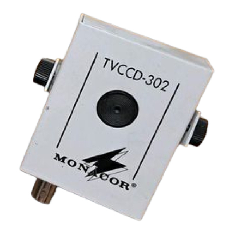
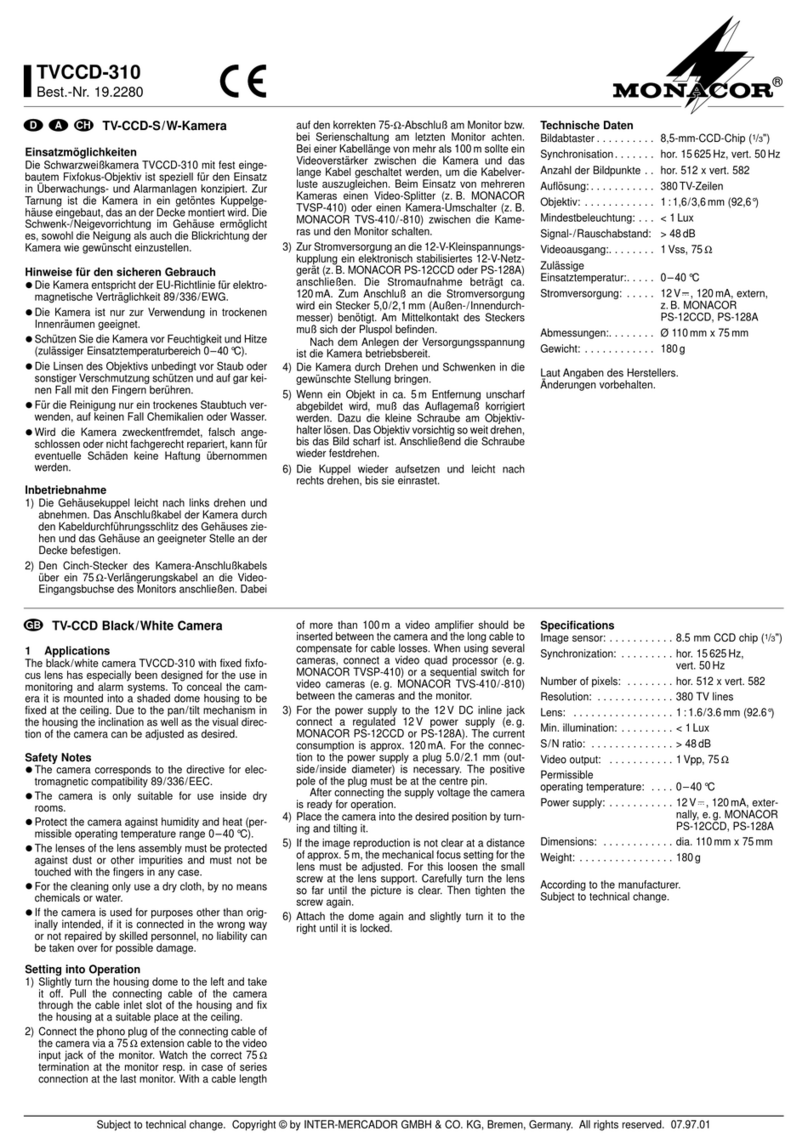
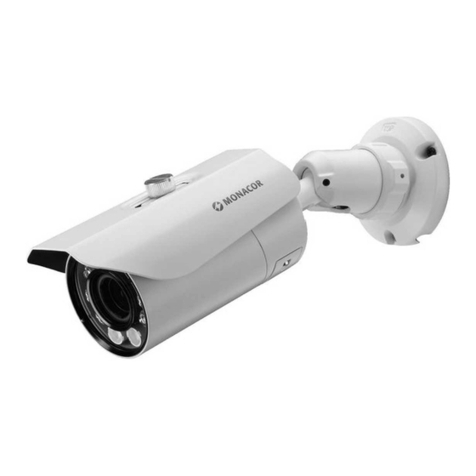
Monacor TVCCD-92A User manual

Schwarzweißkamera
1 Einsatzmöglichkeiten
Diese Schwarzweißkamera im Bewegungsmelder-
gehäuse ist speziell für den unauffälligen Einsatz in
Video-Überwachungsanlagen (CCTV) konzipiert und
wird an der Wand montiert.
Die Kamera ist mit einem 3,7-mm-Objektiv ausgestat-
tet und verfügt über eine automatische Helligkeitsre-
gelung. Über ein eingebautes Mikrofon liefert sie
zudem ein Audiosignal.
2 Hinweise für den sicheren Gebrauch
Die Kamera entspricht der EU-Richtlinie für elektro-
magnetische Verträglichkeit 89/336/EWG.
●Verwenden Sie die Kamera nur im Innenbereich.
Schützen Sie sie vor Tropf- und Spritzwasser, hoher
Luftfeuchtigkeit und Hitze (zulässiger Einsatztempe-
raturbereich 0–40°C).
●Schützen Sie die Objektivlinse vor Staub oder sons-
tiger Verschmutzung.
●Verwenden Sie für die Reinigung des Gerätes nur
ein weiches, trockenes Tuch, auf keinen Fall Was-
ser oder Chemikalien.
●Wird die Kamera zweckentfremdet, nicht richtig
montiert, falsch angeschlossen oder nicht fachge-
recht repariert, kann keine Haftung für daraus resul-
tierende Sach- oder Personenschäden und keine
Garantie für die Kamera übernommen werden.
SolldieKameraendgültigausdemBetrieb
genommen werden, übergeben Sie sie zur
umweltfreundlichen Entsorgung einem
örtlichen Recyclingbetrieb.
3 Inbetriebnahme
3.1 Montage
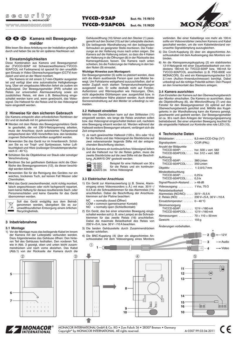
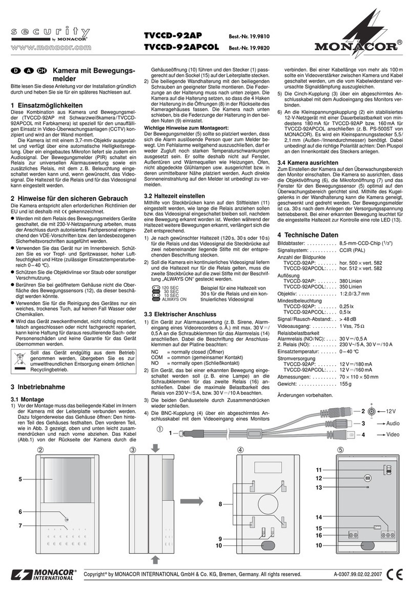
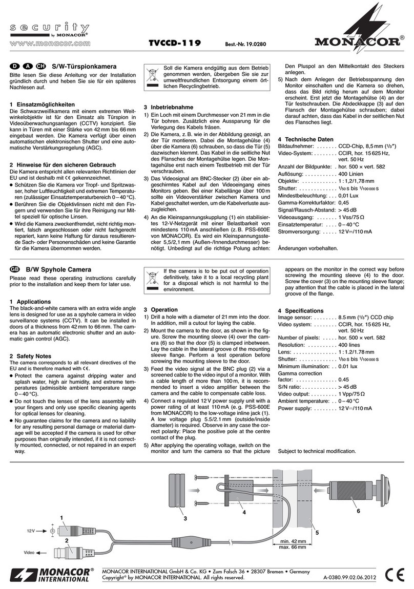
1) Vor der Montage muss das beiliegende Kabel im
Innern der Kamera mit der Leiterplatte verbunden
werden. Dazu folgenderweise das Gehäuse öff-
nen: Den hinteren Teil des Gehäuses festhalten.
Den vorderen Teil, wie in Abb. 3 gezeigt, oben und
unten leicht zusammendrücken und nach vorne
abziehen. Das Kabel (Abb.1) von der Rückseite der
Kamera durch die Gehäuseöffnung (9) führen und
den Stecker (1) passgerecht auf den Sockel (10)
auf der Leiterplatte stecken. Anschließend die bei-
den Gehäuseteile durch Zusammendrücken wie-
der schließen.
2) Die beiliegende Wandhalterung mit den beiliegen-
den Schrauben an geeigneter Stelle montieren. Die
Federzungeander Halterung muss nach unten zei-
gen. Die Kamera auf die Halterung setzen, so dass
die 4 Haken der Halterung in die Öffnungen (7) in
der Rückseite des Kameragehäuses fassen. Die
Kamera nach unten schieben, bis die Federzunge
der Halterung in den beiden Nuten (8) einrastet.
3.2 Elektrischer Anschluss
1) Die BNC-Kupplung (4) über ein abgeschirmtes An-
schlusskabelmitdem Videoeingang eines Monitors
verbinden. Bei einer Kabellänge von mehr als
100m sollte ein Videoverstärker zwischen Kamera
und Kabel geschaltet werden, um die vom Kabel-
widerstand verursachte Signaldämpfung auszu-
gleichen.
2) Die Cinch-Kupplung (3) über ein abgeschirmtes
Anschlusskabel mit dem Audioeingang des Moni-
tors verbinden.
3) An die Kleinspannungskupplung (2) ein stabilisier-
tes 12-V-Netzgerät mit einer Dauerbelastbarkeit
von mindestens 110mA anschließen (z.B. PS-
500ST von MONACOR). Es wird ein Kleinspan-
nungsstecker 5,5/2,1mm (Außen-/Innendurch-
messer) benötigt. Dabei unbedingt auf die richtige
Polarität achten: Den Pluspol an den Innenkontakt
des Steckers anlegen.
3.3 Kamera ausrichten
Zum Einstellen der Kamera auf den Überwachungs-
bereich den Monitor einschalten. Die Kamera so aus-
richten, dass die Objektivöffnung (5) und die Mikro-
fonöffnung (6) optimal auf den Überwachungsbereich
gerichtet sind. Mithilfe des Kugelgelenks in der Wand-
halterung kann die Kamera geneigt, geschwenkt und
gedreht werden.
4 Technische Daten
Bildabtaster: . . . . . . . . . . 8,5-mm-CCD-Chip (1/3")
Signalsystem:. . . . . . . . . CCIR
Synchronisation:. . . . . . . hor. 15625Hz, vert. 50Hz
Anzahl der Bildpunkte: . . hor. 500 x vert. 582
Auflösung: . . . . . . . . . . . 380 Linien
Objektiv: . . . . . . . . . . . . . 1:2,0/3,7mm
Mindestbeleuchtung: . . . 0,25lx
Signal/Rausch-Abstand: > 48dB
Videoausgang: . . . . . . . . 1Vss, 75Ω
Einsatztemperatur:. . . . . 0–40°C
Stromversorgung:. . . . . . 12V /110mA
Abmessungen: . . . . . . . . 70 x 110 x 50mm
Gewicht: . . . . . . . . . . . . . 125g
Laut Angaben des Herstellers.
Änderungen vorbehalten.
®
TVCCD-92A Best.-Nr. 19.9800
Copyright©by MONACOR INTERNATIONAL GmbH & Co. KG, Bremen, Germany. All rights reserved. A-0308.99.01.10.2004
®
5
6
7
8
910
Video
+
-
12V
Audio
1
2
3
4
➁➃➄
➀
➂
D A CH

Black-and-White Camera
1 Applications
This black-and-white camera in the motion detector
housing is especially designed for the inconspicuous
use in video surveillance systems (CCTV) and is
mounted to the wall.
The camera is equipped with a 3.7mm lens and
has an automatic brightness control. Via an installed
microphone it additionally supplies an audio signal.
2 Safety Notes
The camera corresponds to the directive 89/336/EEC
for electromagnetic compatibility.
●The camera is suitable for indoor use only. Protect it
against dripping water and splash water, high air
humidity, and heat (admissible ambient temperature
range 0–40°C).
●Protect the lens against dust and other impurities.
●For cleaning only use a dry, soft cloth, by no means
chemicals or water.
●No guarantee claims for the camera and no liability
for any resulting personal damage or material dam-
age will be accepted if the camera is used for other
purposes than originally intended, if it is not correct-
ly mounted, connected, or not repaired in an expert
way.
If the camera is to be put out of operation
definitively, take it to a local recycling plant
for a disposal which is not harmful to the
environment.
3 Setting into Operation
3.1 Mounting
1) Prior to mounting, the supplied cable has to be
connected to the PCB inside the camera. For this
purpose, open the housing as follows: Hold the rear
part of the housing. Slightly press together the front
part as shown in fig. 3 and remove it forwards.
Guide the cable (fig. 1) from the rear side of the
camera through the housing opening (9) and place
the plug (1) on the connector (10) of the PCB so
that it fits precisely. Then close the two housing
parts by pressing them together.
2) Mount the supplied wall bracket with the supplied
screws to a suitable place. The latch at the bracket
must show downwards. Place the camera on the
bracket so that the 4 hooks of the bracket catch in
theopenings (7) in the rearside of the camera hous-
ing. Slide the camera downwards until the latch of
the bracket engages into the two grooves (8).
3.2 Electrical connection
1) Connect the BNC inline jack (4) via a screened
audio cable to the video input of a monitor. With a
cable length of more than 100m a video amplifier
should be inserted between the camera and the
cable to compensate the signal attenuation caused
by the cable resistance.
2) Connect the phono inline jack (3) via a screened
cable to the audio input of the monitor.
3) Connect a regulated 12V power supply unit with a
permanentrating of at least 110mA(e.g.PS-500ST
from MONACOR) to the low-voltage inline jack (2).
A low-voltage plug 5.5/2.1mm (outside/inside di-
ameter)isrequired. Observe in any case the correct
polarity:Apply the positive pole to the inside contact
of the plug.
3.3 Adjusting the camera
Switch on the monitor for adjusting the camera to the
surveillance zone. Adjust the camera so that the lens
aperture (5) and the microphone aperture (6) are
directed to the surveillance zone in an optimum way.
By means of the ball joint in the wall bracket the cam-
era can be tilted, panned, and turned.
4 Specifications
Image sensor:. . . . . . . . . 8.5mm (1/3") CCD chip
Signal system: . . . . . . . . CCIR
Snychronization:. . . . . . . hor. 15625Hz, vert. 50Hz
Number of pixels: . . . . . . hor. 500 x vert. 582
Resolution: . . . . . . . . . . . 380 lines
Lens:. . . . . . . . . . . . . . . . 1:2.0/3.7mm
Minimum illumination:. . . 0.25lx
S/N ratio: . . . . . . . . . . . . > 48dB
Video output: . . . . . . . . . 1Vpp, 75Ω
Ambient temperature:. . . 0–40°C
Power supply:. . . . . . . . . 12V /110mA
Dimensions: . . . . . . . . . . 70 x 110 x 50mm
Weight:. . . . . . . . . . . . . . 125g
According to the manufacturer.
Subject to technical modification.
®
TVCCD-92A Order No. 19.9800
Copyright©by MONACOR INTERNATIONAL GmbH & Co. KG, Bremen, Germany. All rights reserved. A-0308.99.01.10.2004
®
5
6
7
8
910
Video
+
-
12V
Audio
1
2
3
4
➁➃➄
➀
➂
GB

Caméra noir et blanc
1 Possibilités d’utilisation
La caméra noir et blanc dans un boîtier de détecteur
de mouvements est spécialement conçue pour une
installation discrète dans des installations de vidéo-
surveillance (CCTV) et se monte sur un mur.
La caméra est dotée d’un objectif 3,7mm et dispo-
se d’un réglage automatique de luminosité. Via le
microphone intégré, elle délivre en plus un signal
audio.
2 Conseils d’utilisation et de sécurité
La caméra répond à la norme européenne 89/336/
CEE relative à la compatibilité électromagnétique.
●N’utilisez la caméra qu’en intérieur. Protégez-la de
tout type de projections d’eau, des éclaboussures,
d’une humidité élevée et de la chaleur (plage de
température de fonctionnement autorisée 0–40°C).
●Protégez la lentille de l’objectif de la poussière ou
toute autre salissure.
●Pour nettoyer la caméra, utilisez un chiffon sec et
doux, n’utilisez jamais de produits chimiques ou de
détergents.
●Nous déclinons toute responsabilité en cas de dom-
mages corporels ou matériels résultants si la
caméra est utilisée dans un but autre que celui pour
lequel elle a été conçue, si elle n’est pas correcte-
ment montée, branchée ou n’est pas réparée par
une personne habilitée, de même, la garantie
deviendrait caduque.
Lorsque la caméra est définitivement
retirée du service, vous devez la déposer
dans une usine de recyclage de proximité
pour contribuer à son élimination non pol-
luante.
3 Fonctionnement
3.1 Montage
1) Avant le montage, le cordon livré doit être relié au
circuit imprimé à l’intérieur de la caméra. Pour ce
faire, ouvrez le boîtier : maintenez la partie arrière
du boîtier. Comme indiqué sur le schéma 3, pres-
sez doucement la partie avant en haut et en bas
puis tirez vers l’avant. Faites passer le câble (sché-
ma 1) de la face arrière de la caméra via l’ouvertu-
re du boîtier (9) et connectez la fiche (1) de maniè-
re à ce qu’il s’encastre correctement sur la borne
(10) située sur le circuit imprimé. Ensuite, refermez
les deux parties du boîtier en les pressant l’une
contre l’autre.
2) Montez le support mural livré avec les vis fournies
à l’endroit voulu. La languette sur le support doit
être dirigée vers le bas. Placez la caméra sur le
support de telle sorte que les quatre crochets du
support entrent dans les ouvertures (7) de la face
arrière du boîtier de la caméra. Faites glisser la
caméra vers le bas jusqu’à ce que la languette du
support s’encastre dans les deux encoches (8).
3.2 Branchement électrique
1) Reliez la fiche femelle BNC (4) via un cordon blin-
dé à l’entrée vidéo d’un moniteur. Pour une lon-
gueur de câble supérieure à 100m, il est recom-
mandé d’installer un amplificateur vidéo entre la
caméra et le câble pour compenser l’atténuation du
signal causée par la résistance du câble.
2) Reliez la fiche RCA (3) via un cordon blindé à l’en-
trée audio du moniteur.
3) Connectez une alimentation stabilisée 12V avec
une charge permanente de 110mA au moins (par
exemple PS-500ST de MONACOR) à la fiche d’ali-
mentation (2). Un adaptateur 5,5/2,1mm (diamètre
extérieur/intérieur) est nécessaire. Veillez impéra-
tivement à respecter la polarité : mettez le pôle plus
au contact intérieur de la fiche.
3.3 Orientation de la caméra
Pour régler la caméra sur la zone de surveillance, allu-
mez le moniteur. Dirigez la caméra de sorte que l’ou-
verture de l’objectif (5) et l’ouverture du micro (6)
soient orientées de manière optimale vers la zone de
surveillance. A l’aide de l’articulation à rotule dans le
support mural, il est possible d’incliner la caméra vers
le haut et le bas et de l’orienter de droite à gauche.
4 Caractéristiques techniques
Puce :. . . . . . . . . . . . . . . CCD 8,5mm (1/3")
Système signal :. . . . . . . CCIR
Synchronisation : . . . . . . hor. 15625Hz, vert. 50Hz
Nombre de points :. . . . . hor. 500 x vert. 582
Résolution : . . . . . . . . . . 380 lignes
Objectif :. . . . . . . . . . . . . 1:2,0/3,7mm
Luminosité minimale :. . . 0,25lux
Rapport signal/bruit : . . . > 48dB
Sortie vidéo : . . . . . . . . . 1Vcc, 75Ω
Température
fonctionement :. . . . . . . . 0–40°C
Alimentation : . . . . . . . . . 12V /110mA
Dimensions :. . . . . . . . . . 70 x 110 x 50mm
Poids : . . . . . . . . . . . . . . 125g
D’après les données du constructeur.
Tout droit de modification réservé.
®
TVCCD-92A Ref. num. 19.9800
Copyright©by MONACOR INTERNATIONAL GmbH & Co. KG, Bremen, Germany. All rights reserved. A-0308.99.01.10.2004
®
5
6
7
8
910
Video
+
-
12V
Audio
1
2
3
4
➁➃➄
➀
➂
F B CH

Telecamera b/n
1 Possibilità di impiego
Questa telecamera nel contenitore di un segnalatore
di movimento è stata realizzata specialmente per l’im-
piego non vistoso in impianti di sorveglianza video
(CCTV) ed è prevista per il montaggio a parete.
La telecamera è equipaggiata con un obiettivo di
3,7mm e dispone di regolazione automatica della
luminosità. Grazie al microfono integrato è in grado di
fornire anche un segnale audio.
2 Avvertenze di sicurezza
La telecamera è conforme alla direttiva CE 89/336/
CEE sulla compatibilità elettromagnetica.
●Far funzionare la telecamera solo all’interno di loca-
li. Proteggerla dall’acqua gocciolante e dagli spruz-
zid’acqua, da alta umidità dell’aria e dal calore (tem-
peratura d’impiego ammessa fra 0 e 40°C).
●Proteggere la lente dell’obiettivo dalla polvere e
dallo sporco in genere.
●Per la pulizia usare solo un panno morbido, asciut-
to; non impiegare in nessun caso prodotti chimici o
acqua.
●Nel caso d’uso improprio, di montaggio errato, di
collegamenti sbagliati o di riparazione non a regola
d’arte della telecamera, non si assume nessuna re-
sponsabilità per eventuali danni consequenziali a
persone o a cose e non si assume nessuna garan-
zia per la telecamera.
Se si desidera eliminare la telecamera de-
finitivamente, consegnarla per lo smalti-
mento ad un’istituzione locale per il rici-
claggio.
3 Messa in funzione
3.1 Montaggio
1) Prima del montaggio occorre collegare il cavo in
dotazione con il circuito stampato all’interno della
telecamera. Per fare ciò aprire il contenitore: tene-
re ferma la parte posteriore del contenitore. Eserci-
tare una leggera pressione sulla parte anteriore,
come da fig. 3, e precisamente sotto e sopra e sfi-
lare la parte anteriore verso il davanti. Fare passa-
re il cavo (fig.1) dal retro della telecamera attraver-
so il passacavo del contenitore (9) e inserire il con-
nettore (1) nello zoccolo (10) del circuito stampato.
Quindi chiudere le due parti del contenitore spin-
gendole l’una contro l’altra
2) Montare il supporto da parete in un posto adatto,
servendosi delle viti in dotazione. La linguetta del
supporto deve essere rivolta verso il basso. Inseri-
re la telecamera nel supporto in modo tale che i 4
ganci del supporto entrino nelle aperture (7) sul
retro della telecamera. Spingere la telecamera
verso il basso finché la linguetta del supporto entra
a scatto nelle due scanalature (8).
3.2 Collegamento elettrico
1) Collegare la presa BNC (4) con l’ingresso video di
un monitor servendosi di un cavo schermato di col-
legamento. Nel caso di un cavo di oltre 100m di
lunghezza, conviene inserire un amplificatore video
fra telecamera e cavo per compensare l’attenua-
zione del segnale causata dalla resistenza del
cavo.
2) Collegare la presa RCA(3) con l’ingresso audio del
monitor per mezzo di un cavo schermato di colle-
gamento.
3) Alla presa per alimentazione DC (2) si deve colle-
gare un alimentatore stabilizzato per 12V con po-
tenza permanente di 110mAmin. (p.es. PS-500ST
di MONACOR). È richiesto uno spinotto di 5,5/
2,1mm (diametro esterno/interno). Fare assoluta-
mente attenzione alla corretta polarità: il polo posi-
tivo deve essere collegato con il contatto interno
del connettore.
3.3 Orientare la telecamera
Per regolare la telecamera rispetto alla zona da sor-
vegliare accendere il monitor. Orientare la telecamera
in modo tale che l’apertura per l’obiettivo (5) e quella
per il microfono (6) siano orientati in modo ottimale
sulla zona da sorvegliare. Con l’aiuto del giunto sferi-
co nel supporto a parete, la telecamera può essere
inclinata, basculata e girata.
4 Dati tecnici
Sensore ottico: . . . . . . . . chip CCD 8,5mm (1/3")
Sistema di
segnale video: . . . . . . . . CCIR
Sincronizzazione:. . . . . . orizz. 15625Hz,
vert. 50Hz
Numero pixel:. . . . . . . . . orizz. 500 x vert. 582
Risoluzione: . . . . . . . . . . 380 linee
Obiettivo: . . . . . . . . . . . . 1:2,0/3,7mm
Illuminazione minima:. . . 0,25 lx
Rapporto S/R: . . . . . . . . > 48dB
Uscita video:. . . . . . . . . . 1Vpp, 75Ω
Temperatura d’esercizio: 0–40°C
Alimentazione: . . . . . . . . 12V /110mA
Dimensioni:. . . . . . . . . . . 70 x 110 x 50mm
Peso: . . . . . . . . . . . . . . . 125g
Dati forniti dal costruttore.
Con riserva di modifiche tecniche.
®
TVCCD-92A N. articolo 19.9800
Copyright©by MONACOR INTERNATIONAL GmbH & Co. KG, Bremen, Germany. All rights reserved. A-0308.99.01.10.2004
®
5
6
7
8
910
Video
+
-
12V
Audio
1
2
3
4
➁➃➄
➀
➂
I

Cámara blanco- negro
1 Aplicaciones
Esta cámara blanco-negro en la carcasa de detector
de movimientos está especialmente diseñada para la
utilización discreta en sistemas de vigilancia vídeo
(CCTV) y se monta en la pared.
La cámara está equipada con una lente de 3,7mm
y tiene un control automático de brillo. Vía un micrófo-
no instalado proporciona adicionalmente una señal
audio.
2 Consejos de utilización
La cámara cumple la normativa europea 89/336/CEE
relativa a la compatibilidad electromagnética.
●La cámara está concebida sólo para una utilización
en interior Protegerla de todo tipo de proyecciones
de aguas, de salpicaduras, de la humedad elevada
y del calor (rango de temperaturas de funcio-
namiento autorizado 0–40°C).
●Proteger la lente del polvo y otras impurezas.
●Para limpiar el aparato, utilizar solo un paño seco y
blando, en ningún caso, productos químicos o agua.
●Declinamos cualquier responsabilidad en caso de
daños materiales o corporales resultandos si la
cámara se utiliza para otro fin que no sea el que ha
sido concebida, si no se monta o conecta correcta-
mente o si no es reparada por una persona cualifi-
cada; por estos mismos motivos carecería todo tipo
de garantía.
Cuando se retira definitivamente la cáma-
ra del servicio, debe depositarse en una
fábrica de reciclaje adaptada para su eli-
minación no contaminante.
3 Funcionamiento
3.1 Montaje
1) Antes de montarla, el cable proporcionado debe
conectarse al PCB de dentro de la cámara. Para
este propósito, abrir la carcasa de la siguiente
manera: sujetar la parte trasera de la carcasa. Sua-
vemente presionar la parte frontal de arriba y de
abajo como se muestra en la fig. 3 y sacarla hacia
delante. Dirigir el cable (fig. 1) de la parte trasera
de la cámara a través de la apertura de la carcasa
(9) y colocar la toma (1) en el conector (10) de la
PCB de manera que encaje de forma precisa.
Luego cerrar las dos partes de la carcasa apretán-
dolas a la vez.
2) Montar la abrazadera de pared proporcionada con
los tornillos proporcionados en el lugar adecuado.
El cierre de la abrazadera debe estar hacia abajo.
Colocar la cámara encima de la abrazadera de
manera que los 4 ganchos de la abrazadera enca-
jenenlas aperturas (7) en la parte trasera de la car-
casa de la cámara. Deslizar la cámara hacia abajo
hasta que el cierre de la abrazadera encaje en los
dos surcos (8).
3.2 Conexión eléctrica
1) Conectar la toma de línea BNC (4) vía un cable
blindado a la entrada vídeo del monitor. Con una
longitud de cable superior a 100m un amplificador
vídeo debería instalarse entre la cámara y el cable
para compensar la atenuación de la señal causada
por la resistencia del cable.
2) Conectar la toma phono de línea (3) vía un cable
blindado a la entrada audio del monitor.
3) Conectar una unidad de alimentación regulada de
12V con una capacidad permanente de al menos
110mA (por ejemplo PS-500ST de MONACOR) a
la toma de bajo voltaje (2). Se necesita una toma
de bajo voltaje 5,5/2,1mm (diámetro exterior/inte-
rior). Observar en cualquier caso la polaridad co-
rrecta: colocar el polo positivo al contacto interior
de la toma.
3.3 Ajustes de cámara
Conectar el monitor para ajustar la cámara a la zona
de vigilancia. Ajustar la cámara de manera que la
apertura de la lente (5) y la apertura del micrófono (6)
se dirigan a la zona de vigilancia de manera óptima.
Mediante la junta de bola de la abrazadera de pared,
la cámara puede girarse, desplazarse horizontalmen-
te y verticalmente.
4 Especificaciones
Sensor imagen: . . . . . . . 8,5mm (1/3") CCD chip
Sistema señal: . . . . . . . . CCIR
Sincronización:. . . . . . . . hor. 15625Hz, vert. 50Hz
Número píxels:. . . . . . . . hor. 500 x vert. 582
Resolución:. . . . . . . . . . . 380líneas
Lente: . . . . . . . . . . . . . . . 1:2,0/3,7mm
Iluminación mín.: . . . . . . 0,25lx
Relación señal/ruido:. . . > 48dB
Salida vídeo:. . . . . . . . . . 1Vpp, 75Ω
Temperatura ambiente: . 0–40°C
Alimentación: . . . . . . . . . 12V /110mA
Dimensiones: . . . . . . . . . 70 x 110 x 50mm
Peso: . . . . . . . . . . . . . . . 125g
Datos según fabricante.
Sujeto a modificaciones técnicas.
®
TVCCD-92A Ref. num. 19.9800
Copyright©by MONACOR INTERNATIONAL GmbH & Co. KG, Bremen, Germany. All rights reserved. A-0308.99.01.10.2004
®
5
6
7
8
910
Video
+
-
12V
Audio
1
2
3
4
➁➃➄
➀
➂
E

Kamera czarno-biała
1Zastosowanie
TVCCD-92A jest czarno-białą kamerą w obudowie
imitującej czujnik ruchu, a przez to nie wzbudzająca
podejrze . Jest przeznaczona dla systemów monito-
ringu, montowana jest do ściany.
Kamera jest wyposażona w obiektyw 3,7 mm,
posiada automatyczną regulację jasności oraz wbu-
dowany mikrofon do transmisji sygnału audio.
2Środki bezpieczeństwa
Urządzenie odpowiada normie o zgodności elektro-
magnetycznej 89/336/EEC.
●Kamera jest przeznaczona tylko do użytku
wewnątrz pomieszcze . Urządzenie należy chronić
przed wilgocią i wysoką temperaturą (dopuszczal-
ny zakres temperatury to 0 – 40 °C).
●Chronić obiektyw przed kurzem oraz innymi
zanieczyszczeniami.
●Do czyszczenia obudowy używać suchej, miękkiej
ściereczki. Nie stosować wody ani środków czy-
szczących.
●Producent ani dostawca nie ponosi odpowiedzial-
ności za wynikłe szkody materialne, jeśli urządze-
nie było używane niezgodnie z przeznaczeniem,
zostało zainstalowane lub obsługiwane niepopra-
wnie lub poddawane nieautoryzowanym napra-
wom.
Jeśli urządzenie nie będzie już nigdy
więcej używane, wskazane jest przekaza-
nie go do miejsca utylizacji odpadów, aby
zostało utylizowane bez szkody dla
środowiska.
3Przygotowanie do pracy
3.1 Montaż
1) Przed zamontowaniem kamery należy podpiąć do
płytki PCB załączony przewód. W tym celu należy
otworzyć obudowę: Przytrzymać tylną część obu-
dowy. Lekko ścisnąć przednią część obudowy jak
pokazano na rysunku 3 a następnie zdjąć ją.
Wprowadzić przewód pokazany na rys. 1 od tyłu
obudowy przez otwór (9) i wetknąć wtyk (1) do
gniazda (10). Następnie zamknąć obudowę.
2) Zamocować dołączony uchwyt ścienny w wyma-
ganym miejscu. Zatrzask na uchwycie powinien
być skierowany w dół. Umieścić kamerę na uch-
wycie aby 4 zatrzaski weszły w otwory montażowe
(7) znajdujące się z tyłu obudowy. Pociągnąć w
dół kamerę dopóki zatrzaski uchwytu nie znajdą
się w dwóch rowkach (8).
3.2 Podłączenie elektryczne
1) Połączyć gniazdo nakablowe typu BNC (4) wyko-
rzystując ekranowany kabel z wejściem wideo
monitora. Jeśli długość połączenia będzie prze-
kraczać 100 m należy zastosować wzmacniacz
wideo i wpiąć go pomiędzy monitorem a kamerą,
ze względu na straty sygnału spowodowane rezy-
stancją przewodu.
2) Połączyć gniazdo nakablowe typu chinch (3) za
pomocą ekranowanego przewodu z wejściem
audio monitora.
3) Podłączyć zasilacz stabilizowany 12 V o minimal-
nej wydajności prądowej 110 mA (np. MONACOR
PS-500ST) do gniazda nakablowego (2). Wyma-
gany jest wtyk o wymiarach 5,5/2,1 mm
(zewnętrzna/wewnętrzna średnica). Należy zwró-
cić uwagę na odpowiednia polaryzację pinów:
wewnętrzny pin jest stykiem dodatnim.
3.3 Ustawianie kamery
Aby ustawić kamerę i jej parametry w stosunku do
kontrolowanego obszaru należy wcześniej włączyć
monitor. Ustawić kamerę tak, aby otwór obiektywu
(5) oraz mikrofonu (6) był skierowany optymalnie na
monitorowany obszar. Uchwyt montażowy jest wypo-
sażony w złącze kulowe, dlatego też możliwa jest
regulacja położenia kamery we wszystkich kierun-
kach.
4ane techniczne
Przetwornik obrazu:. . . . 8,5 mm (1/3") chip CCD
System: . . . . . . . . . . . . . CCIR
Synchronizacja: . . . . . . . pozioma 15 625 Hz, pio-
nowa 50 Hz
Piksele:. . . . . . . . . . . . . . 500 x 582 (poziom x pion)
Rozdzielczość: . . . . . . . . 380 linii
Obiektyw: . . . . . . . . . . . . 1:2,0/3,7 mm
Minimalna jasność . . . . . 0,25 lux
Stosunek S/N:. . . . . . . . > 48 dB
Wyjście video:. . . . . . . . . 1 Vpp/75 Ω
Temperatura pracy: . . . . 0 – 40°C
Zasilanie: . . . . . . . . . . . . 12 V /110 mA
Wymiary:. . . . . . . . . . . . . 70 x 110 x 50 mm
Waga: . . . . . . . . . . . . . . . 125 g
Zgodnie z danymi producenta
Z zastrzeżeniem do możliwych zmian.
®
TVCCD-92A Numer zam. 19.9800
Copyright©by MONACOR INTERNATIONAL GmbH & Co. KG, Bremen, Germany. All rights reserved. A-0308.99.01.10.2004
®
5
6
7
8
910
Video
+
-
12V
Audio
1
2
3
4
➁➃➄
➀
➂
PL
This manual suits for next models
1
Table of contents
Languages:
Other Monacor Digital Camera manuals

Monacor
Monacor INC-4312BBVM User manual

Monacor
Monacor TVCCD-302 User manual

Monacor
Monacor TVCCD-124 User manual

Monacor
Monacor TVC-500 User manual

Monacor
Monacor TVCCD-310 User manual

Monacor
Monacor TVCCD-95 User manual

Monacor
Monacor TVCCD-119 User manual

Monacor
Monacor AV-420SET User manual

Monacor
Monacor security TVCCD-92AP User manual

Monacor
Monacor TVCCD-92AP User manual