manuals.online logo
Brands
  1. Home
  2. •
  3. Brands
  4. •
  5. Monacor
  6. •
  7. Speakers System
  8. •
  9. Monacor ESP-80/WS User manual

Monacor ESP-80/WS User manual

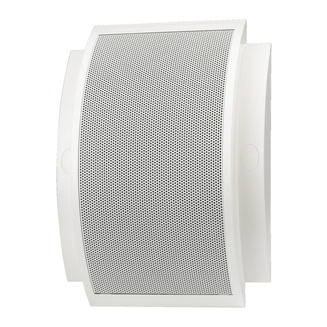
ELA-Wandlautsprecher
Bitte lesen Sie diese Anleitung vor der Installation
gründlich durch und heben Sie sie für ein späteres
Nachlesen auf.
1 Verwendungsmöglichkeiten
Dieser Wandlautsprecher ist speziell für den Einsatz in
ELA-Anlagen, die mit 100-V-Technik arbeiten, konzi-
piert. Er eignet sich optimal zur Wiedergabe von Spra-
che und Hintergrundmusik. Das stabile Metallgehäuse
bietet Schutz vor Beschädigungen (z. B. durch Ball-
würfe).
2 Wichtige Hinweise für den Gebrauch
Der Lautsprecher entspricht allen erforderlichen Richt-
linien der EU und ist deshalb mit gekennzeichnet.
GDer Lautsprecher ist nur zur Verwendung im Innen-
bereich geeignet. Schützen Sie ihn vor Tropf- und
Spritzwasser, hoher Luftfeuchtigkeit und Hitze (zu-
lässiger Einsatztemperaturbereich 0 – 40 °C).
GVerwenden Sie für die Reinigung nur ein trockenes,
weiches Tuch, niemals Wasser oder Chemikalien.
GWird der Lautsprecher zweckentfremdet, nicht fach-
gerecht installiert oder überlastet, kann keine Haf-
tung für daraus resultierende Sach- oder Personen-
schäden und keine Garantie für den Lautsprecher
übernommen werden.
Soll der Lautsprecher endgültig aus dem
Betrieb genommen werden, übergeben Sie
ihn zur umweltgerechten Entsorgung einem
örtlichen Recyclingbetrieb.
3 Montage
1) Die drei Schrauben am Gehäuse abschrauben.
2) Die Gehäusefront vorsichtig von der Gehäuserück-
seite abnehmen. Die Gehäuseteile sind über die
Lautsprecherleitungen miteinander verbunden. Da-
mit die Front ganz abgenommen werden kann, die
Lautsprecherleitungen am Lautsprecher abziehen.
3) Die Anschlussleitungen von hinten durch den
Kabeldurchlass in der Mitte der Gehäuserückseite
führen. Sollen sie statt von hinten von oben in das
Gehäuse geführt werden, an der Oberkante der
Gehäuserückseite an einer der Sollbruchstellen
einen Kabeldurchlass herausbrechen.
4) Die Gehäuserückseite mit geeignetem Montage-
material an der Wand befestigen.
5) Den elektrischenAnschluss herstellen (→Kapitel 4).
6) Die Lautsprecherleitungen (schwarz = minus, rot =
plus) wieder mit dem Lautsprecher verbinden, die
Gehäusefront aufsetzen und festschrauben.
4 Anschluss
WARNUNG Im Betrieb liegt berührungsgefährliche
Spannung bis 100 V an der Anschluss-
leitung an.
Die Installation darf nur durch Fachper-
sonal erfolgen!
Achten Sie auf die Belastung des ELA-Verstärkers
durch die Lautsprecher. Eine Überlastung kann den
Verstärker beschädigen! Die Summe der Leistungen
aller angeschlossenen Lautsprecher darf die Verstär-
kerleistung nicht überschreiten.
1) Die ELA-Anlage vor dem Anschluss komplett aus-
schalten, damit die 100-V-Audioleitung vom ELA-
Verstärker spannungsfrei ist!
2) Den Lautsprecher über die Klemmen „IN
-
“ und
„IN+“ mit der 100-V-Audioleitung vom ELA-Verstär-
ker verbinden.
3) Um die Nennleistung (Lautstärke) für den Lautspre-
cher einzustellen, am Übertrager die rote Leitung
auf denjenigen Kontakt stecken, dessen Beschrif-
tung der gewünschten Nennleistung (6 W, 3 W,
1,5 W oder 0,75 W) entspricht.
4) Über die Klemmen „OUT
-
“ und „OUT+“ kann ein
weiterer ELA-Lautsprecher mit der 100-V-Audio-
leitung verbunden werden.
5) Über die Klemme kann das Gehäuse geerdet
werden.
Beim Anschluss von mehreren Lautsprechern darauf
achten, dass sie alle gleich gepolt werden und dass
der ELA-Verstärker nicht überlastet wird.
5 Technische Daten
Frequenzbereich: . . . . . 250 – 10 000 Hz
Nennbelastbarkeit/
Impedanz: . . . . . . . . . . . 6 WRMS/1,67 kΩ
3 WRMS/3,33 kΩ
1,5 WRMS/6,67 kΩ
0,75 WRMS/13,33 kΩ
Abmessungen: . . . . . . . 170 × 170 × 63 mm
Gewicht: . . . . . . . . . . . . 1,3 kg
Änderungen vorbehalten.
ESP-80/ WS Best.-Nr. 16.2380
PA Wall Speaker
Please read these operating instructions carefully
prior to installation and keep them for later reference.
1 Applications
This wall speaker is specially designed for applica-
tions in PA systems operating with a 100 V technique.
It is ideally suited for reproducing speech and back-
ground music. The stable metal housing offers protec-
tion against damage, e. g. ball impacts.
2 Important Notes
The speaker corresponds to all required directives of
the EU and is therefore marked with .
GThe speaker is suitable for indoor use only. Protect
it against dripping water and splash water, high air
humidity, and heat (admissible ambient temperature
range 0 – 40 °C).
GFor cleaning only use a dry, soft cloth; never use
water or chemicals.
GNo guarantee claims for the speaker and no liability
for any resulting personal damage or material dam-
age will be accepted if the speaker is used for other
purposes than originally intended, if it is not correctly
installed, or if it is overloaded.
If the speaker is to be put out of operation
definitively, take it to a local recycling plant for
a disposal which is not harmful to the envi-
ronment.
3 Mounting
1) Unscrew the three screws on the housing.
2) Carefully remove the front panel of the housing from
the rear panel of the housing. The housing parts are
connected to each other via the speaker cables.
Disconnect the speaker cables from the speaker so
that the front panel can be fully removed.
3) Guide the connection cables from the rear through
the cable entry hole in the centre of the rear panel.
For guiding the cables into the housing from the top
instead of from the rear, open one of the knockout
holes at the upper edge of the rear panel.
4) Fasten the rear panel of the housing to the wall via
suitable mounting material.
5) Make the electrical connection (→chapter 4).
6) Reconnect the speaker cables (black = negative,
red = positive) to the speaker, replace the front
panel and screw it on.
4 Connection
WARNING During operation, there is a hazard of
contact with a voltage up to 100 V at the
connection cable.
Installation must be carried out by
skilled personnel only!
Observe the load of the PA amplifier by the speakers.
An overload may damage the amplifier! The total
power of all speakers connected must not exceed the
amplifier power.
1) Prior to connection, switch off the PA system com-
pletely so that the 100 V audio cable from the PA
amplifier will not carry any voltage!
2) Connect the speaker via the terminals “IN
-
” and
“IN+” to the 100 V audio cable from the PA amplifier.
3) To adjust the power rating (volume) for the speaker,
connect the red cable on the transformer to the con-
tact corresponding to the desired power rating (6 W,
3 W, 1.5 W or 0.75 W).
4) The terminals “OUT
-
” and “OUT+” allow connection
of another PA speaker to the 100 V audio cable.
5) Via the terminal , the housing can be earthed.
When connecting several speakers, make sure that all
speakers have the same polarity and that the PA
amplifier is not overloaded.
5 Specifications
Frequency range: . . . . . 250 – 10 000 Hz
Power rating/impedance: 6 WRMS/1.67 kΩ
3WRMS/3.33 kΩ
1.5 WRMS/6.67 kΩ
0.75 WRMS/13.33 kΩ
Dimensions: . . . . . . . . . 170 × 170 × 63 mm
Weight: . . . . . . . . . . . . . 1.3 kg
Subject to technical modification.
®
MONACOR INTERNATIONAL GmbH & Co. KG • Zum Falsch 36 • 28307 Bremen • Germany
Copyright©by MONACOR INTERNATIONAL. All rights reserved. A-0850.99.02.08.2011
®
D A CH
GB
Haut-parleur
Public Adress mural
Veuillez lire la présente notice avec attention avant
lʼinstallation et conservez-la pour pouvoir vous y
reporter ultérieurement.
1 Possibilités dʼutilisation
Ce haut-parleur mural est spécialement conçu pour
une utilisation dans des installations de Public Adress
fonctionnant en ligne 100 V. Il est idéal pour une resti-
tution optimale de la parole et de la musique de fond.
Le boîtier métallique solide le protège des dommages
(par exemple jets de ballon).
2 Conseils importants dʼutilisation
Le haut-parleur répond à toutes les directives néces-
saires de lʼUnion européenne et porte donc le symbole
.
GLʼappareil nʼest conçu que pour une utilisation en
intérieur. Protégez-le des éclaboussures, de tout
type de projections dʼeau, dʼune humidité élevée de
lʼair et de la chaleur (température ambiante admissi-
ble 0 – 40 °C).
GPour le nettoyage, utilisez uniquement un chiffon
sec et doux, en aucun cas de produits chimiques ou
dʼeau.
GNous déclinons toute responsabilité en cas de dom-
mages matériels ou corporels résultants si le haut-
parleur est utilisé dans un but autre que celui pour
lequel il a été conçu, sʼil nʼest pas correctement ins-
tallé ou sʼil y a surcharge ; en outre, la garantie
deviendrait caduque.
3 Montage
1) Dévissez les trois vis sur le boîtier.
2) Retirez avec précaution la façade du boîtier de la
face arrière du boîtier. Les deux éléments du boîtier
sont reliés entre eux par les câbles haut-parleurs.
Pour pouvoir retirer la façade, déconnectez les
câbles haut-parleur du haut-parleur.
3) Faites passer les câbles de branchement par lʼar-
rière, au milieu de la face arrière du boîtier, via le
trou dʼentrée du câble. Si les câbles doivent passer
par le haut et non par lʼarrière, ouvrez, sur lʼarête
supérieure de la face arrière du boîtier, un des trous
de découpe pour passage pour les câbles.
4) Fixez la face arrière du boîtier au mur avec le maté-
riel de montage adéquat.
5) Effectuez le branchement électrique (→voir chapi-
tre 4).
6) Reliez les câbles haut-parleur (noir = moins, rouge
= plus) au haut-parleur, replacez la façade et revis-
sez lʼensemble.
4 Branchement
AVERTISSEMENT Pendant le fonctionnement, une
tension de contact dangereuse
jusquʼà 100 V est présente au
câble de branchement.
Seul un personnel qualifié peut
effectuer lʼinstallation.
Lorsque le haut-parleur est définitivement
retiré du service, vous devez le déposer dans
une usine de recyclage adaptée pour contri-
buer à son élimination non polluante.
1) Eteignez lʼintégralité de lʼinstallation Public Adress
avant dʼeffectuer le branchement électrique du haut-
parleur pour que le câble audio 100 V de lʼamplifica-
teur Public Adress ne soit pas porteur de tension !
2) Reliez le haut-parleur au câble audio 100 V de lʼam-
plificateur Public Adress via les bornes “IN
-
” et “IN+”.
3) Pour régler la puissance nominale (volume) pour le
haut-parleur, reliez, sur le transformateur, le câble
rouge au contact dont le repère correspond à la
puissance nominale souhaitée (6 W, 3 W, 1,5 W ou
0,75 W).
4) Via les bornes “OUT
-
“ et OUT+“, on peut relier un
autre haut-parleur Public Adress au câble audio
100 V.
5) Le boîtier peut être relié à la terre via la borne .
Si plusieurs haut-parleurs sont reliés, veillez à ce quʼils
aient tous la même polarité et que lʼamplificateur
Public Adress ne soit pas en surcharge.
5 Caractéristiques techniques
Bande passante : . . . . . 250 – 10000 Hz
Puissance
nominale/Impédance : . 6 WRMS/1,67 kΩ
3W
RMS/3,33 kΩ
1,5 WRMS/6,67 kΩ
0,75 WRMS/13,33 kΩ
Dimensions, poids : . . . .170 × 170 × 63 mm, 1,3 kg
Tout droit de modification réservé.
Faites attention à la charge de lʼamplificateur PA par
les haut-parleurs. Une surcharge peut endommager
lʼamplificateur. La somme des puissances de lʼen-
semble des haut-parleurs reliés ne doit pas dépasser
la puissance de lʼamplificateur.
ESP-80/ WS Best.-Nr. 16.2380
Diffusore PA da parete
Vi preghiamo di leggere attentamente le presenti istru-
zioni prima dellʼinstallazione e di conservarle per un
uso futuro.
1 Possibilità dʼimpiego
Questo diffusore da parete è stato realizzato special-
mente per lʼimpiego in impianti PA che funzionano con
uscita audio 100 V. È adatto in maniera ottimale alla
riproduzione di lingua parlata e di musica di sotto-
fondo. Il robusto contenitore metallico lo protegge dai
danneggiamenti (p. es. da lanci di palloni).
2 Avvertenze importanti per lʼuso
Questʼapparecchio è conforme a tutte le direttive
richieste dellʼUE e pertanto porta la sigla .
GIl diffusore è previsto solo per lʼuso allʼinterno di
locali. Proteggerlo dallʼacqua gocciolante e dagli
spruzzi dʼacqua, da alta umidità dellʼaria e dal calore
(temperatura dʼimpiego ammessa fra 0 e 40 °C).
GPer la pulizia usare solo un panno morbido, asciutto;
non impiegare in nessun caso prodotti chimici o
acqua.
GNel caso dʼuso improprio, dʼinstallazione sbagliata
o di sovraccarico dellʼaltoparlante, non si assume
nessuna responsabilità per eventuali danni conse-
quenziali a persone o a cose e non si assume nes-
suna garanzia per il diffusore.
Se si desidera eliminare il diffusore definiti-
vamente, consegnarlo per lo smaltimento ad
unʼistituzione locale per il riciclaggio.
3 Montaggio
1) Svitare le tre viti sul contenitore.
2) Staccare il frontale delicatamente dal retro del con-
tenitore. Le parti del contenitore sono collegati fra di
loro per mezzo dei cavi per lʼaltoparlante. Per poter
togliere il frontale completamente, sfilare i cavi del-
lʼaltoparlante dallo stesso.
3) Fare passere i cavi di collegamento dal di dietro
attraverso il passacavi nel centro del lato posteriore
del contenitore. Se invece di passare dal di dietro, i
cavi devono passare dallʼalto, occorre creare un
passacavi in uno dei punti previsti per lʼapertura.
4) Fissare il retro del contenitore alla parete per mezzo
di materiali adatti per il montaggio.
5) Effettuare il collegamento elettrico (→Capitolo 4).
6) Collegare nuovamente i cavi dellʼaltoparlante con
lʼaltoparlante (nero = negativo, rosso = positivo),
rimettere il frontale ed avvitarlo.
4 Connessione
AVVERTIMENTO Durante il funzionamento, nel
cavo di collegamento è presente
una tensione fino a 100 V, perico-
losa in caso di contatto.
Lʼinstallazione deve essere ese-
guita solo da personale specializ-
zato.
Tener presente anche la potenza dellʼamplificatore
PA rispetto agli altoparlanti. Un sovraccarico può
danneggiare lʼamplificatore! La somma delle potenze
di tutti gli altoparlanti collegati non deve superare la
potenza dellʼamplificatore.
1) Prima di effettuare la connessione, spegnere com-
pletamente lʼimpianto PA, affinché la linea audio
100 V dallʼamplificatore PA sia esente di tensione!
2) Collegare lʼaltoparlante con la linea audio 100 V dal-
lʼamplificatore PA per mezzo dei morsetti “IN
-
” e
“IN+”.
3) Per impostare la potenza nominale (volume) per
lʼaltoparlante, inserire sul trasformatore il cavetto
rosso sul contatto la cui scritta corrisponde alla
potenza nominale desiderata (6 W, 3 W, 1,5 W o
0,75 W).
4) Per mezzo dei morsetti “OUT
-
” e “OUT+” è possi-
bile collegare un altro diffusore PA con uscita audio
100 V.
5) Attraverso il morsetto , il contenitore può essere
collegato con la terra.
Collegando più diffusori fare attenzione allʼidentica
polarità di tutti gli altoparlanti e di non sovraccaricare
lʼamplificatore PA.
5 Dati tecnici
Banda passante: . . . . . . 250 – 10 000 Hz
Potenza nominale/
Impedenza: . . . . . . . . . . 6 WRMS/1,67 kΩ
3 WRMS/3,33 kΩ
1,5 WRMS/6,67 kΩ
0,75 WRMS/13,33 kΩ
Dimensioni: . . . . . . . . . . 170 × 170 × 63 mm
Peso: . . . . . . . . . . . . . . . 1,3 kg
Con riserva di modifiche tecniche.
®
MONACOR INTERNATIONAL GmbH & Co. KG • Zum Falsch 36 • 28307 Bremen • Germany
Copyright©by MONACOR INTERNATIONAL. All rights reserved. A-0850.99.02.08.2011
®
F B CH
I
Altavoz de Pared para Megafonía
Lea atentamente estas instrucciones de funciona-
miento antes de la instalación y guárdelas para poste-
riores usos.
1 Aplicaciones
Este altavoz de pared está diseñado especialmente
para aplicaciones en sistemas de megafonía con línea
de 100 V. Adecuado para reproducciones de discursos
y música de fondo. La carcasa metálica reforzada
ofrece protección contra daños, p. ej. impactos de
balón.
2 Notas Importantes
El altavoz cumple con todas las directivas requeridas
por la UE y por lo tanto está marcado con el símbolo
.
GEl altavoz está adecuado para utilizarlo sólo en inte-
riores. Proteja el aparato de goteos y salpicaduras,
elevada humedad del aire y calor (temperatura
ambiente admisible: 0 – 40 ºC).
GUtilice sólo un paño suave y seco para la limpieza;
no utilice nunca ni agua ni productos químicos.
GNo podrá reclamarse garantía o responsabilidad
alguna por cualquier daño personal o material pro-
ducido si se utiliza el altavoz para fines diferentes a
los originalmente concebidos, si no instala correcta-
mente, o si se sobrecarga.
Si va a poner el altavoz definitivamente fuera
de servicio, llévelo a la planta de reciclaje
más cercana para que su eliminación no sea
perjudicial para el medioambiente.
3 Montaje
1) Desenrosque los tres tornillos de la carcasa.
2) Quite con cuidado el panel frontal de la carcasa del
panel trasero de la carcasa. Las partes de la car-
casa están conectadas entre sí mediante los cables
de altavoz. Desconecte los cables de altavoz del
altavoz de modo que pueda quitar completamente
el panel frontal.
3) Pase los cables de conexión desde la parte poste-
rior a través del agujero de entrada de cable en el
centro del panel posterior. Para pasar los cables
por la carcasa desde la parte superior en vez de por
la parte trasera, abra uno de los agujeros del borde
superior del panel posterior.
4) Fije el panel posterior de la carcasa en la pared con
el material de montaje adecuado.
5) Haga la conexión eléctrica (→apartado 4).
6) Reconecte los cables de altavoz (negro = negativo,
rojo = positivo) al altavoz, coloque de nuevo el
panel frontal y atorníllelo.
4 Conexión
ADVERTENCIA Durante el funcionamiento, existe
el peligro de contacto con un vol-
taje de hasta 100 V en la conexión
del cable.
La instalación tiene que llevarse a
cabo sólo por el personal cualifi-
cado.
Observe la carga del amplificador de megafonía
para los altavoces. Una sobrecarga puede dañar el
amplificador. La potencia total de todos los altavoces
1) ¡Antes de la conexión, desconecte el sistema de
megafonía completamente de modo que el cable
de audio de 100 V del amplificador no contenga nin-
gún voltaje!
2) Conecte el altavoz mediante los terminales “IN
-
” y
“IN+” al cable de audio de 100 V del amplificador de
megafonía.
3) Para ajustar el nivel de potencia (volumen) del alta-
voz, conecte el cable rojo del transformador al con-
tacto correspondiente al nivel deseado de potencia
(6 W, 3 W, 1,5 W ó 0,75 W).
4) Los terminales “OUT
-
” y “OUT+” permiten la cone-
xión de otro altavoz de megafonía al cable de audio
de 100 V.
5) Puede crear una toma de tierra mediante el termi-
nal .
Cuando conecte varios altavoces, asegúrese de que
todos los altavoces tienen la misma polaridad y de que
el amplificador de megafonía no está sobrecargado.
5 Especificaciones
Banda pasante: . . . . . . . 250 – 10 000 Hz
Potencia/impedancia: . . 6 WRMS/1,67 kΩ
3 WRMS/3,33 kΩ
1,5 WRMS/6,67 kΩ
0,75 WRMS/13,33 kΩ
Dimensiones: . . . . . . . . 170 × 170 × 63 mm
Peso: . . . . . . . . . . . . . . . 1,3 kg
Sujeto a modificaciones técnicas.
conectados no puede sobrepasar la potencia del
amplificador.
ESP-80/ WS Best.-Nr. 16.2380
Głośnik naścienny PA
Przed rozpoczęciem instalacji proszę dokładnie zapo-
znać się z niniejszą instrukcją i zachować ją do
wglądu.
1 Zastosowanie
Głośnik przeznaczony jest do emisji sygnału mowy
oraz tła muzycznego w systemach PA. Przystosowany
jest do pracy w technice 100 V. Głośnik wyposażony
jest w solidną metalową obudowę, odporną na ude-
rzenia np. piłką.
2 Środki bezpieczeństwa
Głośnik spełnia wszystkie wymagania norm UE dzięki
temu został oznaczony symbolem .
GGłośnik przeznaczony jest tylko do zastosowań
wewnętrznych. Należy chronić go przez wodą, dużą
wilgotnością oraz wysokimi temperaturami (dopusz-
czalny zakres 0 – 40 °C).
GDo czyszczenia należy używać suchej i miękkiej ście-
reczki, nie używać wody ani środków chemicznych.
GDostawca oraz producent nie ponoszą odpowie-
dzialności za ewentualnie wynikłe szkody mate-
rialne lub uszczerbki na zdrowiu, jeśli urządzenie
było używane niezgodnie z przeznaczeniem, zos-
tało niepoprawnie zainstalowane lub było podda-
wane naprawom przez nieautoryzowany personel.
Jeśli urządzenie nie będzie już więcej
używane, wskazane jest przekazanie go do
miejsca utylizacji odpadów, aby zostało
zniszczone bez szkody dla środowiska.
3 Montaż
1) Odkręcić trzy śruby na obudowie.
2) Ostrożnie zdjąć przedni panel obudowy. Obie czę-
ści obudowy są połączone również kablami głośni-
kowymi. Odłączyć kable głośnikowe od głośnika,
aby móc całkowicie odczepić panel przedni.
3) Przeprowadzić kable od tyłu, poprzez otwór na
środku tylnego panelu. Kable można również wpro-
wadzić od góry, poprzez otwór zaślepiony gumo-
wym korkiem.
4) Przymocować tylny panel do ściany za pomocą
standardowych materiałów instalacyjnych.
5) Podłączyć głośnik do kabla głośnikowego
(→rozdz. 4).
6) Podłączyć ponownie kable głośnikowe (czarny =
ujemny, czerwony = dodatni) do głośnika, następnie
przykręcić panel przedni.
4 Podłączanie
1) Przed przystąpieniem do podłączania głośników
należy odłączyć zasilanie całego systemu PA, aby
UWAGA W czasie pracy, na złączach występuje
zagrożenie porażenia wysokim napię-
ciem 100 V.
Instalacja powinna być wykonywana
wyłącznie przez przeszkolony perso-
nel!
Należy zwrócić uwagę na obciążenie wzmacniacza
przez głośniki. Przeciążenie wzmacniacza spowo-
duje jego uszkodzenie! Sumaryczna moc głośników
nie może przekraczać mocy wzmacniacza.
kabel głośnikowy 100 V nie znajdował się pod
napięciem!
2) Podłączyć głośnik poprzez terminale “IN
-
” oraz
“IN+” do kabla 100 V od wzmacniacza PA.
3) Aby uzyskać żądaną moc (głośność) głośnika, pod-
łączyć czerwony kabel do odpowiedniego odczepu
transformatora, zgodnie z oznaczeniem mocy (6 W,
3 W, 1,5 W lub 0,75 W).
4) Terminale “OUT
-
” oraz “OUT+” pozwalają na pod-
łączenie kolejnego głośnika PA w tej samej linii kab-
lowej 100 V.
5) Poprzez terminal , możliwe jest uziemienie obu-
dowy.
Przy podłączaniu kilku głośników, upewnić się że
wszystkie zostały podłączone z jednakową polaryza-
cją oraz że wzmacniacz PA nie jest przeciążony.
5 Specyfikacja
Pasmo przenoszenia: . . 250 – 10 000 Hz
Moc/impedancja: . . . . . 6 WRMS/1,67 kΩ
3WRMS/3,33 kΩ
1,5 WRMS/6,67 kΩ
0,75 WRMS/13,33 kΩ
Wymiary: . . . . . . . . . . . . 170 × 170 × 63 mm
Waga: . . . . . . . . . . . . . . 1,3 kg
Z zastrzeżeniem możliwości zmian.
®
MONACOR INTERNATIONAL GmbH & Co. KG • Zum Falsch 36 • 28307 Bremen • Germany
Copyright©by MONACOR INTERNATIONAL. All rights reserved. A-0850.99.02.08.2011
®
PL
E

This manual suits for next models

1

Other Monacor Speakers System manuals

Monacor MKA-60SET/SW User manual

Monacor

Monacor MKA-60SET/SW User manual

Monacor IMG Stageline MCX-10 User manual

Monacor

Monacor IMG Stageline MCX-10 User manual

Monacor ETS-115/SI User manual

Monacor

Monacor ETS-115/SI User manual

Monacor DNL-1245 User manual

Monacor

Monacor DNL-1245 User manual

Monacor ESP-1000AB⁄ WS User manual

Monacor

Monacor ESP-1000AB⁄ WS User manual

Monacor IMG StageLine MEGA-110MK2 User manual

Monacor

Monacor IMG StageLine MEGA-110MK2 User manual

Monacor MKA-60/WS User manual

Monacor

Monacor MKA-60/WS User manual

Monacor ESP-303/SW User manual

Monacor

Monacor ESP-303/SW User manual

Monacor EUL-30/SW User manual

Monacor

Monacor EUL-30/SW User manual

Monacor EDL-110-WS User manual

Monacor

Monacor EDL-110-WS User manual

Monacor EDL-412/WS User manual

Monacor

Monacor EDL-412/WS User manual

Monacor EUL-2/SW User manual

Monacor

Monacor EUL-2/SW User manual

Monacor EDL-435/WS User manual

Monacor

Monacor EDL-435/WS User manual

Monacor IMG STAGELINE LR-1000SAT User manual

Monacor

Monacor IMG STAGELINE LR-1000SAT User manual

Monacor EAM-17DT User manual

Monacor

Monacor EAM-17DT User manual

Monacor ETS-215/WS User manual

Monacor

Monacor ETS-215/WS User manual

Monacor LO-600 User manual

Monacor

Monacor LO-600 User manual

Monacor ESP-62AB-WS User manual

Monacor

Monacor ESP-62AB-WS User manual

Monacor MKS-26/SW User manual

Monacor

Monacor MKS-26/SW User manual

Monacor ESP-360/WS User manual

Monacor

Monacor ESP-360/WS User manual

Monacor CARPOWER CRB-130SET User manual

Monacor

Monacor CARPOWER CRB-130SET User manual

Monacor CARPOWER PRESET-1 User manual

Monacor

Monacor CARPOWER PRESET-1 User manual

Monacor TXA-602/SW User manual

Monacor

Monacor TXA-602/SW User manual

Monacor EUL-75-WS User manual

Monacor

Monacor EUL-75-WS User manual

Popular Speakers System manuals by other brands

Sony SRS-A25 operating instructions

Sony

Sony SRS-A25 operating instructions

Coby CSMP95 owner's manual

Coby

Coby CSMP95 owner's manual

Philips AECS7000 Short user manual

Philips

Philips AECS7000 Short user manual

Zvox Audio SoundBase 450 Setup and operation

Zvox Audio

Zvox Audio SoundBase 450 Setup and operation

iHome iBN48 user manual

iHome

iHome iBN48 user manual

Samsung HW-Q950A Full manual

Samsung

Samsung HW-Q950A Full manual

Legacy Signature SE owner's manual

Legacy

Legacy Signature SE owner's manual

iSP Technologies Bass Vector 115 owner's manual

iSP Technologies

iSP Technologies Bass Vector 115 owner's manual

Panasonic SC-NE3 owner's manual

Panasonic

Panasonic SC-NE3 owner's manual

LG S80QY owner's manual

LG

LG S80QY owner's manual

ProteOn XPR36 user manual

ProteOn

ProteOn XPR36 user manual

Panacom SP-2010 user manual

Panacom

Panacom SP-2010 user manual

JVC HX-C6 - Twin GIGA Tube Audio System Service manual

JVC

JVC HX-C6 - Twin GIGA Tube Audio System Service manual

Bose SB500 Troubleshooting

Bose

Bose SB500 Troubleshooting

Altec 9848A SPEAKER SYSTEM manual

Altec

Altec 9848A SPEAKER SYSTEM manual

DEVANT SBS-200 user manual

DEVANT

DEVANT SBS-200 user manual

Nxg PRO 1030 Specifications

Nxg

Nxg PRO 1030 Specifications

Samsung HW-M4500 user manual

Samsung

Samsung HW-M4500 user manual

manuals.online logo
manuals.online logoBrands
  • About & Mission
  • Contact us
  • Privacy Policy
  • Terms and Conditions

Copyright 2025 Manuals.Online. All Rights Reserved.