3
LED Indication:
Unit operational = solid green
Unit charging = blinking red
Charging done = solid red
NOTE: Short red blinks followed by long blink = Charge error,
contact factory
Recharging the Batteries
To recharge the SPSR-IM Interface Module batteries:
1. Connect the recharger/power supply to the “External DC”
input connector.
2. Connect the recharger/power supply into a working ac outlet.
3. Be sure the “Power” switch is in the OFF (CHARGE) position.
The red “CHARGE” LED will indicate that the batteries are
being charged. Allow up to 4 hours to fully charge.
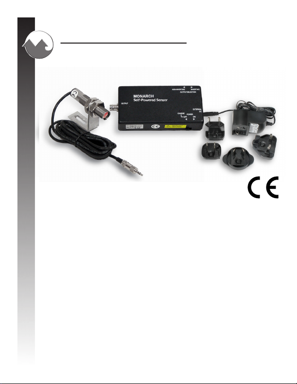
SPSR-115/230 Series - SPSR-IM with ROS-P
The SPSR-115/230 consists of the SPSR-IM Interface Module described
above, an ROS-P Remote Optical Sensor with eight foot cable and mounting
bracket, and an SPSR-U (115/230 Vac) external power connection. One foot
of T-5 Reective Tape is also supplied.
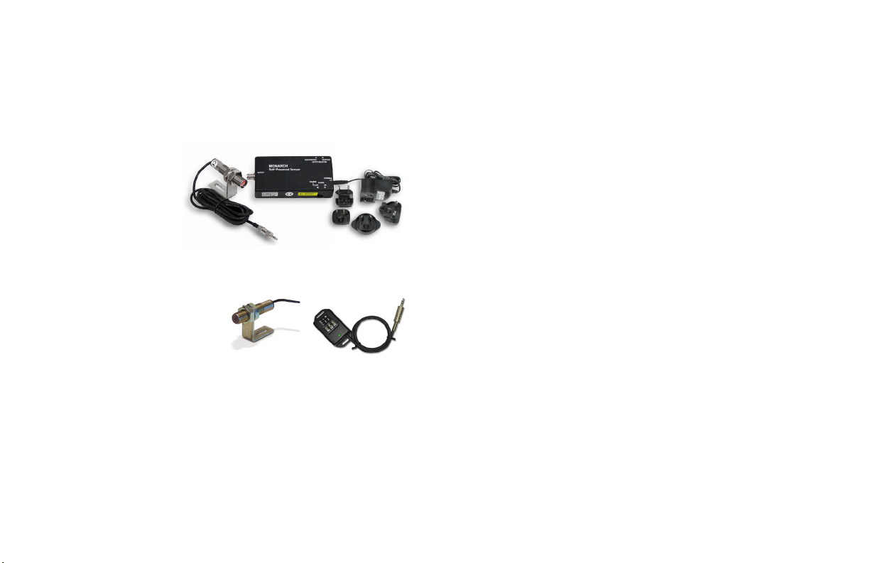
ROS-P
When connected to the SPSR-IM as described above, the ROS-P
illuminates the target with a visible red light from a high intensity LED
and detects the reected pulses from the rotating reective tape target
with an internal photo-detector. The ROS-P Remote Optical Sensor is
capable of detecting a reected pulse from T-5 Reective Tape targets
at distances of up to 3 feet and angles up to 45 degrees from the target.
The sensor is supplied with a set of two M16 jam nuts and a 90° angle
slotted aluminum mounting bracket.
4
For most applications, a 1/2” square piece of T-5 Reective Tape should
be applied to a clean area on the rotating object. The sensor should be
mounted and optically aligned to illuminate the reective target once per
revolution. It is recommended that the optical sensor be placed at a
slight angle (approximately 10-15 degrees) from perpendicular, so
that the sensor will detect only the reected pulses from the target.
The sensor should be at least 2 inches and no more than 3 feet from the
target. The green LED On-Target Indicator on the ROS-P will blink at
the input frequency or be continuously illuminated when properly aimed.
Operating the SPSR as a triggering source
Once the ROS-P input sensor is properly mounted and aligned, further
connections and operation should proceed in accordance with the
functions and descriptions under the SPSR Interface Module sections
entitled ‘Connections’ and ‘Controls’.
The pulse signal on the connector marked “Output” provides a sharp leading
edge for reliable and repeatable triggering of the connected device. This
output is capable of driving a hundred feet of coax cable. Be sure to select
the direction (0 to 5 Vdc or 5 to 0 Vdc) of this signal to provide the required
polarity of the leading edge to properly trigger the connected equipment.
BATTERY DISPOSAL
Prior to disposing of the SPSR-IM, the user must remove the Nickel Metal
Hydride batteries. To do this, remove the four (4) rubber feet on the bottom of
the unit. This will expose four (4) screws that must be removed to dismantle
the bottom case piece, exposing the batteries. Remove the batteries and place
tape over the battery terminals to prevent them from shorting. The batteries
should be sent to a recycling center or returned to the factory. The rest of
the parts may now be disposed of.
NOTE: This product contains Nickel Metal Hydride (NiMH) batteries.
Replace only with the same type of battery – Rechargeable NiMH.