manuals.online logo
Brands
  1. Home
  2. •
  3. Brands
  4. •
  5. Honeywell
  6. •
  7. Accessories
  8. •
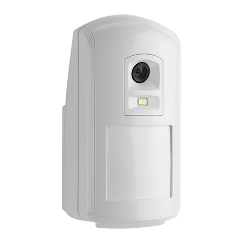
  9. Honeywell V-Plex IS2500SN User manual

Honeywell V-Plex IS2500SN User manual

IS2500SN V-PlexTM PIR Motion Sensor - Installation Instructions
1.8 - 2.7 m
(EN 2.0 - 2.3m)
(EN 2.3m)
2.3 - 2.4 m
LOCATION / LOCATIE / EMPLACEMENT / POSIZIONAMENTO / LOCALIZACIÓN / LOCALIZAÇÃO
1
Wide Angle Lens (installed)
Groothoeklens (geïnstalleerd)
Lentille grand angle (installée)
Lente grandangolare (installata)
Lente de abanico (instalada)
Lente Grande Angular (instalada)
Animal Immune Lens (included)
Lens voor negeren van dieren (meegeleverd)
Lentille immunité aux petits animaux (fournie)
Lente di immunità agli animali (inclusa)
Lente inmune a animales (incluida)
Lentes Imunidade a Animais (incluída)
WTTV- V+
OPEN / OPENEN / OUVERTURE / APERTURA / APERTURA / ABERTURA MOUNT / MONTAGE / INSTALLATION / MONTAGGIO / MONTAJE / MONTAGEM
3
5
6
2
WIRE / AANSLUITEN/ / CABLAGE / COLLEGAMENTO /
CABLEADO / LIGAÇÕES
IDENTIFY COMPONENTS AND SELECT APPROPRIATE SETTINGS / ONDERDELEN CONTROLEREN EN INSTELLINGEN SELECTEREN / IDENTIFICATION DES COMPOSANTS ET SÉLECTION DES
PARAMÈTRES APPROPRIÉS / IDENTIFICARE I COMPONENTI E SELEZIONARE LE IMPOSTAZIONI APPROPRIATE / IDENTIFICAR LOS COMPONENTES Y SELECCIONAR LA CONFIGURACIÓN
ADECUADA / IDENTIFICAR COMPONENTES E SELECCIONAR DEFINIÇÕES APROPRIADAS
1
Polling Loop
8 - 11V
PK - PK
SMB-10T
TAMPER
Cover Tamper Switch
Sabotageschakelaar
Contact AP du capot
Interruttore tamper sul
coperchio
Tamper de la cubierta
Interruptor de Tamper
da Tampa
3
2
WWith SMB10T
Met SMB10T
Avec SMB10T
Con SMB10T
Con SMB10T
Com SMB10T
REPLACE CIRCUIT BOARD / PRINTPLAAT TERUGPLAATSEN /
REMISE EN PLACE DU PCB / RIPOSIZIONARE IL CIRCUITO /
VOLVER A COLOCAR LA PLACA DE CIRCUITO IMPRESO /
SUBSTITUIÇÃO DE CIRCUITO IMPRESSO
4
a
0.2-1.3mm2
(24-16 AWG)
ON
OFF
123
TT+
-
W
LED
* Vedere il passaggio 7 -
Modalità Standard
Funzione Inibizione
traffico elevato OFF *
Funzione Inibizione
traffico elevato ON *
ON
OFF 1234
ON
OFF 1234
Pulse Count 2
Low Sensitivity
LED Disabled
Pulse Count 1
High Sensitivity
LED Enabled
High Traffic Inhibit OFF *
High Traffic Inhibit ON *
* See Step 7
- Standard Mode
Conteggio impulsi 2
Sensibilità bassa
LED disabilitato
Conteggio impulsi 1
Sensibilità alta
LED abilitato
- Rear Tamper Breakaway Tab;
Best
if mounted to a stud, solid wood,
or with a robust wall anchor.
- Antisabotage afbreeklipje aan achterzijde;
kan het best worden bevestigd aan een
spijker, in massief hout, of met een
stevige schroef en plug.
- Languette d'autoprotection à l'arrachement.
Le montage est plus fiable s'il est réalisé
sur un montant, un morceau de bois solide
ou avec une fixation murale robuste.
- Linguetta posteriore antimanomissione;
Meglio se montata su un asse di legno
solido o con un solido attacco a muro
.
- Tamper trasero: mejor si se monta en una tachuela,
una madera sólida o con un anclaje de pared fuerte.
- Separador Posterior de Quebra de Tamper; Melhor instalado num
rebite, madeira sólida ou com um gancho de fixação de parede robusto.
ON
OFF 12
Lowest Sensitivity: 3 - 5 Steps; Up to 36 kg Animal Immunity
Laagste gevoeligheid: 3 - 5 stappen; negeren van dieren tot 36 kg
Sensibilité minimale : 3 à 5 pas; immunité aux animaux jusqu'à 36 kg
Sensibilità bassissima: 3 - 5 passaggi; fino a 36 kg Immunità agli animali
Sensibilidad más baja: 3 a 5 pasos; inmunidad a animales de hasta 36 kg
Sensibilidade Mais Baixa: 3 - 5 Passos; Imunidade a animais até 36 kg
ON
OFF 12
Low Sensitivity: 2 - 4 Steps; Up to 18 kg Animal Immunity
Lage gevoeligheid: 2 - 4 stappen; negeren van dieren tot 18 kg
Sensibilité faible : 2 à 4 pas; immunité aux animaux jusqu'à 18 kg
Sensibilità bassa: 2 - 4 passaggi; fino a 18 kg Immunità agli animali
Sensibilidad baja: 2 a 4 pasos; inmunidad a animales de hasta 18 kg
Baixa Sensibilidade: 2 - 4 Passos; Imunidade a animais até 18 kg
ON
OFF 12
Medium Sensitivity: 1 - 3 Steps; No Animal Immunity
Gemiddelde gevoeligheid: 1 - 3 stappen; niet negeren van dieren
Sensibilité moyenne : 1 à 3 pas; aucune immunité aux animaux
Sensibilità media: 1 - 3 passaggi; senza immunità agli animali
Sensibilidad media: 1 a 3 pasos; sin inmunidad a animales
Sensibilidade Média: 1 - 3 Passos; Sem Imunidade a Animais
ON
OFF 12
High Sensitivity: 1 - 2 Steps; No Animal Immunity
Hoge gevoeligheid: 1 - 2 stappen; niet negeren van dieren
Sensibilité élevée : 1 à 2 pas; aucune immunité aux animaux
Sensibilità alta: 1 - 2 passaggi; senza immunità agli animali
Sensibilidad alta: 1 y 2 pasos; sin inmunidad a animales
Alta Sensibilidade: 1 - 2 Passos; Sem Imunidade a Animais
Look-Down Mask (install as shown when using Animal Immune Lens)
Kruipzone masker (installeren zoals aangegeven indien de
lens voor het negeren van dieren wordt gebruikt)
Masquage des faisceaux verticaux (à installer comme
indiqué dans le cas de l'utilisation d'une lentille immunité
aux petits animaux)
Maschera antistrisciamento (installare come mostrato quando
si utilizza l'obiettivo di immunità agli animali)
Máscara para ángulo 0º (instalar tal como se muestra cuando
se utilizan lentes inmunes a animales)
Máscara Look-Down (instale como mostrado quando utiliza as
Lentes Imunidade a Animais)
Inibição de Tráfego
Elevado DESLIGADO *
Inibição de Tráfego
Elevado LIGADO *
* Ver passo 7 -
Modo Standard
Inhibition de trafic élevé INACTIF
*
Inhibition de trafic élevé ACTIF *
* Voir étape 7 -
Mode Standard
Comptage d'impulsions 2
Sensibilité faible
Témoin lumineux à DEL désactivé
Comptage d'impulsions 1
Sensibilité élevée
Témoin lumineux à DEL activé
Contagem de Pulsos 2
Baixa Sensibilidade
LED Desactivado
Contagem de Pulsos 1
Alta Sensibilidade
LED Activado
ON
OFF 1234
ON
OFF 1234
Pulstelling 2
Lage gevoeligheid
LED uitgeschakeld
Pulstelling 1
Hoge gevoeligheid
LED ingeschakeld
Contador de pulsos 2
Sensibilidad baja
LED deshabilitado
Contador de pulsos 1
Sensibilidad alta
LED habilitado
ON
OFF 1234
ON
OFF 1234
Rem zwaar verkeer UIT *
Rem zwaar verkeer AAN *
* Zie Stap 7 -
Standaardmodus
Inhibidor de tráfico
intenso apagado *
Inhibidor de tráfico
intenso encendido *
* Véase el paso 7 -
Modo Standard
4
IS2500SN V-PlexTM PIR Motion Sensor - Installation Instructions
- Page 2 -
ENGLISH NEDERLANDS FRANÇAIS
bFOR ANIMAL IMMUNITY
•Mount the center of the sensor at 2.3 m – 2.4 m high. Do not use
optional swivel mount brackets.
•Set the sensor to the Lowest or Low sensitivity (see step 6a).
•Install Animal Immune lens (5-532-489-00 - see Lens Change
Instructions on page 2).
•Install the look-down mask (see Step 6a).
•Install the sensor where animals cannot come within 1.8 m of the
sensor by climbing on furniture or other objects.
•Aim the sensor away from stairways, furniture or other objects that
can be climbed on by animals.
•TEST the installation site to determine the exact level of attainable
animal immunity.
PROGRAM THE SENSOR
This sensor is a serial number device. Refer to the control panel’s
manual for instructions on registering devices and programming.
For all V-PlexTM panels, program the sensor Zone Type as INT
FOLLOWER 04 and the INPUT TYPE as “06” (for SL - Serial Polling
Device).
If using a Smart V-PlexTM panel, program the sensor to Standard mode
[press “0” (No)] or SMART CONTACT mode [press “1” (Yes)].
Standard Mode: The sensor includes a selectable High Traffic Inhibit
(HTI) feature. This feature reduces bus traffic with a randomized delay
(from 5 – 15 seconds) between alarm signals after an alarm and restoral
signal is sent. In applications where this delay is not necessary, set DIP
Switch 4 to OFF.
Smart Contact Mode: In the Smart Contact mode, the sensor
automatically reduces bus traffic by not sending alarm signals when
disarmed.
ALL modes: Tamper and self-test failures signals are sent without
delays.
LED OPERATION
The LED can be enabled in several ways:
−After power up mode the LED is enabled for 10 minutes (DIP switch 3
ON or OFF).
−Remove and replace the front cover to enable the LED for 10 minutes
(DIP switch 3 ON or OFF).
−Set DIP switch 3 ON (LED Enable); LED remains enabled until
disabled (switch 3 OFF). [Exception: When programmed to Smart
Contact mode and the system is armed, the LED is always disabled.]
−Remote LED Enable. [If using a Smart V-PlexTM panel, a Remote LED
Enable feature may be available, which allows remote enabling of the
LED if DIP switch 3 is OFF. (Refer to the Burglary Walk-Test section
in the control panel’s manual.) Using this method, the LED remains
enabled while the panel is in the burglary walk test mode.]
Power Up
Trouble Fast Blinking Red (LED Enabled
or Disabled)
Condition Indicator LED
Slow Blinking Red (only when LED is enabled)
[Finished within 60 seconds, typical]
Indicator LEDs
Walk Test Red ON for 3 seconds if Alarm
WALK TEST THE SENSOR
To walk test the sensor, enable the LED (see above).
Walk through the detection area and observe the LED. Refer to the LED
Indicator table, and if necessary, adjust the pulse count or sensitivity
setting.
TROUBLESHOOTING
RED LED flashing rapidly during normal operation indicates a trouble
condition. Either a PIR or temperature compensation fault is present.
Solution: Momentarily power down the sensor. If the trouble does not
clear, replace the sensor. (Please check the power, and all wiring before
replacing the sensor.)
bVOOR HET NEGEREN VAN DIEREN
•Plaats het midden van de sensor op een hoogte van 2,3 m – 2,4 m.
Gebruik de optionele draaibeugels niet.
•Stel de sensor in op Laagste of Lage gevoeligheid (zie stap 6a).
•Installeer de lens voor het negeren van dieren (5-532-489-00 - zie de
instructies voor het vervangen van lenzen op pagina 2).
•Installeer het kruipzone masker (zie stap 6a).
•Installeer de sensor op een plaats waar dieren niet binnen een straal
van 1,8 m. van de sensor kunnen komen door op meubels of andere
voorwerpen te klimmen.
•Richt de sensor niet op een trap, meubel of ander voorwerp waar
dieren op kunnen klimmen.
•TEST de locatie om precies te bepalen in hoeverre dieren genegeerd
kunnen worden.
DE SENSOR PROGRAMMEREN
Deze sensor is een serienummerapparaat. Raadpleeg de handleiding
van het inbraak alamrpaneel voor instructies voor het registreren en
programmeren van apparaten.
Stel voor alle V-PlexTM-panelen het zonetype in als INT FOLLOWER 04 en
kies bij INPUT TYPE (Invoertype) '06' (voor SL – Serial Polling Device).
Als u een Smart V-PlexTM-paneel gebruikt, selecteert u voor de sensor de
standaardmodus [druk op “0” (Nee)] of de modus SMART CONTACT [druk
op “1” (Ja)].
Standaardmodus: De sensor bevat de optionele functie HTI (Rem zwaar
verkeer) . Deze functie vermindert het busverkeer met een willekeurige
vertraging (tussen 5 en 15 seconden) tussen alarmsignalen nadat er een
alarm en een herstelsignaal zijn verstuurd. In toepassingen waarvoor
deze vertraging niet nodig is, stelt u DIP-schakelaar 4 in op UIT.
Smart Contact-modus: In de modus Smart Contact vermindert de sensor
automatisch busverkeer door geen alarmsignalen in uitgeschakelde
stand te verzenden.
ALL-modus: Signalen voor sabotage en mislukte zelftests worden zonder
vertraging verstuurd.
LED-BEDIENING
U kunt de LED op verschillende manieren inschakelen:
−Na het opstarten wordt de LED 10 minuten lang ingeschakeld (DIP-
schakelaar 3 AAN of UIT).
−Verwijder de voorzijde en plaats deze terug, waardoor de LED 10
minuten lang wordt ingeschakeld (DIP-schakelaar 3 AAN of UIT).
−Stel DIP-schakelaar 3 in op AAN (LED ingeschakeld). De LED blijft
ingeschakeld totdat deze wordt uitgeschakeld (schakelaar 3 UIT).
[Uitzondering: wanneer de Smart Contact-modus is ingeschakeld en
het systeem is geactiveerd, is de LED altijd uitgeschakeld.]
−LED op afstand activeren. [LED activatie op afstand kan beschikbaar
zijn als u een Smart V-PlexTM paneel gebruikt, waardoor de LED
geactiveerd kan worden onafhankelijk van de instelling van DIP
switch 3. (Zie de looptest sectie in de handleiding van het paneel) Op
deze manier blijft de LED geactiveerd tijdens delooptest.]
Opstarten
Problemen Snel rood knipperend (LED ingeschakeld of
uitgeschakeld)
Toestand Indicator-LED
Langzaam rood knipperend (Alleen wanneer LED is
ingeschakeld) [Meestal binnen 60 seconden voltooid]
Indicator-LED's
Looptest Rood AAN gedurende 3 seconden in geval
van alarm
LOOPTEST SENSOR
Schakel de LED in (zie hierboven).
Loop door het detectiegebied en kijk naar de LED. Raadpleeg de LED-
indicatietabel en stel indien nodig de puls-count of de gevoeligheid bij.
PROBLEMEN OPLOSSEN
De RODE LED knippert tijdens normaal bedrijf snel om een probleem
aan te geven. Er is een probleem met de PIR-detectie of met de
temperatuurcompensatie.
Oplossing: Schakel de sensor even uit. Lost dit de problemen niet op,
vervang dan de sensor. (Controleer de stroomtoevoer en alle bedrading
voordat u de sensor vervangt.)
bPOUR L’IMMUNITÉ AUX ANIMAUX
•Monter le centre du détecteur à une hauteur de 2,30 m – 2,40 m. Ne
pas utiliser les fixations à rotule optionnelles.
•Régler le détecteur à la sensibilité minimale ou faible (voir l’étape 6a).
•Installer la lentille immunité aux petits animaux (5-532-489-00 – voir la
procédure de remplacement de la lentille page 2).
•Installer le masque des faisceaux verticaux (voir l’étape 6a).
•Installer le détecteur en prévoyant un rayon de 1,80 m autour de
celui-ci où les animaux ne peuvent pas pénétrer en grimpant sur un
meuble ou tout autre objet.
•Placer le détecteur à l’écart d’un escalier, d’un meuble ou de tout
autre objet sur lequel un animal pourrait monter.
•TESTER l’emplacement d’installation pour déterminer le niveau exact
possible d'immunité aux animaux.
PROGRAMMER LE DÉTECTEUR
Ce détecteur dispose d'un numéro de série. Se reporter au manuel de la
centrale d'alarme pour obtenir les instructions sur l’enregistrement des
dispositifs et la programmation.
Pour toutes les centrales V-PlexTM, programmer INT FOLLOWER 04
comme type de zone (Zone Type) du détecteur et « 06 » comme
« INPUT TYPE » (pour SL (dispositif muni d'un numéro de série).
Si une centrale compatible Smart V-PlexTM est utilisée, programmer le
détecteur en mode Standard [appuyer sur « 0» (non)] ou en mode
SMART CONTACT [appuyer sur « 1» (oui)].
Mode Standard : Le détecteur comporte une fonction d’inhibition de trafic élevé
(
High Traffic Inhibit
- HTI) sélectionnable. Cette fonction réduit le trafic sur le bus
en introduisant un retard aléatoire (entre 5 et 15 secondes) entre les signaux
d'alarme après l'envoi d'un signal d’alarme et de rétablissement. Pour les
applications pour lesquelles ce retard n’est pas nécessaire, définissez le
commutateur DIP 4 sur OFF (INACTIF).
Mode Smart Contact : En mode Smart Contact, le détecteur réduit
automatiquement le trafic du bus en n’envoyant pas de signaux d’alarme
lorsque la centrale d'alarme est désarmée.
Tous les modes : Les signaux d’autoprotection et d’échec de l’auto-test
sont envoyés sans retard.
FONCTIONNEMENT DE LA LED
La LED peut être activée de plusieurs manières :
−Après la mise sous tension, la LED est activée pendant 10 minutes
(commutateur DIP 3 sur ON ou OFF).
−Oter et remettre le capot avant pour activer la LED pendant
10 minutes (commutateur DIP 3 sur ON ou OFF).
−Placer le commutateur DIP 3 sur ON (LED Activée) ; la LED reste activée
jusqu’à ce qu'elle soit désactivée (commutateur 3 sur OFF). [Exception : la
LED est toujours désactivée lorsque le détecteur est programmé en mode
Smart Contact et que le système est en service.]
−Activation de la LED à distance. [Si une centrale compatible Smart V-
PlexTM est utilisée, une fonction d’activation de la LED à distance est
éventuellement disponible, ce qui permet d’activer la LED
indépendamment du commutateur DIP 3. Cette méthode permet de
conserver la LED activée jusqu’à ce qu'elle soit désactivée à distance.]
Mise sous tension
Panne Clignotement rapide en rouge (témoin lumineux à
DEL activé ou désactivé)
Condition Indicateur à témoin lumineux (DEL)
Rouge à clignotement lent (Uniquement quand la LED
est activée) [terminé dans les 60 secondes en général]
Indicateurs à témoins lumineux (DEL)
Test de Déplacement ALLUMÉ en rouge pendant 3 secondes en cas
d'alarme
TEST DE DÉTECTION
Activez la LED (voir ci-dessus).
Se déplacer dans la zone de couverture et observer la LED. Se reporter
au tableau des indications de la LED, et, si nécessaire, régler le nombre
d’impulsions ou la sensibilité.
DÉPANNAGE
Un VOYANT ROUGE qui clignote rapidement en fonctionnement normal
indique un problème. Il s’est produit une erreur IRP ou de compensation
de température.
Solution : Mettez temporairement le détecteur hors tension. Si le
problème persiste, remplacez le détecteur. (Vérifiez l'alimentation ainsi
que tous les câblages avant de remplacer le détecteur.)
LENS CHANGE INSTRUCTIONS / INSTRUCTIES VOOR HET VERVANGEN VAN LENZEN / INSTRUCTIONS DE REMPLACEMENT DE LA LENTILLE /
ISTRUZIONI PER IL CAMBIO DELL'OBIETTIVO / INSTRUCCIONES DE CAMBIO DE LENTES / INSTRUÇÕES PARA MUDANÇA DE LENTES
DETECTION PATTERNS / DETECTIEPATRONEN / COUVERTURE DE DETECTION /
DIAGRAMMA DI COPERTURA / PATRON DE DETECCIÓN / PADRÕES DE DETECÇÃO
15m Wide Angle Lens / Groothoeklens / Lentille grand angle / Lente grandangolare /
Lente de abanico / Lente Grande Angular (P/N 5-532-439-00 – Installed)
Top View / BOVENAANZICHT / VUE DE DESSUS / Vista in pianta / VISTA DESDE ARRIBA / Vista Superior
Side View
/
ZIJAANZICHT / VUE DE COTE / Vista in
sezione / VISTA LATERAL / Vista Lateral
LENS MASKING / LENSBLOKKERING / MASQUAGE DE LA LENTILLE
/ MASCHERAMENTO DELL'OBIETTIVO / ENMASCARAMIENTO DE
LENTES / EMASCARAMENTO DE LENTES
5-532-439-00
TOP
50FT
IS2500SN V-PlexTM PIR Motion Sensor - Installation Instructions
- Page 3 -
ITALIANO ESPAÑOL PORTUGUÊS
bPER L'IMMUNITÀ AGLI ANIMALI
•Montare la parte centrale del sensore a un'altezza di 2,3 m – 2,4 m. Non
utilizzare staffe di montaggio orientabili opzionali.
•Impostare il sensore alla sensibilità bassa o bassissima (vedere passo 6a).
•Installare l'obiettivo di immunità agli animali (5-532-489-00 - vedere le
istruzioni sul cambio di obiettivo a pagina 2).
•Installare la maschera antistrisciamento (vedere passo 6a).
•Installare il sensore in un punto in cui gli animali pur scavalcando mobili o
altri oggetti restino a 1,8 m dal sensore.
•Puntare il sensore lontano da scale, mobili o altri oggetti sui quali gli
animali possono arrampicarsi.
•Effettuare un TEST del luogo di installazione per determinare il livello
esatto di immunità agli animali raggiungibile.
PROGRAMMAZIONE DEL SENSORE
Questo sensore è un dispositivo dotato di numero di serie. Per le
istruzioni sulla registrazione dei dispositivi e la programmazione, fare
riferimento al manuale della centrale di controllo.
Per tutte le centrali V-PlexTM, programmare il tipo di zona del sensore su
INTERNA (ZT=04) e il TIPO DI INGRESSO su “06” (per SL, ovvero
dispositivo di polling seriale).
Se si utilizza una centrale compatibile Smart V-PlexTM, scegliere se
programmare il sensore con modalità Standard [premere “0” (No)]
oppure con modalità SMART [premere “1” (Sì)].
Modalità Standard - Il sensore comprende una funzione Inibizione
traffico elevato (HTI) selezionabile. Questa funzione riduce il traffico sul
bus con l’introduzione di un ritardo random (da 5 a 15 secondi) dopo
l'invio di un segnale di allarme e ripristino. Nelle applicazioni in cui
questo ritardo non è necessario, impostare l'interruttore DIP 4 su OFF.
Modalità Smart Contact - Nella modalità Smart Contact il sensore riduce
automaticamente il traffico sul bus non inviando i segnali di allarme
quando il sistema è disinserito.
TUTTE le modalità - I segnali di manomissione e autotest fallito (guasto)
vengono inviati senza ritardi.
FUNZIONAMENTO DEL LED
Il LED può essere abilitato in vari modi:
−Dopo la modalità accensione il LED viene abilitato per 10 minuti
(interruttore DIP 3 su ON o OFF).
−Rimuovere e riposizionare il coperchio frontale per abilitare il LED per
10 minuti (interruttore DIP 3 su ON o OFF).
−Impostare l'interruttore DIP 3 su ON (LED abilitato); il LED rimane
abilitato fino a quando non viene disabilitato (interruttore 3 su OFF).
[Eccezione: quando il sistema è inserito ed è programmata la
modalità Smart Contact, il LED è sempre disabilitato].
−Abilitazione remota LED [se si utilizza una centrale Smart V-PlexTM,
è disponibile una funzione di abilitazione remota LED (es. funzione di
TEST) indipendente dall'impostazione dell'interruttore DIP 3. Riferirsi
alla sezione Walk Test (prova sensori) della centrale di sicurezza per
maggiori dettagli. Se si utilizza questo metodo, il LED rimane abilitato
durante il test fino a quando non viene disabilitato dalla centrale a
seguito del termine della sessione di test].
Accensione
Guasto Lampeggiamento rapido di colore rosso (LED abilitato
o disabilitato)
Condizione LED
Lampeggiamento lento di colore rosso (Solo quando il
LED è abilitato) [in genere termina entro 60 secondi]
LED
Walk Test Acceso di colore rosso per 3 secondi in caso di allarme
WALK TEST DEL SENSORE
Abilitare il LED (vedere sopra).
Camminare nell'area di rilevamento e osservare il LED. Fare riferimento
alla tabella delle indicazioni del LED e, se necessario, regolare il
conteggio degli impulsi o l'impostazione della sensibilità.
DIAGNOSTICA
Il LED ROSSO che lampeggia rapidamente durante il normale
funzionamento indica una condizione di guasto. Si è verificato un guasto
a livello di PIR o di compensazione della temperatura.
Soluzione: spegnere per un attimo il sensore. Se il problema non viene
risolto, sostituire il sensore. (Verificare l'alimentazione e il cablaggio
prima di procedere alla sostituzione.)
bPARA INMUNIDAD A ANIMALES
•Monte el centro del sensor a 2,3 m – 2,4 m de altura. No utilice rótulas
opcionales.
•Ponga el sensor en la sensibilidad más baja o en la sensibilidad baja
(vea al paso 6a).
•Instale la lente inmune a animales (5-532-489-00: consultar las
instrucciones sobre el cambio de lentes en la página 2).
•Instale la máscara para el ángulo 0º (consultar el paso 6a).
•Instale el sensor en un lugar al que los animales no puedan llegar a
una distancia de 1,8 m del mismo, trepando por los muebles u otros
objetos.
•Sitúe el sensor lejos de escaleras, muebles u otros objetos a los que
puedan trepar los animales.
•PRUEBE el lugar de instalación para determinar el nivel exacto de
inmunidad a animales que se puede alcanzar.
PROGRAME EL SENSOR
Este sensor es un dispositivo con número de serie. Consulte el manual
del panel de control para obtener información sobre cómo registrar
dispositivos y programarlos.
En todos los paneles V-PlexTM, programe el sensor Zone Type como INT
FOLLOWER 04 e "INPUT TYPE" como “06” (para el dispositivo de
número serie SL).
Si utiliza un panel Smart V-Plex™, programe el sensor con el modo
Standard [pulse “0” (No)] o el modo SMART CONTACT [pulse “1” (Sí)].
Modo Standard: El sensor incluye una función con la que se puede seleccionar el
inhibidor de tráfico intenso (HTI, High Traffic Inhibit). Esta función reduce el tráfico
del bus con un retraso aleatorio (entre 5 y 15 segundos) entre las señales de
alarma tras enviar una alarma y señal de restablecimiento. En las aplicaciones
donde no sea necesario un retraso, deje el conmutador DIP 4 en OFF.
Modo Smart Contact: En el modo Smart Contact, el sensor reduce
automáticamente el tráfico del bus al no enviar señales de alarma
cuando el sistema está desarmado.
En todos los modos: Se envían las señales de tamper y fallos de auto-
test sin retrasos.
FUNCIONAMIENTO DEL LED
Se puede activar el LED de diferentes maneras:
−Tras el modo de encendido se activa el LED durante 10 minutos
(conmutador DIP 3 en ON o en OFF).
−Retire y vuelva a colocar la tapa frontal para activar el LED durante
10 minutos (interruptor DIP 3 en ON o en OFF).
−Cambie el conmutador DIP 3 a ON (activar LED); el LED
permanecerá activado hasta que se desactive (conmutador 3 en
OFF). [Excepción: Cuando está programado el modo Smart Contact y
el sistema está armado, el LED siempre está desactivado.]
−Activación remota de LED. [Si utiliza un panel Smart V-PlexTM, puede
que esté disponible la función Remote LED Enable (Activación
remota de LED), que activa el LED con independencia de la posición
del conmutador DIP 3. Con este método, el LED permanece activo
hasta que se desactiva remotamente.]
Encendido
Problemas Parpadeo rápido en rojo (LED habilitado o
deshabilitado)
Condición Indicador LED
Parpadeo lento en rojo (Sólo cuando está activado
el LED) [suele durar 60 segundos]
Indicadores LED
Test de Paseo Rojo ON durante 3 segundos si hay alarma
TEST DE PASEO
Habilite el LED (consulte más arriba).
Recorra la zona de detección y observe el LED. Consulte la tabla del
indicador LED y, si fuera necesario, ajuste el recuento de impulsos o la
sensibilidad.
RESOLUCIÓN DE PROBLEMAS
Un LED ROJO parpadeando rápidamente durante el funcionamiento
normal indica un problema. Se ha producido un fallo en el PIR o de
compensación de temperatura.
Solución: Apague momentáneamente el sensor. Si el problema no
desaparece, sustituya el sensor. (Compruebe la alimentación eléctrica y
todo el cableado antes de sustituir el sensor.)
bPARA IMUNIDADE A ANIMAIS
•Monte o centro do sensor a uma altura de 2,3 m – 2,4 m. Não utilize
suportes articulados opcionais.
•Defina o sensor para a Sensibilidade Mais Baixa ou Baixa (consulte o
passo 6a).
•Instale as lentes de Imunidade a Animais (5-532-489-00 – consulte as
Instruções de Mudança de Lentes na página 2).
•Instale a máscara look-down (consulte o Passo 6a).
•Instale o sensor num local em que os animais não se possam
aproximar a 1,8 m deste subindo a mobília ou outros objectos.
•Não aponte o sensor para escadas, mobília ou outros objectos aos
quais os animais possam subir.
•TESTE o local da instalação para determinar o nível exacto de
imunidade a animais possível.
PROGRAMAR O SENSOR
Este sensor é um dispositivo com número de série. Consulte o manual
da central de detecção para obter instruções de registo de dispositivos e
programação.
Para todas as centrais V-PlexTM, programe o campo “ZONE TYPE” do
sensor como INT FOLLOWER 04 e ”INPUT TYPE” como “06” [para SL -
Serial Polling Device (Dispositivo de laço)].
Se utilizar uma central Smart V-PlexTM, programe o sensor no modo Standard
[prima “0” (Não)] ou no modo SMART CONTACT [prima “1” (Sim)].
Modo Standard: O sensor inclui uma funcionalidade de Inibição de
Tráfego Elevado (HTI - High Traffic Inhibit) programável. Esta
funcionalidade reduz o tráfego no bus de comunicações com um atraso
aleatório (de 5 a 15 segundos) entre sinais de alarme após o envio de
um sinal de alarme e de reposição. Em aplicações onde este atraso não
seja necessário, configure o interruptor DIP 4 como OFF (DESLIGADO).
Modo Smart Contact (Contacto Inteligente): No modo Smart Contact, o
sensor reduz automaticamente o tráfego no bus de comunicações
anulando o envio de sinais de alarme com o sistema desarmado.
TODOS os modos: As falhas de tamper e auto-teste são enviados sem
atraso.
FUNCIONAMENTO DO LED
O LED pode ser activado de diversas formas:
−Após o modo de iniciação, o LED fica activado durante 10 minutos
[interruptor DIP 3 ON (LIGADO) ou OFF (DESLIGADO)].
−Remova e coloque novamente a tampa frontal para activar o LED durante
10 minutos [interruptor DIP 3 ON (LIGADO) ou OFF (DESLIGADO)].
−Configure o interruptor DIP 3 como ON (LIGADO) (LED Activado); o LED
permanece activado até o desactivar [interruptor 3 OFF (DESLIGADO)].
[Excepção: Quando programado para o modo Smart Contact e com o
sistema armado, o LED fica sempre desactivado.]
−Activação de LED Remota. Se utilizar uma central Smart V-PlexTM, poderá estar
disponível uma funcionalidade de Activação de LED Remota, que activa o LED
independentemente da definição do interruptor DIP 3. Utilizando este método, o
LED permanece activado (até ser desactivado remotamente).
Iniciação
Problema Vermelho a Piscar Rapidamente (LED Activado ou
Desactivado)
CondiçãoIndicador LED
Vermelho a Piscar Lentamente (Apenas quando o LED
estiver activado) [terminado dentro de 60 segundos, típico]
Indicadores LED
Teste de
Caminhada Vermelho LIGADO por 3 segundos em caso de Alarme
TESTE DE CAMINHADA DO SENSOR
Active o LED (consulte acima).
Caminhe pela área de detecção e observe o LED. Consulte a tabela do
Indicador LED e, se necessário, ajuste a definição de contagem de
pulsos ou sensibilidade.
RESOLUÇÃO DE PROBLEMAS
LED VERMELHO a piscar rapidamente durante o funcionamento normal
indica um problema. Existe uma falha de PIR ou compensação de
temperatura.
Solução: Desligue momentaneamente o sensor. Se o sensor não
limpar, substitua-o. (Por favor verifique a alimentação e todos os cabos
antes de substituir o sensor.)
DETECTION PATTERNS / DETECTIEPATRONEN / COUVERTURE DE DETECTION /
DIAGRAMMA DI COPERTURA / PATRON DE DETECCIÓN / PADRÕES DE DETECÇÃO
11m Animal Immune Lens / Lens voor negeren van dieren / Lentille immunité aux petits animaux /
Lente di immunità agli animali / Lente inmune a animales / Lentes Imunidade a Animais (P/N 5-532-489-00 – Included)
Top View / BOVENAANZICHT / VUE DE DESSUS / Vista in pianta / VISTA DESDE ARRIBA / Vista Superior
27 m Optional Long Range Lens / Optionele Lens Voor Groot Bereik / Lentille Longue Portée, En Option / Lente a Lungo Raggio Opzionale / Lentes de Largo Alcance Opcionales /
Lentes de Longo Alcance Opcionais (P/N DT7000-LRLK)
Top View / BOVENAANZICHT / VUE DE DESSUS / Vista in pianta / VISTA DESDE ARRIBA /
Vista Superior
LENS MASKING / LENSBLOKKERING / MASQUAGE DE LA LENTILLE
/ MASCHERAMENTO DELL'OBIETTIVO / ENMASCARAMIENTO DE
LENTES / EMASCARAMENTO DE LENTES
5-532-489-00
TOP
25 / 35FT
Side View
/
ZIJAANZICHT / VUE DE COTE / Vista
in sezione / VISTA LATERAL / Vista Lateral
Install Look Down Mask to block look down zones.
Plaats een neerwaarts masker om neerwaartse zones te blokkeren.
Installez le masque de détection des faisceaux verticaux.
Installare la maschera di rilevamento verso il basso per bloccare il rilevamento delle zone in basso.
Instale una máscara de ángulo 0º para bloquear las zonas de vigilancia inferior.
Instale a Máscara Look Down para anular zonas de vigilância inferior.
Side View
/
ZIJAANZICHT / VUE DE COTE / Vista in sezione / VISTA LATERAL
/
Vista Lateral
= EN 50131-2-2
IS2500SN V-PlexTM PIR Motion Sensor - Installation Instructions
- Page 4 -
ENGLISH NEDERLANDS FRANÇAIS ITALIANO ESPAÑOL PORTUGUÊS
SPECIFICATIONS SPECIFICATIES CARACTERISTIQUES SPECIFICHE TECNICHE ESPECIFICACIONES ESPECIFICAÇÕES
Range: 15 m x 18 m [installed];
11 m x 12 m [included]; Optimum
mounting height for both lenses is
2.3 m
Bereik: 15 m x 18 m [geïnstalleerd];
11 m x 12 m [meegeleverd]; De
optimale montagehoogte voor
beide lenzen is 2,3 m
Couverture: 15 m x 18 m [installé];
11 m x 12 m [inclus]; La hauteur de
montage optimale pour les deux
objectifs est de 2,30 m
Portata: 15 m x 18 m [installato];
11 m x 12 m [incluso]; L'altezza di
montaggio ottimale per entrambi gli
obiettivi è pari a 2,3 m
Covertura: 15 m x 18 m [instalada];
11 m x 12 m [incluida]; Altura óptima
de montaje para ambas lentes 2,3 m
Alcance: 15 m x 18 m
[instalado]; 11 m x 12 m
[incluído]; Altura ideal de
montagem de ambas as lentes é
2.3 m
Tamper Switches: (NC)
10 mA, 24 VDC
Sabotage Schakelaar: (NC) 10
mA, 24 VDC
Autoprotection: (NC) 10 mA,
24 VDC
Interruttori antimanomissione:
(NC) 10 mA, 24 VDC
Salida de tamper: (NC) 10 mA,
24 VDC
Interruptor de Tamper: (NF)
10 mA, 24 VDC
Power Requirements: 8 - 11 V
PK - PK at polling loop terminals,
with reverse polarity protection
Voeding: 8 - 11 V PK - PK bij
uiteinden pollinglus, met
bescherming tegen omgekeerde
polariteit
Alimentation: 8 - 11 V PK - PK sur
les bornes du bus V-Plex, avec
protection contre l’inversion des
polarités
Alimentazione : 8 - 11 V PK - PK ai
terminali dei circuiti di polling, con
protezione dall'inversione di polarità
Requerimientos de alimentación:
8 - 11 V PK - PK en los terminales
polling loop, con protección contra la
polaridad invertida
Requisitos de Alimentação:
8 - 11 V PK - PK nos terminais de
pesquisa de ciclos, com protecção
contra polaridade inversa
Current:
LED ON (In Alarm) = 4.7 mA typical
LED OFF (Quiescent) = 1.6 mA
typical
Huidig:
LED AAN (In Alarm) = 4.7 mA normaal
LED UIT (Slapend) = 1.6 mA normaal
Consommation : LED ON (alarme en
cours) = 4,7 mA typique
LED OFF (repos) = 1,6 mA typique
Corrente: LED acceso (condizione di
allarme) = 4,7 mA nominale
LED spento (condizione di quiescenza)
= 1,6 mA nominale
Consumo: LED ENCENDIDO (En
alarma) = 4,7 mA típico
LED APAGADO (Inactivo) = 1,6 mA
típico
Corrente: LED ON (Em alarme) =
4.7 mA típico; LED OFF
(Repouso) = 1.6 mA típico
PIR White Light Immunity: 6,500
Lux typical
PIR Wit Licht Immuniteit: 6,500
Lux typisch
Immunité à la lumière blanche:
6,500 Lux Typique
Immunita PIR alla luce bianca:
6,500 Lux tipica
Immunidad contra luces blancas:
6,500 Lux típica
Imunidade PIR a Luz Branca:
6,500 Lux típico
Operating Temperature: -20° to
55° C, 5% - 95% relative humidity
(non-condensing)
Werkingstemperatuur: -20° tot
55° C, Relatieve Vochtigheid: 5%
- 95%, niet-condenserend
Température de fonctionnement:
-20° à 55° C; Humidité relative: 5%
à 95% sans condensation
Temperatura di esercizio: da -20°
a 55° C; 5% - 95% umidità relative
(non-condensansante)
Temperatura de funcionamiento:
-20° to 55° C; Humedad relativa: 5%
to 95% sin condensación
Temperatura de Funcionamento:
-20° a 55° C, 5% - 95% humidade
relativa (sem condensação)
Self-Tests:
End-to-End PIR self-test;
Temperature Compensation
Zelftests:
Volledige zelftest PIR;
Temperatuurcompensatie
Auto-Tests: Auto-test IRP (la totalité
du circuit); Compensation en
température
Auto-Tests: Supervisione
Microonda; Auto-test PIR end-to-
end; Comp. Temperatura
Auto-Test:
Autoprueba integral del PIR; Comp.
Temp.
Auto-Testes: Auto-teste End-to-
End (de todo) PIR; Compensação
de Temperatura
Temperature Compensation:
Advanced Dual Slope
Temperatuur Compensatie:
Intelligent (“Dual Slope”)
Compensation en température: A
double pente
Compensazione Temperatura:
Avanzata a doppio gradiente
Compensación de temperatura:
Doble pendiente avanzada
Compensação de
Temperatura: Declive Duplo
Avançado
PIR Fields of View:
Wide Angle Lens
(P/N 5-532-439-00)
44 long range zones
12 intermediate zones
6 lower zones
4 look-down zones
Animal Immune Lens
(P/N 5-532-489-00)
44 long range zones
36 intermediate zones
18 lower zones
4 look-down zones
PIR Velden:
Groothoeklens
(P/N 5-532-439-00)
44 lang bereik zones
12 midden
6 laag
4 kruipzones
Lens voor negeren van dieren
(P/N 5-532-489-00)
44 lang bereik zones
36 midden
18 laag
4 kruipzones
Champ de détection IRP:
Lentille grand angle
(P/N 5-532-439-00)
44 faisceaux longs
12 intermediaires
6 courts
4 verticaux
Lentille immunité aux petits animaux
(P/N 5-532-489-00)
44 faisceaux longs
36 intermediaires
18 courts
4 verticaux
Zone PIR:
Lente grandangolare
(P/N 5-532-439-00)
44 lunga portata
12 intermedie
6 inferiori
4 antistrisciamento
Lente di immunità agli animali
(P/N 5-532-489-00)
44 lunga portata
36 intermedie
18 inferiori
4 antistrisciamento
Zonas de detección:
Lente de abanico
(P/N 5-532-439-00)
44 zonas de largo alcance
12 zonas intermedias
6 zonas de corto alcance
4 zonas de ángulo 0º
Lente inmune a animales
(P/N 5-532-489-00)
44 zonas de largo alcance
36 zonas intermedias
18 zonas de corto alcance
4 zonas de ángulo 0º
Campos de Vista PIR:
Lentes Grande Angular
(P/N 5-532-439-00)
44 zonas de longo alcance
12 zonas intermédias
6 zonas mais baixas
4 zonas de vigilância inferior
Lentes Imunidade a Animais
(P/N 5-532-489-00)
44 zonas de longo alcance
36 zonas intermédias
18 zonas mais baixas
4 zonas de vigilância inferior
Dimensions:
12.5cm x 7.5cm x 4.3cm
Afmetingen:
12.5cm x 7.5cm x 4.3cm
Dimensions:
12.5cm x 7.5cm x 4.3cm
Dimensioni:
12.5cm x 7.5cm x 4.3cm
Dimensiones:
12.5cm x 7.5cm x 4.3cm
Dimensões:
12.5cm x 7.5cm x 4.3cm
Weight: 117.0 g (4.13 oz)
Packaged: 174.0 g (6.14 oz)
Gewicht: 117.0 g
Verpakt produkt: 174.0 g
Masse: 117.0 g
Emballé: 174.0 g
Peso: 117.0 g
Impachettato: 174.0 g
Peso: 117.0 g
Embalaje del producto: 174.0 g
Peso: 117.0 g
Embalado: 174.0 g
APPROVAL LISTINGS / KEURINGEN / AGREMENT / OMOLOGAZIONI / HOMOLOGACIONES / LISTA DE APROVAÇÕES
•CE
•EN 50131-1 and EN 50131-2-2 Security Grade 2, Environmental Class II.
•EN 50131-1 en EN 50131-2-2 Security Grade 2; Environmental Class II.
•EN 50131-1 et EN 50131-2-2, grade 2, classe enironnementale II.
•EN 50131-1 e EN 50131-2-2 Grado di Sicurezza 2; Classe Ambientale II.
•EN50131-1 y EN 50131-2-2 Grado de Seguridad 2, Clase Ambiental II.
•EN 50131-1 e EN 50131-2-2 Categoria de Segurança 2, Classe Ambiental II.
COMPLIANCE NOTES
•For EN 50131-2-2 compliant installations: set pulse count to 1, set
sensitivity to High, and install cover screw. Mount the sensor from 2.0 –
2.3m with Wide Angle Lens [P/N 5-532-439-00] or at 2.3m with Animal
Immune Lens [P/N 5-532-489-00]. See section 6b for animal immunity
requirements.
•Suitable for connection to an EN60950 Class II Limited Power Source in
European installations.
•Sensor must have a clear line-of-site to the protected area.
CERTIFICATIE RICHTLIJNEN
•Voor installaties die voldoen aan EN 50131-2-2: stel de pulstelling in op 1,
stel de gevoeligheid in op Hoog en plaats de schroef op de afdekkap.
Plaats de sensor op een hoogte van 2,0 - 2,3 m. met een groothoeklens
[P/N 5-532-439-00] of op 2,3 m. met een lens voor het negeren van dieren
[P/N 5-532-489-00]. Zie sectie 6b voor de vereisten met betrekking tot het
negeren van dieren.
•Geschikt voor aansluiting op een EN 60950 Class II Voeding in Europese
installaties.
•Zicht van de melder op het te bewaken gebied moet vrij van obstakels zijn.
NOTES DE CONFORMITÉ
•Pour les installations conformes à la norme EN 50131-2-2 : Fixez le
comptage d’impulsions à 1, la sensibilité sur la valeur « High » (élevée) et
installez la vis de capot. Montez le détecteur à une hauteur comprise entre
2,00 m et 2,30 m avec la lentille grand-angle [Réf 5-532-439-00] ou à
2,30 m pour la lentille immunité aux petits animaux [Réf 5-532-489-00].
Consultez la section 6b pour les critères d’immunité à la présence
d’animaux.
•Compatible pour un raccordement à une alimentation régulée EN 60950
Classe II.
•Le détecteur doit avoir une vue sans obstacle de la zone à protéger.
NOTE DI CONFORMITA’
•Per le installazioni conformi a EN 50131-2-2: impostare il
conteggio degli impulsi su 1, impostare la sensibilità su Alta e
installare la vite del coperchio. Montare il sensore a un'altezza
compresa tra 2,0 - 2,3 m con obiettivo grandangolare [N/P 5-
532-439-00] a 2,3 m con obiettivo di immunità agli animali [N/P
5-532-489-00]. Per i requisiti sull'immunità agli animali, vedere
la sezione 6b.
•Per connessioni con alimentatori compatibili EN 60950 Classe II in
contesto EU.
•Tra il sensore e l’area che si desidera proteggere non devono esserci
ostacoli.
NOTAS DE CONFORMIDAD
•Para instalaciones que cumplen EN 50131-2-2: programar el
contador de pulsos en 1, establecer la sensibilidad en Alta y
colocar tornillos en la cubierta. Monte el sensor a una altura de
2,0 a 2,3 m con la lente de abanico [N/P 5-532-439-00] o a una
altura de 2,3 m con la lente inmune a animales [N/P 5-532-489-00].
Consultar requisitos para inmunidad a animales en la sección 6b.
•Adecuado para conectarlo con una fuente de alimentación
EN60950 Clase II en instalaciones Europeas.
•El detector debe tener una visión clara del área que protege.
NOTAS DE CONFORMIDADE
•Para instalações em conformidade com a norma EN 50131-2-2:
defina a contagem de pulsos para 1, defina a sensibilidade
para Alta e instale o parafuso da tampa. Monte o sensor a 2,0
– 2,3m com Lentes de Grande Angular [P/N 5-532-439-00] ou a
2,3m com Lentes Imunes a Animais [P/N 5-532-489-00].
Consulte a secção 6b para informações sobre requisitos de
imunidade a animais.
•Adequado para conexão a uma Fonte de Alimentação Limitada
EN60950 Classe II em instalações europeias.
•O sensor tem de ter uma linha de visão desobstruída para a
área protegida.
To obtain applicable EU compliance Declaration of Conformities for this product, please refer to our Website,
http://www.security.honeywell.com/hsce/international/index.html. For any additional information regarding
the compliance of this product to any EU specific requirements, please contact:
De EU conformiteitsverklaring voor dit product kunt u vinden op
http://www.security.honeywell.com/hsce/international/index.html. Voor elke andere informatie betreffende de
conformiteit van dit product betreffende specifieke EU eisen dient u contact op te nemen met:
Les déclarations de conformité aux normes Européennes de ce produit sont disponibles sur notre site Internet
à l’adresse http://www.security.honeywell.com/hsce/international/index.html. Toutes informations
complémentaires relatives à la conformité de ce produit à des normes Européennes particulières peuvent être
obtenues auprès de notre département «Assurance Qualité»:
Per ottenere una copia della Dichiarazione di conformità CE applicabile di questo prodotto, si prega di fare
riferimento al nostro sito Web, http://www.security.honeywell.com/hsce/international/index.html. Per ogni
ulteriore informazione relativa alla conformità di questo prodotto alle normative specifiche CE, siete pregati di
contattare:
Para obtener la conformidad con la normativa EU y declaración de conformidad de este producto, por favor
visite nuestra Website, http://www.security.honeywell.com/hsce/international/index.html. Para cualquier
información adicional sobre este producto u otras especificaciones EU, por favor contacte con:
Para obter a Declaração de Conformidade aplicável para este produto, consulte o nosso Website,
http://www.security.honeywell.com/hsce/international/index.html. Para qualquer informação adicional em
relação à conformidade deste produto no que diz respeito a requisitos específicos da EU, contacte:
Quality Assurance Department,
Honeywell Security & Custom Electronics,
Newhouse Industrial Estate
Motherwell,
Lanarkshire ML1 5SB,
Scotland, United Kingdom.
Tel: +44(0)1698 738200
Email: UK64S[email protected]
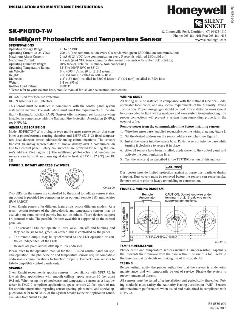

2007 Honeywell International Inc. Honeywell, IntelliSense and DUAL TEC are registered trademarks of Honeywell International Inc.
All other trademarks are the properties of their respective owners. All rights reserved. Made in China.
Please contact your local authorised Honeywell representative for product warranty information.
Contacter un revendeur Honeywell autorisé pour obtenir des informations sur la garantie de ce produit.
Contatti il suo rappresentante Honeywell per ulteriori informazioni su prodotti e garanzia.
Por favor contacte con su distribuidor Honeywell Security para información sobre la garantía del producto.
Contacte o representante autorizado Honeywell local para obter informações relativas a garantia.
P/N 800-02430 Rev B
ACCESSORIES / ACCESSOIRES / ACCESSOIRES / ACCESSORI /
ACCESORIOS / ACESSÓRIOS
SMB-10
(P/N 0-000-110-01)
Swivel Mount Bracket
Muurbeugel
Rotule de montage
Snodo da parete
Rotula de montaje a pared
Rótula para montagem em parede
SMB-10C
(P/N 0-000-111-01)
Swivel Mount Ceiling Bracket
Plafondbeugel
Rotule de plafond
Snodo da soffitto
Rotula de montaje a techno
Rótula para montagem de tecto
SMB-10T
(P/N 0-000-155-01)
EN 50131-1 &
EN 50131-2-4
NCompliant
Swivel Mount Bracket w/Tamper
Muurbeugel met sabotage schakelaars
Rotule de montage avec autoprotection
Snodo da parete con tamper
Rotula de montaje a pared con tamper
Rótula com Tamper
DT7000-LRLK1
27 m x 5 m
Long Range Lens Kit
Lenzenset groot bereik
Kit lentille longue portée
Kit lenti a lunga portata
Kit de lentes de largo alcance
Kit de Lentes de Longo Alcance
DT7000-HSLK1
11 m x 12 m
High Security Lens Kit
Lenzenset high security
Kit lentille haute sécurité
Kit lente alta sicurezza
Kit de lentes de alta seguridad
Kit de Lentes de Alta Segurança
DT7000-PALK2
11 m x 12 m
Pet Alley Lens Kit
Lenzenset huisdieren
Kit lentille immunité aux petits animaux
Kit lente animali domestici liberi
Kit de lentes inmunes a las mascotas
(Pet Alley)
Kit de Lentes Imunidade a Animais
EN 50131-1 & EN 50131-2-4
Compliant when mounted at:
Geschikt indien gemonteerd op:
Conforme si le montage est effectué à une hauteur de:
Conforme quando montato a:
Se adecua cuando está montado en:
Em conformidade quando montado a:
11.8 – 2.7m
21.2m
Other Honeywell Accessories manuals

Honeywell VERSAFLOW MAG 1000 User manual

Honeywell

Honeywell VERSAFLOW MAG 1000 User manual

Honeywell UV100RM TrueUV Operation manual

Honeywell

Honeywell UV100RM TrueUV Operation manual

Honeywell DC515SP2 User manual

Honeywell

Honeywell DC515SP2 User manual

Honeywell SHK8M User manual

Honeywell

Honeywell SHK8M User manual

Honeywell TE923WD - Display Unit For Professional Weather Station... User manual

Honeywell

Honeywell TE923WD - Display Unit For Professional Weather Station... User manual

Honeywell RPW300 User guide

Honeywell

Honeywell RPW300 User guide

Honeywell DC515 P2 Series User manual

Honeywell

Honeywell DC515 P2 Series User manual

Honeywell SC1000 User manual

Honeywell

Honeywell SC1000 User manual

Honeywell C7046C User manual

Honeywell

Honeywell C7046C User manual

Honeywell RPW111A User guide

Honeywell

Honeywell RPW111A User guide

Honeywell 203255AA User manual

Honeywell

Honeywell 203255AA User manual

Honeywell HMR3100 User manual

Honeywell

Honeywell HMR3100 User manual

Honeywell Lyric RF6GB User manual

Honeywell

Honeywell Lyric RF6GB User manual

Honeywell FP5000 2AR Series User manual

Honeywell

Honeywell FP5000 2AR Series User manual

Honeywell RPW319 Manual

Honeywell

Honeywell RPW319 Manual

Honeywell DW915 Series Operating instructions

Honeywell

Honeywell DW915 Series Operating instructions

Honeywell RPWL100A User manual

Honeywell

Honeywell RPWL100A User manual

Honeywell Dual Tec DT-500 User manual

Honeywell

Honeywell Dual Tec DT-500 User manual

Honeywell RPW112A User guide

Honeywell

Honeywell RPW112A User guide

Honeywell C7735A1000 User manual

Honeywell

Honeywell C7735A1000 User manual

Honeywell RPW318 Manual

Honeywell

Honeywell RPW318 Manual

Honeywell VFD CORE User manual

Honeywell

Honeywell VFD CORE User manual

Honeywell H7012A User manual

Honeywell

Honeywell H7012A User manual

Honeywell PRO 2000 Series Operation manual

Honeywell

Honeywell PRO 2000 Series Operation manual

Popular Accessories manuals by other brands

Omron E3X-NA - datasheet

Omron

Omron E3X-NA - datasheet

Kogan SMARTERHOME R400A user guide

Kogan

Kogan SMARTERHOME R400A user guide

Lumina KEB 1920F manual

Lumina

Lumina KEB 1920F manual

Anritsu IQ Fiber Master MT2780A user guide

Anritsu

Anritsu IQ Fiber Master MT2780A user guide

Bowflex SelectTech 5.1 Bench Assembly & owners manual

Bowflex

Bowflex SelectTech 5.1 Bench Assembly & owners manual

HONGYUV HY-WDS2E operating manual

HONGYUV

HONGYUV HY-WDS2E operating manual

Porter 4414061 ASSEMBLY, MAINTENANCE & USAGE MANUAL

Porter

Porter 4414061 ASSEMBLY, MAINTENANCE & USAGE MANUAL

APG FLR Series Operator's manual

APG

APG FLR Series Operator's manual

Gogen ME SENZOR 32 user manual

Gogen

Gogen ME SENZOR 32 user manual

PCB Load & Torque M1631-06C Installation and operating manual

PCB

PCB Load & Torque M1631-06C Installation and operating manual

EVAPCO ATC-E Rigging and Assembly Instructions

EVAPCO

EVAPCO ATC-E Rigging and Assembly Instructions

ROSE DISPLAYS ANOFRAME ROUND ASSEMBLED-SLATWALL manual

ROSE DISPLAYS

ROSE DISPLAYS ANOFRAME ROUND ASSEMBLED-SLATWALL manual

Waterpik Water Flosser CC-01 Series quick start guide

Waterpik

Waterpik Water Flosser CC-01 Series quick start guide

Huawei eNodeB user guide

Huawei

Huawei eNodeB user guide

Goobay 53934 user manual

Goobay

Goobay 53934 user manual

Waterpik Waterflosser WP-900 manual

Waterpik

Waterpik Waterflosser WP-900 manual

VWR International 2310 Installation and operation manual

VWR International

VWR International 2310 Installation and operation manual

Makita CB100D instruction manual

Makita

Makita CB100D instruction manual

manuals.online logo
manuals.online logoBrands
  • About & Mission
  • Contact us
  • Privacy Policy
  • Terms and Conditions

Copyright 2025 Manuals.Online. All Rights Reserved.