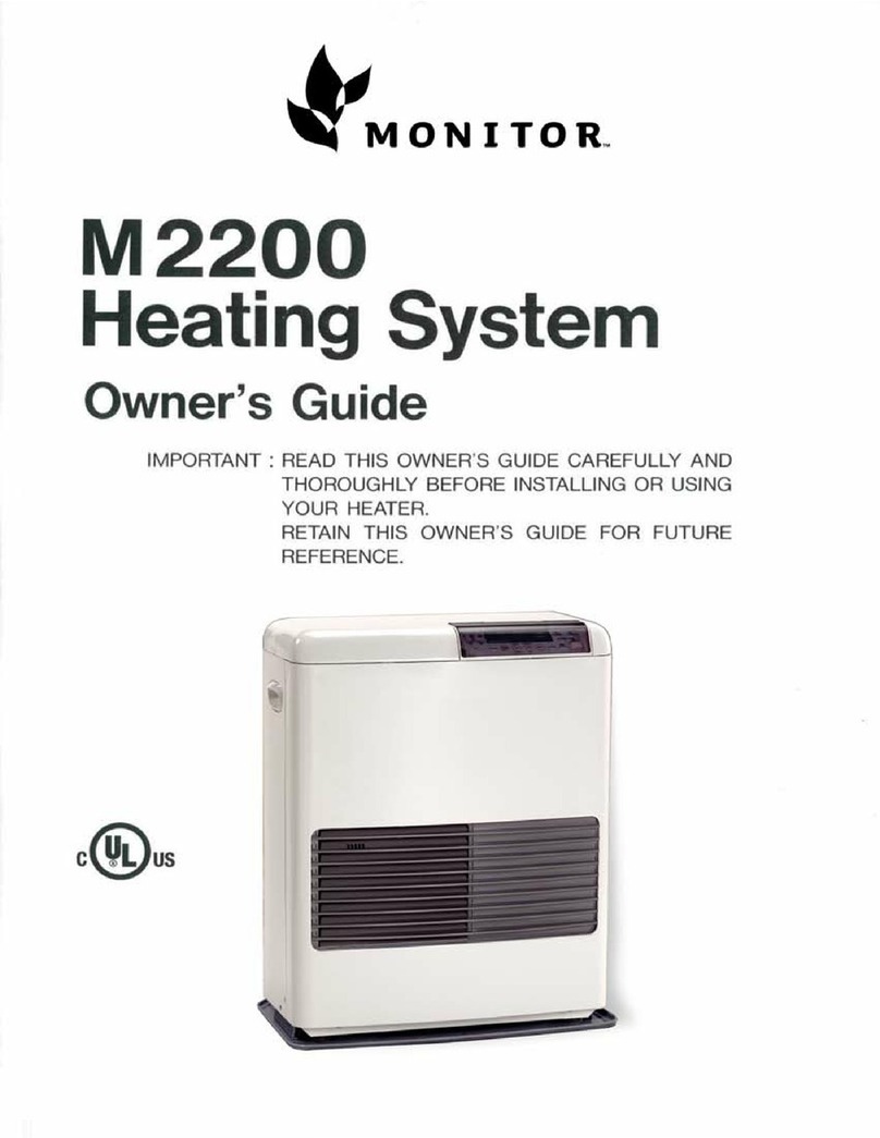
Monitor M2400 User manual


SAFETY
ALERT
SYMBOL
These
symbols
appear
as
important
safety
precautions
and
should
be
understood
and
followed
bythe
owner
to
assure
safe
operation
ofthe
heater.
For
Quick
Reference
Page
SECTION
A:
^Important
Caution
1
SECTION
B:
Specifications
5
SpecialFeatures
5
Safety
Features
5
SECTION
C:
ToolsNeeded
for
Heater
Installation
6
Accessories
YouMay
Need
7
Flue
PipeExtensions
7
SECTION
D:
HeaterInstallation
9
Flue
Pipe
Clearances
10
SECTION
E:
Fueling
15
FuelingOptionsAvailable
15
External
Tank
Installation
15
EmptyFuelTank
16
SECTION
F:
StartingInstructions
17
SECTION
G:
AdjustingRoomTemperature
18
SECTION
H:
Turning
Offthe
Heater
18
SECTION
I :
Relighting
the
Heater
18
SECTION
J:
Programming
the
Heater
19
Setting
the
Clock
19
Programming
for
AutomaticHeaterOperation
20
Manual
Operation
20
SECTION
K:
ProtectiveFeatures
21
Loss
of
Power-AutomaticReset,
Child
Lock
21
ElectricalFuse
21
OverheatPrevention
21
SECTION
L:
Care
ofthe
Heater
22
SECTION
M:
TroubleshootingGuide
24
2001COPYRIGHT
©
MONITOR
PRODUCTS,
INC.,

SECTION
A
IMPORTANT
CAUTION
AWARIMING
USE
ONLYCRYSTALCLEARKEROSENE.NEVER
USE
GASOLINE,WHITEGAS,CAMPFUEL
OR
OTHER
FLAMMABLELIQUIDS.
USEOF
SUCH
FUELS
CAN
RESULT
INAN
EXPLOSIVEFIRE
AND
CAUSESEVEREINJURY.
KEROSENE
ONLY
GAS
2\CAUTION
1.
Makesurethatthere
isno
fuelleakage
from
fueltank
and
fuelpipejoint.
2.
Makesurethatfluepipe(exhaustpipe,
air
supplyhose)
is
connected
properly.

3.
Keepheater
clean
anddonot
store
any
flammableitems
onor
near
the
heater.
4.
Don't
usethe
heater
for
dryingclothes.
5.
Shouldanythingabnormaloccur
inthe
heater,remaincalm,Turn
ItOff(Do
Not
Unplug)
and
contactyourMonitordealer.
6.
Risk
of
burns.
Flue
pipe
and
louver
may
havehighsurface
temperature.

7.
Donot
place
yourself
or
others
too
close
tothe
heater.
8.
Installation
of
heater
in
extremehumidity
or
dustareas
isnot
recommended.
Any
removal
of
unitparts
or
remodeling
is
strictlyforbidden.
9.
Donotsitonthe
heater.
Placingornaments
or
plants
onthe
heater
isnot
recommended.
Excess
heat
may
causedamage
to
ornament
or
plant
and
overwatering
or
spilling
of
water
may
causeshock
toyouor
damage
tothe
heater.
10.
In
areas
of
heavysnow
accumulation,
flue
pipe
may
need
tobe
installed
higher
to
avoidbeingburied.
In
openareaswithstrongwind,
a
windbreak
maybe
necessary
to
avoidexhaustgasesbeingblown
back
into
the
intake
and
causingpoor
combustion.
Long
Extension
kit
-»-
24"min
-
(60cm)

11.
Donot
install
nor
exhaust
the
flue
pipe
into
a
crawlspace
or
underneath
floor.nor
into
a
flue
or
chimney.
X
]
'
\
/
>•
7
/
X
•---Flue
or
Chimney
12.OPERATING
ALTITUDESHIGHERLIMITS
Thisheater
is
designed
tobe
usednormally
upto
3000
feet
above
sea
level.
Touse
over3000feet,
butnot
higher
than
7000
feet,
consultwithyourdealer
on
correct
air
damperuse.
13.OPERATING
TEMPERATURE
LIMITS
Please
usethe
Monitorwithin
the
range
of
temperaturesindicated
bythe
shadedareashown
onthe
graph
below.
OperatingTemperatureLimits
Point
A
InsideAreaTemperature
— 4°F
OutsideTemperature
—
22°F
Point
B
InsideAreaTemperature60°F
OutsideTemperature
-40°F
-100 2040
InsideAreaTemperature
(°F)

SECTION
B
SPECIFICATIONS
Model
Monitor
2400
Fuel
Type
Crystal
ClearKerosene
Heater
Efficiency
93%'
HeatRatingHigh
:
43,000
BTU/hour
H.Medium
:
32,000BTU/hour
L.Medium
:
24,600BTU/hour
Low:
16,200
BTU/hour
Heater
OutputHigh
:
37,200BTU/hour
H.Medium
:
26,900BTU/hour
L.Medium
:
20,700
BTU/hour
Low
:
13,600
BTU/hour
Fuel
Tank
Fuel
Consumption
Separate
(Notsuppliedwithheater)
High
:
0.319
Gallon/hour
H.Medium
:
0.24Gallon/hour
L.Medium
:
0.18Gallon/hour
Low
:
0.12Gallon/hour
Power
Source
120
Volts
AC;
60
Hz.
Power
ConsumptionIgnition
:310
Watts
Operation
:68
Watts(Average)
Heated
Air
Delivery
High:
388
Cubicfeet/minute
H.Medium:
388
Cubicfeet/minute
L.Medium:
330
Cubic
feet/minute
Low:
300
Cubicfeet/minute
Vent
PipeHole
2/1>-inches
Diameter
Dimensions
Height:
26.6
inches
Width:
28.7inches
Depth:
14.0inches
Weight
82
Pounds,empty
*Net
Efficiency
is
88%,
A.F.U.E.is
84%
SPECIAL
FEATURES
AUTOMATIC
IGNITION
MEMORY
BACK
UP:
Set
memory
canbe
kept
in
case
of
power
failure
forupto30
minutes.
DUAL
BLOWERS:
Separatefans
for
combustion
and
room
air
circulation.
THERMOSTATICALLY
CONTROLLED:Adjusts
tothe
desired
roomtemperature.
BUILT-IN
TIMER:Heater
willautomaticallyoperate
as
programmed
bythe
user.
AUTOMATIC
RESET
AFTER
POWER
FAILURE:
Heater
willautomaticallyresumeoperationafterpower
is
restored.
INDICATOR
LIGHTS
:
Easy-to-seesignalsshowwhen
heater
isin
operation,whentimer
is
activated,
and
when
the
burner
is
operating.
CHOICE
OF
FUEL
SUPPLY:Connect
to
separate
tank.
MULTIPLE
HEAT
EXCHANGER:Extracts
88%of
heat
from
burner.
CLEAN
OPERATION:
Products
of
combustion
are
vented
outside.
CONSUMES
NO
ROOM
AIR
:Airforcombustion
is
drawn
from
outside.
EASY
INSTALLATION:
Includes
all
partsrequired
for
standard
installation.
SAFETY
FEATURES
SAFE
RE-LIGHTING:Heater
will
not
restart
until
its
combustionchamber
has
cooled.
ELECTRICAL
PROTECTION:
Heater
automatically
shuts
off
inthe
unlikely
event
ofa
malfunction
inthe
electrical
circuitry
or
disruption
ofthe
powersupply.
NO
EXHAUST
IN
ROOM:
Products
of
combustion
are
dischargedoutdoors.
FLUE
PIPE:Outside
airis
drawnthrough
a
pipe-within-
a-pipe
ventingsystem.Thisprocesspreheats
combustion
airand
regainsheatfromexhaust
gases.
A
CAUTION-ALTERNATE
POWER
SOURCES
The
Monitor
2400
may not
operate
when
powered
by
sources
such
as an
auxiliary
generator,
UPS
(Uninterrupted
Power
Source),
inverters,
etc.
Check
with
your
dealer
for
guidance
on
specific
applications.

SECTION
C
Before
installing
your
heater,
be
sure
to
check
and
comply
with
local
and
statebuilding
and
electricalcodes
that
may
apply
to
ventedheaters
in
your
area.Permanentwiringmust
be
installed
bya
licensedelectrician.
TOOLS
NEEDED
FOR
HEATER
INSTALLATION
Check
the
followingcharts
tobe
sure
you
have
allthe
toolsrequired
to
installyourMonitor2400HeatingSystem.
STANDARD
TOOLSAPPLICATION
PhillipsHeadScrewdriver
Installation
of
HeaterParts
Steel
TapeMeasureTakingMeasurements
Penor
PencilMarkingDrilling
Location
Exterior
CaulkCaulkingBetween
Packing
and
Wall
Yardstick
or
LongStraightEdgeCheckingAngle
of
Hole
for
FluePipe
Soapy
WaterLubricatingSleeveHardware
SPECIAL
TOOLS
APPLICATION
ElectricDrillAccommodatingHole
Sawand
Drill
Bit
2>2
inchHole
Saw
AttachmentCuttingHole
for
FluePipe
Long
Y±
inchDrill
Bit
DrillingPilotHoleThroughWall
Level
CheckingAngle
of
Hole
for
FluePipe
andfor
checking
heater
level.
Fig.
1

ACCESSORIES
YOUMAY
NEED
Check
the
listbelow
andsee
your
MPI
dealer
for
accessories
youmay
need
or
want
for
installation
of
your
heating-
system.
/K
CAUTION:
Only
usethe
flue
pipe
supplied
with
the
Monitor2400,
orthe
approved
accessory
kits
available
from
your
Monitor
or
dealer.
ACCESSORY
MediumAdjustableFluePipe
Kit
LongAdjustableFluePipe
Kit
LifterPump
Extra
Short,Short,Medium
or
P/N
8051
P/N
8052
P/N
1101
APPLICATION
For
use
wherewallthickness
isupto12
/4
inches
For
use
wherewallthickness
isupto20
inches
For
use
withlargecapacity
tank
wheregravityfeed
isnot
practical
For
use
where"standard"
installation
isnot
practical
LongExtension
Kitor
ElbowAdapter
Kit
(See
FluePipeExtensions,page
7)
Fitting
and
Tank
For
large
capacity
fueling:
Tobe
dealer
installed
EXTENSION
KIT
LENGTH
Extra
ShortExtension
Kit
Short
Extension
Kit
Medium
Extension
Kit
Long
Extension
Kit
P/N
82
12
P/N
8004
P/N
8003
P/N
8002
7!/6
to
1
1
1/2
inches(18.2
to
29.2cm)
11
1/2to
20'/4
inches(29.2
to
51
.4cm)
20!/4
to38
inches
(51
.4
to
96.5cm)
38
to73
inches(96.5
to
185.4cm)
FLUE
PIPEEXTENSIONS
Four
standardextension
kits
are
available
fromyour
Monitordealer.Most
installations
canbe
madewith
one
of
these
kits.
In
special
cases,custom
installations
may
be
required.These
maybe
made
with
components
purchasedfromyourdealer.
In
any
installation
the
followinglimitationsMUST
NOT
BE
EXCEEDED.
1.
The
totallength
ofthe
intake
or
exhaustpipeshould
not
exceed
10
feet(3m)with
3
elbows,
13
feet
(4m)
with
2
elbows,
or161/2
feet
(5m)with
1
elbow.
2.
Theseelbowsshouldinclude
theone
used
atthe
heater
butnottheoneontheair
supplyhose
northe
integralbends
inthe
fluepipe.(SeeFigure
2)
3.The
correctdamper
as
shown
on
Page
13
must
be
used.

Exhaust
Elbow
Air
SupplyHose
90°
Joint
Flue
Pipe
Fig.
2
~k
Donot
count
8

SECTION
D
HEATER
INSTALLATION
Step
1:
Fill
Out
Owner
Registration
Card
Remove
yourowner
registration
cardfrom
the
plastic
envelope
containing
the
owner'sguide.
It
should
be
filled
outand
mailed
as
soon
as
possible.
Step
2:
Check
for
Parts
Before
discardingpackingmaterials,
be
sure
you
have
located
the
following:
FluePipe
Sleeve
Nut
Spill
Tray
Room
Temp.Sensor(attached
tothe
rear
ofthe
heater)
Cardboard
Template
"STANDARD"
Damper
"EXTENSION"
Damper
Wall
Clamp
Rubber
Packing
Joint
Pipe
Cloth
Insulation
Cover
Outer
Flange
PipeHolder
Small
Bagof
Screws
Tapping,
Type
A —
Tapping,
Type
A —
For
securing
sleeve
and
wall
clamps
For
securing
wallclamps
SIZE
Tapping
Tapping
Fig.
3
Step
3:
Choose
a
Location
for
Your
Heater
In
choosing
a
location
for
your
heater,
the
following
guidelinesmust
be
considered:
•
The
heater
MAY
be
installed
on
combustible
floors.
•
The
areaaround
the
heatershould
befreeof
obstaclesthatmightinterferewith
thefree
flow
of
air.
Allow
the
clearancesshown
in
Figure
4.
12"
(30cm)
51/2"
(13.5cm)
(15cm)
Fig.
4
39"
(100cm)
If
the
unit
is
installed
so
that
itis
enclosed
on
bothsides
and
top,
the
following
instructions
shall
be
carried
out.
With
the
side
andtop
clearances
as
shown
inthe
illustration
(Fig.Sa)
the
front
ofthe
Monitor
shall
be
placed
so
that
the
front
surface
protrudes
5
inches
(12.5
cm)
beyond
the
enclosure.
(SeeFig.
5b)
5"min
(12.5cm)
(13.5cm)
6"min
(15cm)6"min
(15cm)
Fig.
5a
Fig.
5b
ZJA
CAUTION:
•
The
heatermust
notbe
installed
ina
fireplace.
•
An
AC
walloutletmust
be
withinreach
ofthe
heater'spowercord.Extensioncordsmust
notbe
used.
•
The
areaoutsidewhere
the
fluepipe
will
emerge
should
be
free
of
foliage,fuelstoragetanks
and
flammableobjects.
Air
shouldcirculatefreely
in
the
area.Allow
the
clearances
shown
in
Figure
6on
the
nextpage.
•
The
wallwherefluepipeholewill
becut
should
be
free
of
plumbingpipes,electricalwires,studs,
air
ducts
and
otherobstacles.
NOTE:
Use the
cardboard
template
provided
with
your
heater
for
flue
pipe
location.
9

FLUEPIPECLEARANCES
Flue
pipeinstallationsshouldprovide
for
venting
toan
unconfined
spacethroughwhichthere
isa
free
flow
of
outdoor
air.Clearances
to
adjacentwalls
or
obstaclesmustcomplywith
the
requirementsshownbelow.
FrontalClearanceCombustible
"""
"'"
'
uiiumu
ACAUTION:
1;
Do
not
attachanythingonto
the
outlet
or
of
the
fluepipe.
t
>•
(30cm)
more
5K"_4—
(13.5cm)
Body
-
Clamp
-fe^
\
Heater
•*
4
-Wall
Any
construction
3"
aboveFluePipe
(7.5
must
not
come
_>
cm)
within
24"
(60cm)
or
of
front
obstacle
more
«->(«
24"
(60cm)
*
or
more
K
Flue
Pipe
r
8"
(20cm)
or
more
I
Ground
or
slabsurface
I
1
FrontObstacle
Overhead
Clearance
fVvmhi
ictihlo
IIIIIIIIIIIIIIIIIIIIIIMIIIIIIIN
12"(:
or
m
Body
Clam
Heate
I
30cn
ore
5,
(1-
P
r
_
i)
£••_
3.5cr
j&
^_
n)
\
Non-combustible
"
Wa"
Combustible
nun
mil
iniiiimtii
iHiU!iii[|[]j||iiiiimiimiuH]i||ii|
)
Jr
24"
(60cm)
•Jr
or
more
IIIIIIIIIIIIIHIIHIllr
45'
/
T
~~^/
12"
(30cm)
/
or
more
UjC
*
~
FluePipe
Ground
or
slabsurface
SideClearance
Heater-
Body
Clami
\
]
D
\
•H!
Sideobstacle
iiiiiiimiiiimmiiiiMiiiiimiiM|iiii|iinii
T
18"
(45cm)
or
more
fr*n~
FluePipe
Wall
IMPORTANT:
(1)
In
areas
of
heavy
snow
falls,
ground
surface
clearance
must
be
increased
according
to
average
snow
falls,
to
prevent
flue
pipe
from
being
buried.
Long
Extension
kit
(2)
In
open
area
with
strong
wind,
a
wind
break
may be
necessary.
i»-
24"min
-^
(60cm)
Fig.
6
10

Step
4:
Drill
a
PilotHole
NOTE:
The
following directions apply
to
"standard"
installation.
For
other methods, follow instructions
included with accessory kits.
Use
the
template
to
position
the
hole
tobe
drilled.
The
"green
dot"indicates
the
exactcenter
ofthe
hole.Using
an
electric
drill
and
along
drill
bit,
make
a
pilot
hole
through
the
wall(Figure
7).Be
sure
the
holeextendsthrough
the
outsidewall.
Position
of
hole
Template
Fig.
7
/!\
CAUTION:
The
opening
onthe
inside wall should
be
approximately
1/4
inch higher than
on the
outside wall
so the
flue pipe
will
slope downward when installed.
This
will
allow condensation
to
drain outdoors.
Step
5:
Cutthe
Hole
forthe
Flue
pipe
Using
a
hole
saw
attachment
andan
electric
drill,
cut
a
21A
inch
diameter
hole
through
the
inner
and
outer
walls
(Figure
8).
After
the
hole
is
cut,
usea
straight
edge
anda
level
tobe
sure
the
inside
opening
is
approximately
%
inch
higher
than
the
outside
opening.
NOTE-.After
cutting
the
inside wall,remove
the
insulation.
Make
sure there
are no
obstructions inside
the
wall,
such
as
electrical wiring, water pipes,
hot
air
ducts, etc.
(6mm)
Fig.
8
Step
6:The
Flue
Pipe
istwo
Sectins,
Flue
Pipe
A
and
Flue
Pipe
B
Install
the
Flue
Pipe
A
From
INSIDE
the
building,
insert
the
fluepipe
A
(with
arrow
pointing
"up")
into
the
hole.
Fasten
the
flue
pipe
with
the
3#8X
3/4
tapping
screws
(FigureQ
and
10).
(See
Figure
for
screw
size
and
application.)
NOTE:
Top
center port
is an
extra exhaust port.
#8x%
tapping
screw
Fig.
9
Room
Flue
Pipe
A
1/4"
(6mm)
11

Step
7:lnstallFluePipe
B
Wall
Thickness:
5-8
'/>
inches
1.
Slide
the
outerflange
andthe
rubberpackingonto
Flue
pipe
B.
(Figure
11)
Rubber
Packing
Outer
Flange
.
A
'/'A
Rubber
Packing
Outer
Flan9e
Fig.
11
FluePipe
B
2.
Spreadcaulkingmaterial
onthe
inside
ofthe
rubber
packing
if
required.(Figure
12)
Rubber
Packing
Fig.
12
3.Itis
imprtant
to
keep
the
"UP"mark
onthe
rubber
packing
atthetop
whilescrewing
in
Fluepipe
B.
Hold
the
packing
in
placewhilescrewing
in
Flue
pipe
B
until
itisthe
tight.(Figure
13)
Rubber
Packing
Fig.
13
Flue
Pipe
B
Wall
Thickness:
v«
-5
inches
1.
Setthe
Sleeve
Nutt the
FluePipe
B and
turn
the
Sleeve
Nut
counterclockwise.Side
the
OuterFlange
andthe
Rubber
Packing
onto
the
FluePipe
B.
(Figure
14)
Rubber
Packing
\Rubber
Packing
^
'•
-n
J^
((((
i
ytr
V
r-
Sleeve
Nut
OuterFlangeFig.
14
;
I
L
IF
Sk
o
/
1
ut
/
F
;eve
er
Flange
"lue
Pipe
B
Nut
2.
Spread
caulking
material
onthe
inside
ofthe
Rubber
Packing
if
required.(Figure
12)
3.Itis
imprtant
to
keep
the
"UP"mark
onthe
Rubber
Packing
atthetop
whilescrewing
inthe
Flue
Pipe
B.
Hold
the
Rubberpacking
in
placewhilescrewing
in
the
FluePipe
B
until
itisthe
tight.(Figure
13)
4.
Turn
the
Sleeve
Nut
clockwise
and
tighten.
(Figure
15)
RubberPacking
Flue
Pipe
A /
Outer
F|ange
Sleeve
Nut
FluePipe
B
Fig.
15
12

Step
8:
Install
the
SpillTray
Place
the
spilltray
onthe
floorwhere
you
plan
to
locate
your
heater.
Remove
the2
sets
of
screws
from
the
cabinet(Figure
16).
Position
the
heater
onthe
spilltray
sothe
legs
ofthe
cabinet
fit
into
the
circular
indentations
inthe
spill
tray
(Figure16).
Retainers
Fig.
16
Legs
Spill
Tray
Step
9:
Level
the
cabinet
In
order
for
heater
to
operateproperly.
It
must
be
positioned
ona
levelsurface.Ensureproperleveling
by
adjustingeach
legandby
using
a
carpenterslevel
to
checkbothside
to
side,
and
front
to
backlevel
condition.
Attach
and
tightenbothsets
of
retainers
and
screws.
Step
10:
Install
the
JointPipe
At
the
rear
ofthe
heater,slide
the
large
end
opening
of
the
joint
pipe
into
the
exhaustport
outlet
ofthe
heater.
Be
sure
the
joint
pipe
is
fullyseated.Slide
the
fabric
coverover
the
joint
pipe
(Figure
17)
The
o-rings
thatseal
the
joint
pipe
maybedryand
tight.
A
little
soapywater
will
ease
installation.
Fabric
Cover
Joint
Pipe
Fig.
17
Step
11:
Connect
the
Heater
tothe
FluePipe
Move
the
heatertoward
the
wall,guiding
the
jointpipe
into
the
center
port
ofthe
flue
pipe
(Figure
18).
Be
sure
the
jointpipe
is
completelyinsertedinto
the
flue
pipe.
Step
12:
Install
theAir
Damper
If
installation
is
standard(that
isno
extensionkits
are
required),
place
theair
dampermarkedwith
a
"STANDARD"
over
theair
intakeflange
onthe
flue
pipe
(Figure
19).
Place
the
hosebandaround
theendoftheair
supply
hose.
Push
theair
supply
hose
onto
theair
intake
flange
and
secure
the
hosewith
the
hoseband.
NOTE:Do
not
place
intake
hose
onto
metal
capped
exhaust
port.
13

NOTE:
The
"STANDARD"
damper
is to be
used
with
extension
kits
up to a
total
overall
length
of 73
inches
and a 1
bend
(90°
elbow)
The
"EXTENSION"
damper
must
be
used
when
extension
kit or
kits
exceed
20
inches
and 2 or 3
bends
are
used.
Step
15:
Recheck
the
Heater
Beforeproceeding,checkagain
tobe
surethere
are
no
flammablematerialsclose
tothe
heater.
Check
to
be
sure
the
heater
is
level.
Examine
the
fluepipe
tobe
sureconnections
are
tight.
Step
13:
Install
the
Flue
Pipe
Holder
Place
the
ring
ofthe
fluepipeholderaround
the
flue
pipe.
The
otherside
ofthe
holderhooks
ina
slot
directly
above
the
jointpipe
atthe
rear
ofthe
heater
(see
Figure20).
FluePipeHolder
Fig.
20
Step
14:
Secure
the
Heater
Insert
the
narrowends
ofthe
wallclampintosockets
on
the
rear
ofthe
heater.
Loosen
the
adjustment
screws
and
extend
the
clamp
untiltheytouch
the
wall.Fasten
the
clamp
tothe
wallwith
2
#8x%
tappingscrew.
NOTE:
If use of
wall
clamps
is not
feasible
or
practical,
the
heater
should
be
secured
by
screws
to
floor
through
punched
holes
in
spill
tray.
14

SECTION
E
FUELING
/!\
WARNING:
Use
onlycrystalclearkerosene(Reddyed
or
clearkerosene
orlow
sulphur
#1
oil).Neber
use
gasoline,whitegas,campfuel
or
otherflammableliquids.
Useof
suchFuels
can
result
inan
explosive
fire
and
causesevereinjury.
FUELINGOPTIONSAVAILABLE
Fueling
of
yourMonitor2400HeatingSystem
canbe
accomplished
inoneof2
ways:
1.
Gravity
Fed
LargeCapacityExternalTank:
Practical
for
largeheatingneedswherebulkdelivery
of
kerosene
is
available.Thissystemshould
be
installed
bya
qualifiedplumber
or
fuelsupply
technician.
2.
Large
Capacity
ExternalTank
with
Pump:
For
largeheatingneedswhere
a
gravity
fed
system
is
not
practical.
An
electriclifterpump,especially
designed
foruse
with
your
Monitor
2400
heating
system,
is
available
from
yourdealer.
When
using
a
gravity
fed
tank
or
pumpingsystem
to
supply
fuel,
the
inlet
pressure
tothe
heatermust
not
exceed
2.5
psi.
NOTE:lt
is
recmmended
to
install
the
fuel
line
on the
left
side
of the
unit,
with
an
appropriate
shut-off
valve,
and
then
across,
behind
the
unit,
to the
attachment
point
on the
right
rear
of the
heater.
EXTERNAL
TANK
INSTALLATION-
Gravity
Fed
NOTE:External
tank
installations
must
comply
with
the
National
Fire
Prtection
Association
code
NFPA
31
or
locally applicable codes, such
as the
Uniform
Mechanical
Code,
that
are
cnsistent
with
NFPA
31.
Check
with
your
local
building
official.
To
install
a
largecapacity,gravity
fed
externaltank,
follow
the
instructionsbelow,
and
refer
to
Figure
21for
one
possible
installation.
Useofa
qualifiedinstaller
is
recommended.
•
Installation
height
ofthe
bottom
ofthe
fuel
tank
should
be16
inches
or
moreabove
the
floorsurface
on
which
the
heaterstands.Thisensuresthat
inlet
fuelpressure
will
be
sufficient.
•Thetopofthe
fuel
tank
should
beno
higherthan
8>2
feetabove
the
floorunder
the
heater.Heights
above
8/4
feetwillexceed
the2.5psi
inletlimit,
and
a
pressurereducerwillneed
tobe
installed
at
or
near
the
unit.
•
The
horizontallength
of
pipingshould
not
exceed
100
feet
and
should
be
free
of
sharpbends
or
obstructions.
•
Pipingshould
include
no
inverse
U-type
bends
(to
avoid
air
locks,
which
could
block
the
fuelsupply).
•
Only
%
inch
OD
copper
tubing
should
be
used.
The
tubing
should
be
bentcarefully
to
avoidcrimping.
•A
fuel
filter
is
recommended
foruseonthe
fuelline
near
the
tank,
anda
shut-offvalveshould
be
installed
atthe
tank.
•A
flareadaptor
canbe
used
to
make
a
flaredtubing
connectionbetween
the
unit
andthe
filter
atthe
tank.
•The
fueltankshould
be
located
no
closerthan
3
feet
toa
source
of
heat.
•
The
fuel
tank
shouldhave
an
opening
for
filling
on
thetopand
vent
with
a
weather-proof
caponthe
side.
On
sometanks
the
vent
and
fill
spout
usethe
sameopening.
Whenusing
a
gravity
fed
tank
to
supplyfuel,
the
inlet
pressure
tothe
heatermust
not
exceed
2.5
psi.
The
Monitor2400comesequippedwith
a
3/a"
pipe
thread
connection.
A
straight,
or90
degree
pipe-to-
flare
fitting
ora
firomatic
valve
canbe
used
forthe
fuellineconnection.
Ifa
firomaticvalve
is
being
used:
Valve
Position-Open/Close
Turncounterclockwise
to
open,clockwise
to
close.
If
threaded
valvestem
is
sticking
up
about
YA",
valve
is
open.
If
handlescrews
off
stem,valve
is
closed.
15

Outdoor
Fuel
Tank
Shut-off
Valve
Flare
Connection
tion
maximum
H'
Threaded
Connection
(a4m)
1
-J
%"
OD
Copper
Tubing
NOTE:
Fuel
tank
must
be a
minimum
3
feet away
from
flue pipe.
NOTE2:A
fusible link
valve
should
be
installed
in
the
fuel line behind
the
heater.
Check
local codes
and
regulations. Fig.
21
CAUTION:
Ensure that there
is no
fuel leakage
from
any of the
fuel line fittings
and
connections.
EMPTY
FUEL
TANK
If
atany
timeduring
the
operation
of
your
heater
you
find.
•
Displaywindowshows
"E14".
•
No
heat.
•
No
flame.
You
can
assume
youareoutof
fuel.
Shouldthis
situation
occur,
take
the
followingsteps.
Step
1:
Turn
the
Heater
Off
Press
the
Operation
Button
toputitinthe
"Off"
position.
Step
2:
Refuel
Refillyour
fuel
tank
with
kerosene.
Step
3:
Turn
the
Heater
On
Press
the
Operation
Button
toputitinthe
"On"
position.
16

SECTION
F
STARTING
INSTRUCTIONS
Step
1:
Plug
inthe
Heater
Plug
intheAC
cord,
and
route
it
away
from
the
area
of
the
flue
pipe.
Itis
recommendedthat
no
other
applianceshare
the
sameoutlet.
Step
2:
Prime
the
Heater
If
using
the
heater
forthe
firsttime,
orifthe
heater
has
not
been
in
operation
for
sometime,press
the
fuel
set
lever
atthe
lowerrighthandside
ofthe
cabinet
and
release
it
slowly
2 or3
times(Figure22).
/!\
CAUTION:
Donot
continuepressing
lever
repeat-
edly
as
this
may
causeoverfilling
of
constant
levelvalve
inside.
NOTE:After
a
power
outage,
there
is a
three-minute
waiting
period
before
the
unit
restarts,
provided
the
ON/OFF
switch
is in the
"ON"position.
Step
3:
Set
"ON"
Button
Depress
the
operationbutton
toputitinthe
"ON"
position.
The
"OperationLamp"
lights
indicating
"Set
Room
Temperature"
and
"present
room
temperature".
Burner
statuslampswilllight
and
ignitionwillstart
after
approximatelythreeminutes.
In5 to10
minutes
the
circulation
fan
willstart
to
operate,
and
warm
air
will
be
felt
comingthrough
the
cabinet
grill.
Fuel
Set
Lever
Fig.
22
WEEKLY
TIMERCONTROL
Won
TueWedThu
FriSatSun
o
o o
DAY
SET
CLOCK
SET
TIMER
SET
O
O O
SELECT
TEMP
AM
PM
SET
ROOM
CD
BURN
I
TIMER
SELECTOR
Hold
down
for
3
sec.
/ON
Fig.
23
17

SECTION
G
ADJUSTINGROOMTEMPERATURE
Pressing
either
the
"UP"
or
"DOWN"buttonwillincrease
or
decrease
theset
temperature
by2
degrees
increments.
Once
desiredtemperature
is
displayed,press
set
button
to
lockintomemory.
When
the
desiredroomtemperature
is
reached,
the
heater
willautomaticallyshift
to
"H.Medium",
"L.Medium"
or
"Low"burningmode
to
maintain
the
desired
temperature.
When
roomtemperatureexceeds
the
desired
temperature
by
approx.
4
degrees,
the
heaterwill
automaticallyshutoff.
As
roomtemperaturedrops,
the
heater
willautomaticallyre-start
to
maintain
the
desired
temperature.
INSTRUCTIONS
FOR
ECONOMYPLUSMODE
To
engage
the
economyplusmode,simplypressdown
the
button
labeled
"EconomyPlus",
to
disengagepress
again.
NOTE:Operation
switch must
be
"ON"
and in
manual
mode.
Thisfeatureminimizes
the
"ON"
and
"OFF"
cycling
ofthe
unit
by
allowing
itto
overshoot
theset
temperature
by
8
degreesinstead
ofthe
normal
4
degrees.
The
advantages
of
thisfeature
areto
increase
the
overallefficiency
ofthe
unit
by:
1.
Decreasingelectricalconsumption
by
decreasing
the
frequency
of
ignition
cycles.
2.
Reducingheatlossduring
the
prepurge
and
postpurgecycles.
3.
Reducinginefficientcombustionassociatedwithstart
upand
shutdown.
4.
Prolongingcomponentlife
by
decreasingexpansion
and
contraction
of
internalparts.
NOTE:
This
feature
could
be
compared
to
driving
an
automobile
in
stop
and go
traffic
(regular
mode)
versus
highway
driving
with
cruise
control
engaged
(Economy
Plus
mode).
SECTION
H
SECTION
I
TURNING
OFFTHE
HEATER
To
turn
offthe
heater,press
the
OperationButton
to
put
itinthe
"Off"position(Figure23).
The
operation
light
will
go
out,
andthe
fuelflow
will
stop.
After
turningheater
offthe
fans
will
continue
torun
until
unit
has
cooleddown
tothe
pointwhere
the
fanswillautomaticallystop.
RELIGHTING
THE
HEATER
Automaticcontrolspreventyourheater
from
relighting
after
the
OperationButton
has
been
setto
"Off"
until
heater
has
cooled.
If
the
OperationButton
isputinthe
"On"position
during
the
coolingperiod,
the
heaterwill automatically
relight
attheendofthe
period.
18
Table of contents
Other Monitor Heating System manuals
Popular Heating System manuals by other brands

Nibe
Nibe F205P Installation and maintenance instructions

Helios
Helios AIR1-EVH RH Installation and operating instructions

Keston
Keston HEAT 45 instructions

2VV
2VV MOMC1 Series Quick manual

AEG
AEG WSP 2010 Operating and installation instructions

Viessmann
Viessmann Vitotronic 100 HC1 Operating instructions and user's information manual

Imetec
Imetec E0809 operating instructions

Napoleon
Napoleon Galaxy Series Installation and operation manual

ubbink
ubbink Ubiflux F300 installation instructions

UTEK
UTEK DEH-V Series GUIDE FOR INSTALLATION, USE AND MAINTENANCE

NuAire
NuAire MRXBOX-ECO installation manual

Vehicle Systems
Vehicle Systems Aqua-Hot AHE-100-04S Shop Manual