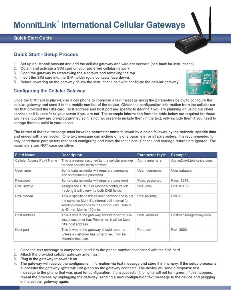
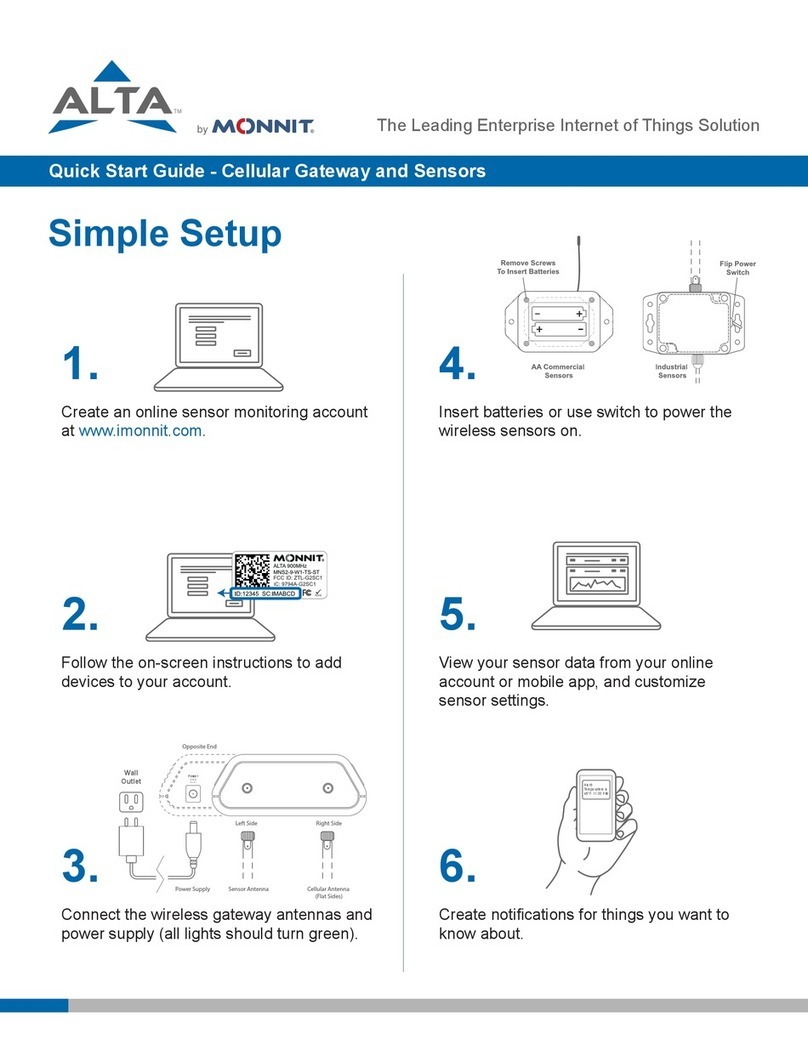
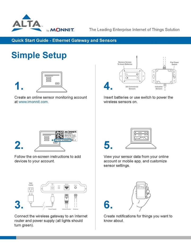
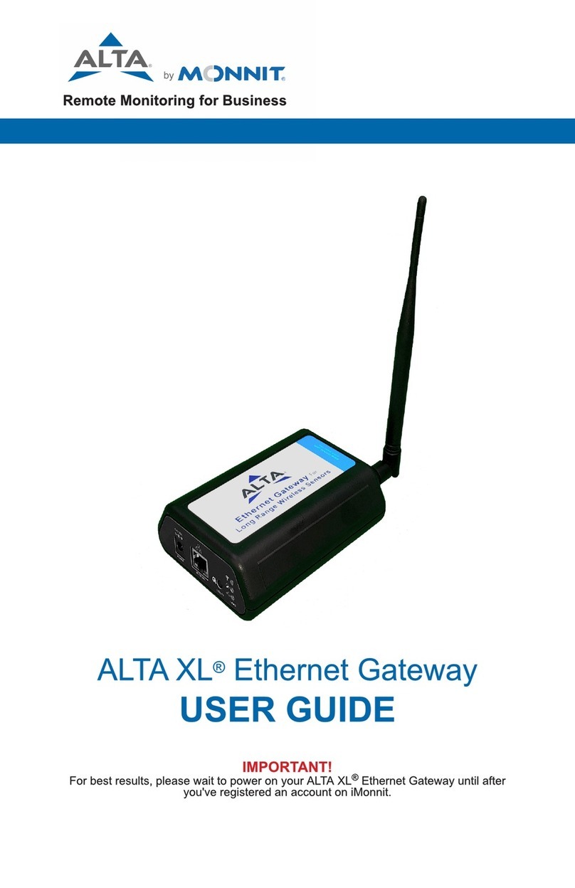
Monnit ALTA EGW4 User manual

Table of Contents
PAGE II
I. ABOUT THE EGW4 GATEWAY 1
ALTA EGW4 GATEWAY FEATURES 1
EXAMPLE APPLICATIONS 1
II. HOW YOUR GATEWAY WORKS 2
III. GATEWAY SECURITY 3
SENSOR COMMUNICATION SECURITY 3
DATA SECURITY ON THE GATEWAY 3
SERVER COMMUNICATION SECURITY 3
IV. GATEWAY REGISTRATION 4
REGISTERING THE EGW4 GATEWAY 4
V. USING THE EGW4 GATEWAY 5
USING THE EGW4 GATEWAY 5
UNDERSTANDING THE EGW4 GATEWAY LIGHTS 5
EGW4 GATEWAY SETTINGS 6
VI. INSTALLING MONNIT EXPRESS SOFTWARE 11
INSTALLING MONNIT EXPRESS SOFTWARE 11
INSTALLING MONNIT MINE SOFTWARE 11
VII. USING THE LOCAL INTERFACE 12
STATUS TAB 12
SETTINGS TAB 13
TROUBLESHOOTING 20
SUPPORT 21
WARRANTY INFORMATION 21
CERTIFICATIONS 23
SAFETY RECOMMENDATIONS 26

I. ABOUT THE EGW4 GATEWAY
Monnit?s ALTA Ethernet Gateway 4 allows your Monnit Wireless Sensors to
communicate with the iMonnit® Online Wireless Sensor Monitoring and
Notification System without the need for a PC. Provide power and plug the
gateway into an open ethernet network port with an internet connection. It will
then automatically connect with our online servers, providing the perfect solution
for commercial locations with an active internet connection.
ALTA Ethernet Gateways are advanced wireless IoT gateways that enable fast
time-to-market solutions. Monnit?s Ethernet Gateway 4 is specifically designed to
respond to the increasing market need for global technology that accommodates
various vertical IoT application segments and remote wireless sensor
management solutions.
ALTA EGW4 GATEWAY FEATURES
- Wireless range of 1,200+ feet through 12+ walls *
- Frequency Hopping Spread Spectrum (FHSS)
- Improved interference immunity
- Encrypt-RF®Security (Diffie-Hellman Key Exchange + AES-128 CBC for sensor data
messages)
- 30,000 sensor message memory **
- Over the air updates (future proof)
- True plug & play, no hassles for internet configuration set-up
- No PC required for operation
- Low-cost cellular service packages
- Local status LEDs with transmission and online status indicators
- AC power supply
* Actual range may vary depending on environment.
** Total messages in memory varies with sensor type (30K total messages for Temperature.
EXAMPLE APPLICATIONS
- Remote Location Monitoring
- Shipping and Transportation
- Agricultural Monitoring
- Vacant Property Management
- Vacation Home Property Management
- Construction Site Monitoring
- Data Center Monitoring
PAGE 1

II. HOW YOUR GATEWAY WORKS
Your ALTA EGW4 Gateway manages communication between your sensors and iMonnit.
When running, the gateway will periodically transmit data on a heartbeat. The gateway will
store information received from sensors until its next heartbeat.
The ALTA EGW4 Gateway is an Ethernet gateway. It uses an Ethernet connection to relay
data received from sensors to iMonnit. Sensors communicate with the gateway; then, the
gateway forwards information to the cloud.
For your wireless sensors to work optimally, orient all antennas for your sensor(s) and
gateway(s) in the same direction (typically vertical). Sensors must also be at least three feet
away from other sensors and the wireless gateway to function correctly. See Figure 1.
More Signal
Less Signal
PAGE 2
Figure 1

III. GATEWAY SECURITY
The ALTA EGW4 Gateway has been designed and built to manage data from sensors
monitoring your environment and equipment securely. Hacking from botnets are in the
headlines; Monnit Corporation has taken extreme measures to ensure your data security is
handled with the utmost care and attention to detail. The same methods utilized by
financial institutions to transmit data are also used in Monnit security infrastructure.
Security features of the gateway include tamper-proof network interfaces, data encryption,
and bank-grade security.
Monnit?s proprietary sensor protocol uses low transmit power and specialized radio
equipment to share application data. Wireless devices listening on open communication
protocols cannot eavesdrop on sensors. Packet level encryption and verification are vital in
ensuring traffic aren?t altered between sensors and gateways. Paired with a best-in-class
range and power consumption protocol, all data is transmitted securely from your devices.
Thereby ensuring a smooth, worry-free experience.
SENSOR COMMUNICATION SECURITY
Monnit sensor to gateway secure wireless tunnel is generated using ECDH-256 (Elliptic
Curve Diffie-Hellman) public key exchange to develop a unique symmetric key between
each pair of devices. Sensors and gateways use this link specific key to process
packet-level data with hardware-accelerated 128-bit AES encryption, which minimizes
power consumption to provide industry best battery life. Thanks to this combination, Monnit
proudly offers robust bank-grade security at every level.
DATA SECURITY ON THE GATEWAY
The ALTA EGW4 Gateway is designed to prevent prying eyes from accessing the data
stored on the sensors. The ALTA EGW4 Gateway does not run on an off the shelf
multi-function OS (operating system). Instead, it runs a purpose specific real-time
embedded state machine that cannot be hacked to run malicious processes. There are also
no active interface listeners that can be used to gain access to the device over the network.
The fortified gateway secures your data from attackers and secures the gateway from
becoming a relay for malicious programs.
SERVER COMMUNICATION SECURITY
Communication between your ALTA EGW4 gateway and iMonnit is secured by packet-level
encryption. Similar to the security between the sensors and gateway, the gateway and
server also establish a unique key using ECDH-256 for encrypting data. The packet-level
data is encrypted end to end, removing additional requirements to configure specialized
cellular VPN?s. The gateway can still operate within a VPN if it is present.
PAGE 3
IV. GATEWAY REGISTRATION
PAGE 4
REGISTERING THE EGW4 GATEWAY
You will need to enter theDevice ID and the Security Code from your EGW4 Gateway in
the corresponding text boxes. Use the camera on your smartphone to scan the QR code
on your gateway. If you do not have a camera on your phone or are accessing the online
portal through a desktop computer, you may manually enter the Device ID and Security
Code. See Figure 2.
- The Device ID is a unique number located on each device label.
- Next, you?ll be asked to enter the Security Code (SC) on your device. A security
code will be all letters, no numbers. It can also be found on the barcode label of
your gateway.
When completed, select the ?Submit?button.
IMPORTANT: Add the gateway and all sensors to the iMonnit portal so that the gateway
can download and whitelist the sensors from the account on boot.
If this is your first time using the iMonnit online portal, you will need to create a new
account. If you have already created an account, start by logging in. For instructions on
how to register for an iMonnit account, please consult the iMonnit User Guide.
Figure 2

V. USING THE EGW4 GATEWAY
USING THE EGW4 GATEWAY
UNDERSTANDING THE EGW4 GATEWAY LIGHTS
PAGE 5
Steady Green: Communication with sensors is ok.
Blinking Green: active communication with sensors.
Steady Red: Sensor communication problem.
Steady Green: Last communication with Monnit?s server was ok.
Blinking Green: Active communication with Monnit?s server
Steady Red: Last communication with Monnit?s server was unsuccessful.
Steady Green: internet connection successful.
Steady Red: No Internet connection found.
1. Connect your antennas to the gateway as seen in the below diagram.
2. Plug the power supply cord into an outlet.
3. After the three LED lights switch to green, your network is ready to use.
NETWORK UPLINK CONNECTIVITY LED
SERVER COMMUNICATION LED
ETHERNET LINK LED
In Figure 3, from left to right, we see:
Power: This is where your power cord will be plugged into.
Network: This is the socket where your Ethernet cable will go.
Utility Button: During the boot sequence, a short, five-second, press of this button will
enable the local interface. When powered on, pressing the utility button for 10-15 seconds
will reset the gateway. Pressing the button for 15+ seconds will clear all memory in addition
to the factory reset.
Figure 3
Figure 4
The gateway will enter three stages as it powers on:
Power-on Stage: The gateway will analyze electronics and programming. The LED lights
will flash red and green before becoming green for one second and entering a ?waterfall?
pattern. In case of failure, the light sequence will repeat after ten seconds. The gateway
will continue trying to boot until it succeeds. Please contact technical support if the lights
aren?t green after two minutes.
Connection Stage: When the LEDs turn solid green for 1.5 seconds, the power-on step
will be complete. After the Network Uplink Connectivity LED displays a solid green LED,
the gateway will attempt to connect to its default server and other configured surfaces. The
gateway will attempt to settle all active connections. As the gateway first relates to the
network, all other lights will be dark.
Operational Stage: All of the lights will remain green while powered externally unless
there is an issue. A blinking link light is a signal that the gateway has encountered a
problem in the network.

EGW4 GATEWAY SETTINGS
The EGW4 Gateway will receive data from all sensors assigned to the network and within
range, then return this data to the server in a series of heartbeats.
You can access gateway settings by selecting ?Gateways?in the main navigation panel
(See Figure 5). Choose the EGW4 Gateway from the list of gateways registered to your
account. Select the ?Settings?tab to edit the gateway:
PAGE 6
The Gateway Name field is where you assign your gateway a unique title. By default, the
gateway name will be the type followed by the Device ID.
The Heartbeat Minutes configures the interval that the gateway checks in with the server.
The default is five minutes. So every five minutes your gateway will report to the server.
When your sensors detect a threshold breach, they enter what is called an "aware state."
The On Aware Messages toggle is set to "Trigger Heartbeat" by default. This means the
gateway will check in with the server address immediately and relay the aware state
information to iMonnit.
Toggling this to "Wait for Hearbeat" will set the gateway to wait for its set heartbeat to
elapse before communicating with the server.
The On Server Loss toggle switch sets what you wish to happen when the gateway loses
communication with the server. The default setting "Log Sensor Data" commands the
gateway to continue communicating with your sensors and store readings until it can
re-establish a connection to the server.
Toggling this to "Disable Wireless Network" will force the sensors communicating with this
gateway to find a new gateway in order to deliver sensor messages to the server
immediately.
Figure 5
General

PAGE 7
Network
Choose the Local Area Network bullet under the Settings title to open up the local area
network configuration page. The Local Area Network includes the ability to switch your
network IP address from DHCP to Static. DHCP will be the default network IP address.
Multiple interfaces can be active; if using any of the polling interfaces, we recommend using
a static IP address on the gateway. An IP address is a unique number typically formatted as
XXX.XXX.XXX.XXX.
To change your IP address to a Static IP, navigate to the network IP option, and switch it
from DHCP to Static. Then input your data for the Static IP, Network Mask, Default
Gateway, and Default DNS Server. See Figure 6.
Static IP - A static Internet Protocol (IP) address is a numerical sequence assigned to a
computer by a Network Administrator. This is different from a Dynamic IP Address in that a
Static IP doesn?t periodically change and remains constant.
Network Mask - Also known as a ?subnet mask?this number hides the network half of an
IP address. The most common Network Mask number is 255.255.255.0.
Default Gateway - This is the forwarding host a computer utilizes to relay data to the
Internet.
Default DNS Server - DNS Servers take alphanumerical data (like a URL address) and
return the ip address for the server containing the information you?re looking for.
Figure 6

PAGE 8
Commands
Choose the bullet for Commands located just under the Settings title to access the
commands page. See Figure 7.
Data Expiration (Hours) - Data expiration in the Gateway. After this time has elapsed, the
data pulled for Modbus and SNMP will be zero-ed out.
The Auto Reset field is the amount of time in hours that the Local Interface will
automatically reboot. Setting this to 0 will disable the feature. The maximum setting is 8760
hours.
Selecting the Reform Network command will trigger the gateway to remove all sensors
from the internal whitelist, and then request a new sensor list from the server. This
command will force all sensors to reinitialize their connection with the gateway.
Reforming the network cleans up communication when multiple networks are in range of
each other so they are all in sync. This is especially useful if you must move sensors to a
new network, and would like to clear these sensors from the gateway?s internal list.
Reforming the network will place a new list of sensors that will continue to exchange data.
Picking the Update Gateway Firmware button signals the gateway to download and apply
the latest firmware version available.
Choosing the Reset Gateway to Factory Defaults button will erase all your unique
settings and return the gateway to factory default settings.
Figure 7

Interface Activation
There are additional interfaces available for activation on your Gateway Settings page. To
activate them, choose the Interface Activation bullet. Toggle on each of the interfaces to
access their individual settings. See Figures 8 through 12.
SNMP Interface ? SNMP
stands for Simple Network
Management Protocol) is an
Internet application protocol
that manages and monitors
network device functionality.
Monnit uses SNMP version
1. These settings can both
be configured both on
iMonnit and the local
interface. See Figure 9.
Inbound IP Range Start
and End - This is the
accepted IP address range
for the SNMP client. The
gateway will only accept
communication requests from IP addresses in this
range.
Inbound Port - This is the number for where specifically in the server data from the
gateway is received.
SNMP Community String ? This is used as a configurable password for clients within the
accepted IP Range. Communication will not be allowed if the Community String does not
match. The default will be set to ?public?
Trap Settings - The switch for Trap Settings will be disabled by default. Enable to view the
trap settings.
Trap IP Address - The IP Address for the SNMP Server where the trap will be sent.
Trap Port ? The server port where the trap alert state is sent when active.
Figure 8
Figure 9
PAGE 9

Modbus Interface ? Modbus TCP
(Transmission Control Protocol) is the
Modbus RTU protocol with a TCP
interface that runs on Ethernet. Monnit
provides the Modbus TCP interface for
you to pull gateway and sensor data. You
can use Modbus without the server
interface active. The data will not be sent
to a server, but you can continue to poll
for new data as it is received by the
gateway. See Figure 10.
SNTP Interface ? SNTP is a
synchronized computer clock on a
network. An SNTP server can be
set up on the same LAN as the
gateway, such as on a router or a
Linux computer. The gateway
should be configured to retrieve
time from only trusted servers, such
as ones maintained by your ISP.
Incorrect time can affect the delivery
of sensor traffic.
If the Monnit Server is active, it will
be utilized for time synchronization in ordinary operation. So SNTP will be used as a
backup If you disable the default server interface, you must configure the SNTP Interface.
See Figure 11.
HTTP Interface ? The HTTP Interface allows you to set how long you wish the local
interface to be active before being automatically disabled. For increased Security, you may
configure the local HTTP interface to remain Read Only, or to be disabled after 1 minute, 5
minutes, 30 minutes, or always active. See the next section for more on the local interface.
See Figure 12.
Figure 10
Figure 11
Figure 12
PAGE 10

VI. INSTALLING MONNIT EXPRESS AND MINE
Gateways can be used to locally monitor wireless sensors on a computer without needing
an external Internet connection. In order to use an Ethernet Gateway 4 with the PC
application, you need to make sure that both the gateway and PC are connected to the
same network, and configure the gateway to talk directly to the computer software instead
of using the Internet.
INSTALLING MONNIT EXPRESS SOFTWARE
When you purchase the iMonnit Express software you will receive an activation code. See
Figure 13.
1. Visit to download and install the iMonnit Express software. When you finish installing
the software, launch the program and click on Configuration then Enter Key. Enter your
key in the box and select Activate.
2. Next, you will need to add your Ethernet gateway and any sensors you wish to use with
the software.
INSTALLING MONNIT MINE SOFTWARE
Monnit MINE is an open software platform that provides the ability to integrate Monnit
wireless sensors and gateways with your own software system. Monnit wireless gateways
can be unlocked, allowing them to be directed to a custom host or IP address, where an
installation of Monnit MINE works as a translation application between Monnit wireless
sensors networks and existing or custom software applications.
Next, you will need to add your Ethernet gateway and any sensors you wish to use with
the software.
- Go to imonnit.com/point.
- Enter the Gateway ID and Security Code included on the label directly under the QR
code on the bottom of your gateway.
- Select the button for Gateway Server Settings.
- You must have an IP address to your server running your custom software that
implements the mine libraries. Choose your port and whether this is a dynamic or
static DHCP. Then press the Submit button.
- Enter the key code.
- Go to imonnit.com/sethost
- Enter the Gateway ID and Security Code included on the label directly under the QR
code on the bottom of your gateway.
- Select the button for Gateway Server Settings.
- You must have an IP address to your server running the Express software. Choose
your port and whether this is a dynamic or static DHCP. Then press the Submit
button.
- Enter the key code.
Figure 13
PAGE 11

VII. USING THE LOCAL INTERFACE
If using iMonnit is not an option, you can set up your gateway and sensors offline through
the local web interface. This interface is enabled by default, but is configured to be read
only. To make changes using this interface, the interface must be configured to allow
changes to the device. Follow this procedure to enable configuration temporarily:
- Connect the gateway's Ethernet cable to your computer directly.
- Plug in the gateway to a power outlet.
- Press and hold the utility button while the gateway is booting and the lights are
scrolling. At the end of the boot process, all lights will be green for two seconds then
shift to red. Release the button and the local web interface will be temporarily
write-enabled (indicated by the lights flashing green quickly.
- After 30 seconds, the gateways lights will all blink red rapidly. This means the gateway
is in AUTO IP mode if DHCP is enabled. After an additional 30 seconds, the computer
will also be in this networking mode (no internet).
- Using a web browser type in the IP Address currently assigned to the gateway. When
the gateway is in AUTO IP mode, the IP Address is always 169.254.100.1. The
browser should then load the status page for this gateway.
Note
- When the gateway is connected to a router or other internet access point, the
local interface is reachable through the DHCP assigned IP Address, or the
configured Static IP Address.
- Each time a page is refreshed, the temporary timer to access these pages with
configuration authorized will reset.
- If the interface is not used for 5 minutes or the gateway restarts, the HTTP
interface will become read-only.
STATUS TAB
Gateway MAC Address - This is the
media control address of your gateway
to exclusively identify the device to a
Network Interface Controller.
Gateway IP Address - This is a network
address for your gateway when it is
connected to the Internet.
Router IP Address - This is a network
address for your router when it is
connected to the Internet.
Network Mask - Also known as a
?Subnet Mask,?this masks the ip
address by dividing it into the network
address and the host address.
DNS Address - A Domain Name
System is the method employed by a
URL of translating the alphabetic entry in
an address bar into a numerical address
associated with a server.
This is a read only section listing the current conditions for your Local Area Network. see
Figure 14.
Ethernet LAN (Local Area Network Status)
PAGE 12
Figure 14

HTTP Interface Settings
HTTP Interface: The radio button for "Enable" will be active by default, allowing you to
access the local interface. Choosing the "Disable" radio button and saving your changes
will automatically log you out of the local interface. Follow the steps on page 12 to log back
in.
Configuration Timeout: This allows you to set a time limit of 1 minute, 5 minutes, and 30
minutes for how long the local interface is active. "Read Only" keeps the interface active,
but you cannot make any changes. You can only change the settings out of read through
In this section, you can make edits to
your Local Area Network settings
discussed on page 12.
Gateway Services
See Figure 15.
Gateway Services Table - These status fields indicate the current operation status for
each data interface. The status field will indicate when the appropriate service is "On," "On
and Server Error," "On and Synced," "On and Traps Ready," "Off," "Off due to Settings
Error."
Wireless Network Status
See Figure 14.
Gateway data cache used - This percentage represents the amount of internal flash
memory storage for holding sensor messages has been used out of the maximum (896
kB). Messages sent from wireless sensors are stored temporarily in the gateway cache
until a data interface (i.e. Default Server, SNMP, Modbus, etc.) confirms the data has been
stored or transmitted elsewhere.
Total Wireless Devices - Below the gateway data cache is a section listing the number of
sensors communicating with the gateway. A table below this number shows the exact slot
number and device identification number associated with the gateway. There is a maximum
of 256 available slots.
SETTINGS TAB
Ethernet LAN
See Figure 16.
From the Local Area Network
Configuration tab, you can modify
settings for your IP address, Network
Mask, Default Gateway, and DNS
Server.
Figure 15
PAGE 13
Figure 16
Local Area Network Settings

Remove Device from Network
This section will allow you to remove a sensor or gateway from your account by typing in
the numerical Device ID and selecting the "Remove" button.
Wireless Network
Slot Index - The slot index is an optional
setting for assigning your gateway. If a Slot ID
is entered, the device will be added to the
appropriate slot in the Wireless Device List. If
a slot ID is not entered, the device will be
added to the first available slot.
Add Device to Network
This section will allow you to add sensors and
gateways to your account through the local
interface.
Device ID - This is a unique numerical
identifier included with your gateway and
sensors listed on the back label.
Security Code - This is an alphabetical six
letter code included with your devices listed
on the back label.
Default Server
See Figure 18.
Default Server Settings
The default server is the Monnit server. It is the only option enabled by default.
PAGE 14
Reform Network
Selecting the ?Reform Now?button will remove all devices from the current Wireless Device
List.
Create Network Backup
Choosing the "Click to Download" link will download a network backup for your gateway
and sensors contained within an XML file.
Restore Network Backup
Choose a previously downloaded XML network backup file to load through the Local
Interface.
The Heartbeat Minutes configures the interval that the gateway checks in with the server.
The default is five minutes. So every five minutes your gateway will report to the server.
When your sensors detect a threshold breach, they enter what is called an "aware state."
The On Aware Messages toggle is set to "Trigger Heartbeat" by default. This means the
gateway will check in with the server address immediately and relay the aware state
information to iMonnit.
Figure 17
See Figure 17.
the HTTP Interface on iMonnit; see page 10. "Always Available" makes the interface
always open and editable.

Leaving this set to the default "Wait for Hearbeat"setting will tell the gateway to wait for its
set heartbeat to elapse before communicating with the server.
The On Server Loss field sets what you wish to happen when the gateway loses
communication with the server. The default setting "Log Sensor Data" commands the
Figure 18
PAGE 15
gateway to continue communicating with your sensors and store readings until it can
re-establish a connection to the server.
Toggling this to "Disable Wireless Network" will force the sensors communicating with this
gateway to find a new gateway in order to deliver sensor messages to the server
immediately.

Modbus TCP (Transmission Control Protocol)
See Figure 19.
Modbus TCP Settings
Modbus TCP interface runs on an Ethernet connection. TCP makes sure all data is
received. Modbus TCP is a non-streaming data interface standard. This means data must
be requested in order for it to be received. Additionally, only the "current" data points are
available for reading. Historical sensor information is not available. See Figure 19.
The Modbus TCP Interface will store all data values in 16-bit registers. The registers and
their associated data fields are mapped below. To access the sensor holding registers for a
particular device, the assigned slot number for the device needs to be known. When
reviewing added devices through the default server, the order in which devices are
presented may not necessarily correspond to the order in which the devices are stored in
the gateway network list as the default server will sort the devices based on their ID. To be
certain which device is in a particular slot, go to the gateway local web interface status.htm
page and note which slot the desired device is assigned to.
After the slot number(s) for the desired devices to read from are known, the following
formula may be applied to determine the correct starting register to read from to retrieve the
recorded data from the device:
DATA ADDRESS:
Sensors information starts at 100 + 16 ( Slot Number - 1)
REGISTER ADDRESS:
Sensors information starts at 40101 + 16 ( Slot Number - 1)
Slot Number Data Address Register Address
1 100 40101
2 116 40117
256 4180 44181
Figure 19
PAGE 16

PAGE 17
GATEWAY HOLDING REGISTERS
Field Description Register Data
Address
Gateway ID_High The first 16 bits of a 32-bit serial ID number. 40001 0
Gateway ID_Low The last 16 bits of a 32-bit serial ID number. 40002 1
Gateway Version
Revision + Major The gateway firmware Revision and Major version numbers (1
byte each) 40003 2
Gateway Version
Minor + Release The gateway firmware Minor and Release version numbers (1 byte
each) 40004 3
Gateway Device Count The number of devices in its wireless network. 40005 4
The data listed in the registers above will be in raw format and will need to be converted to
into usable information. The Modbus TCP Data Interpretation document can be requested
from Monnit.
SENSOR HOLDING REGISTERS (Slot 1)
Field Description Register Data
Address
Sensor ID_High The first 16 bits of a 32-bit serial ID number 40101 100
Sensor ID_Low The last 16 bits of a 32-bit serial ID number 40102 101
Device Type The unique type identifier for the sensor profile 40103 102
Data Age The number of seconds that have elapsed since the last data was
retrieved 40104 103
Is Device Active 0 indicates no data for this slot 40105 104
Is Aware Becomes aware when a sensor threshold has been breached 40106 105
Voltage Battery voltage 40107 106
RSSI Signal Strength Indicator...0-100% 40108 107
Data 1 Sensor Data Field 1 40109 108
Data 2 Sensor Data Field 2 40110 109
Data 3 Sensor Data Field 3 40111 110
Data 4 Sensor Data Field 4 40112 111
Data 5 Sensor Data Field 5 40113 112
Data 6 Sensor Data Field 6 40114 113
Data 7 Sensor Data Field 7 40115 114
Data 8 Sensor Data Field 8 40116 115

PAGE 18
SNMP
See Figure 20.
Simple Network Management Protocol v1 Settings
SNMP, Simple Network Management Protocol, settings for a gateway can be adjusted on
the offline local interface. You can continue to use SNMP without the server interface
active. The data will not be sent to a server, but you can continue to poll for the data as it is
received by the gateway. This gateway supports SNMP version 1. See Figure 20 through
22.- Inbound IP Range Start and End - This is the IP address for the SNMP client. If
you have one device to communicate with, the start and end IP addresses will be the
same. Exchanging information with multiple machines will require a set of different
start and end IP addresses.
- Inbound Port ? This is the number for where specifically in the server data from the
gateway is received.
- SNMP Community String ? This is used as a configurable password for clients
within the accepted IP Range. Communication will not be allowed if the Community
String does not match. The default will be set to ?public?
Trap Settings
You have the option to "Enable" or "Disable" your trap settings. Choosing "Enable" brings
up selectiongs for on Authentication Failure, on New Sensor Data, and on Sensor
Alarms. Your Trap Address is the IP Address for the SNMP Server where the trap will be
sent. Your Trap Port is the server port where the trap alert state is sent when active.
MIB-II System Configuration Strings
Although it is not necessary, it is a good idea to set the contact, name, location and
description strings available at the bottom of the SNMP configuration page on the local
interface.
Figure 20
Table of contents
Other Monnit Gateway manuals

Monnit
Monnit Alta Cellular Gateway Series User manual

Monnit
Monnit Serial MODBUS User manual

Monnit
Monnit MonnitLink User manual

Monnit
Monnit ALTA XL User manual

Monnit
Monnit MonnitLink User manual

Monnit
Monnit MonnitLink User manual

Monnit
Monnit MonnitLink CGW2 User manual

Monnit
Monnit MNG2-9-EGW-CCE User manual

Monnit
Monnit ALTA User manual

Monnit
Monnit Ethernet Gateway Series User manual