manuals.online logo
Brands
  1. Home
  2. •
  3. Brands
  4. •
  5. Monogram
  6. •
  7. Ventilation Hood
  8. •
  9. Monogram ZV950 User manual

Monogram ZV950 User manual

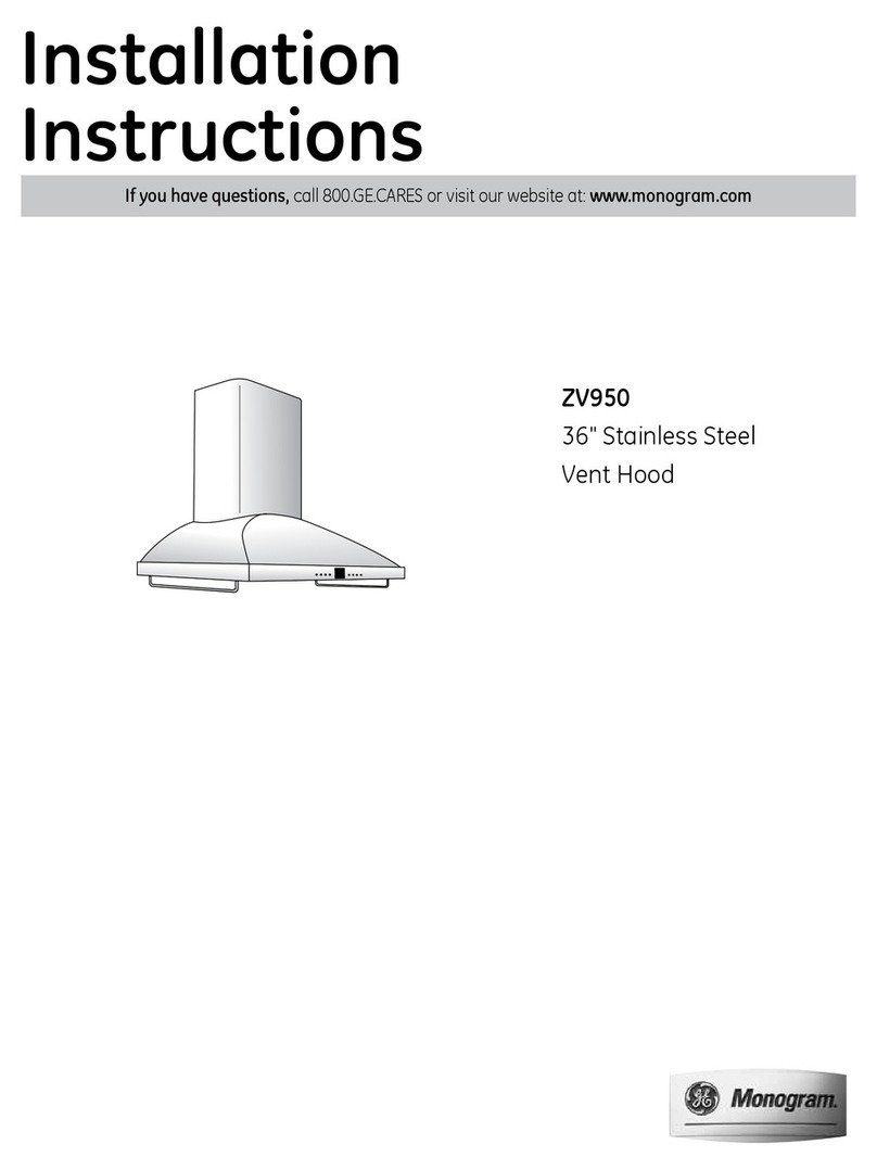
INSTALLATION
INSTRUCTIONS
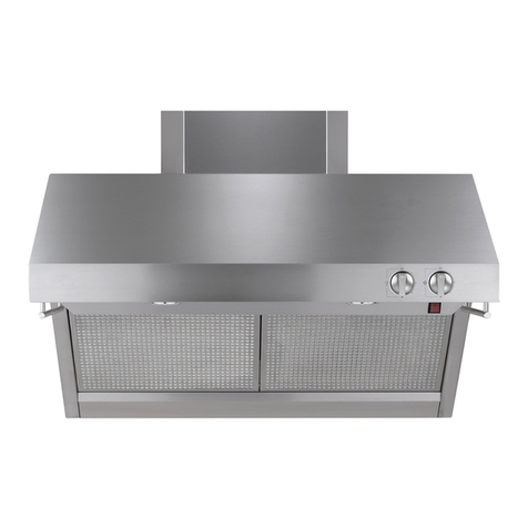
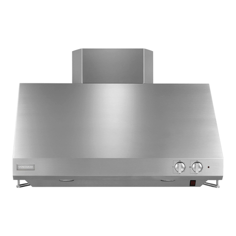
36" Stainless Steel Vent Hood
ZV950
MONOGRAM.COM
231-14900 Rev. 2
Safety Information
READ AND SAVE THESE INSTRUCTIONS
BEFORE YOU BEGIN
Read these instructions completely and carefully.
Ŷ
IMPORTANT — Save these instructions
for local inspector’s use.
Ŷ
IMPORTANT — Observe all governing
codes and ordinances.
ŶNote to Installer — Be sure to leave these
instructions with the Consumer.
ŶNote to Consumer — Keep these instructions with
your Owner’s Manual for future reference.
ŶSkill Level — Installation of this appliance requires
basic mechanical and electrical skills.
ŶCompletion Time — 1 to 3 Hours.
Ŷ3URSHULQVWDOODWLRQLVWKHUHVSRQVLELOLW\RIWKH
LQVWDOOHU3URGXFWIDLOXUHGXHWRLPSURSHULQVWDOODWLRQ
is not covered under the warranty.
Ŷ)RU0RQRJUDPORFDOVHUYLFHLQ\RXUDUHDYLVLW
monogram.com.
Ŷ)RU0RQRJUDPVHUYLFHLQ&DQDGDYLVLWmonogram.ca
Ŷ)RU0RQRJUDP3DUWVDQG$FFHVVRULHVYLVLW
monogram.com/use-and-care/parts.
CAUTION Due to the weight and size of these
vent hoods and to reduce the risk of personal injury
RUGDPDJHWRWKHSURGXFW TWO PEOPLE ARE
REQUIRED FOR PROPER INSTALLATION.
ATTENTION À cause du poids et de la taille de
ces hottes et pour reduire le risque de blessures et de
GRPPDJHV IL FAUT DEUX PERSONNES POUR FAIRE
L’INSTALLATION CORRECTEMENT.
WARNING To reduce the risk of fire or electrical
VKRFNGRQRWXVHWKLVUDQJHKRRGZLWKDQ\H[WHUQDO
VROLGVWDWHVSHHGFRQWUROGHYLFH$Q\VXFKDOWHUDWLRQ
from original factory wiring could result in damage to
the unit and/or create an electrical safety hazard.
AVERTISSEMENT
3RXUUpGXLUHOHULVTXHG¶LQFHQGLH
RXGHFKRFpOHFWULTXHLOQHIDXWSDVXWLOLVHUFHWWHKRWWH
DYHFXQUpJXODWHXUGHYLWHVVHpOHFWURQLTXHH[WHUQH7RXWH
modification de ce type du branchement d’usine peute
HQGRPPDJHUO¶DSSDUHLORXFUpHUXQULVTXHGHFKRFpOHFWULTXH
TO REDUCE THE RISK OF FIRE, USE ONLY
METAL DUCTWORK.
WARNING 725('8&(7+(5,6.2)),5(
(/(&75,&$/6+2&.25,1-85<723(56216
2%6(59(7+()2//2:,1*
$8VHWKLVXQLWRQO\LQWKHPDQQHULQWHQGHGE\WKH
PDQXIDFWXUHU,I\RXKDYHDQ\TXHVWLRQVFRQWDFW
the manufacturer.
%%HIRUHVHUYLFLQJRUFOHDQLQJWKHXQLWVZLWFKWKH
power off at the service panel and lock the service
disconnecting means to prevent the power from
EHLQJVZLWFKHGRQDFFLGHQWDOO\:KHQWKHVHUYLFH
GLVFRQQHFWLQJPHDQVFDQQRWEHORFNHGVHFXUHO\
IDVWHQDSURPLQHQWZDUQLQJGHYLFHVXFKDVDWDJ
to the service panel.
AVERTISSEMENT
32855e'8,5(/(5,648(
'¶,1&(1',('(&+2&e/(&75,48(28'(%/(6685(6
,/)$872%6(59(5/(65(*/(668,9$17(6
$ 
8WLOLVH]FHWDSSDUHLOXQLTXHPHQWGHODPDQLpUpSUpYXHSDU
OHIDEULFDQW(QFDVGHTXHVWLRQFRQVXOWH]OHIDEULFDQW
% $YDQWWRXWHLQWHUYHQWLRQRXQHWWR\DJHFRXSH]
O¶DOLPHQWDWLRQpOHFWULTXHDXGLVMRQFWHXUHWYHUURXLOOH]OH
SDQQHDXGXGLVMRQFWHXUSRXUpYLWHUODPLVHVRXVWHQVLRQ
accidentelle. S’il n’est pas possible de verrouiller le
SDQQHDXGXGLVFRQFWHXUDWWDFKH]XQSODFDUGRXXQH
pWLTXHWWHWUqVYLVLEOHDXSDQQHDX
Ŷ)RUJHQHUDOYHQWLODWLQJXVHRQO\'RQRWXVHWRH[KDXVW
KD]DUGRXVRUH[SORVLYHPDWHULDOVRUYDSRUV
Ŷ6WUXFWXUDOIUDPLQJLQVWDOODWLRQZRUNDQGHOHFWULFDO
wiring must be done by qualified person(s). In
accordance with all applicable codes and standards
including fire-rated construction.
Ŷ6XIILFLHQWDLULVQHHGHGIRUSURSHUFRPEXVWLRQDQG
H[KDXVWLQJRIJDVHVWKURXJKWKHIOXHFKLPQH\RIIXHO
EXUQLQJHTXLSPHQWWRSUHYHQWEDFNGUDIWLQJ)ROORZ
the heating equipment manufacturer’s guidelines
DQGVDIHW\VWDQGDUGVVXFKDVWKRVHSXEOLVKHGE\
WKH1DWLRQDO)LUH3URWHFWLRQ$VVRFLDWLRQ1)3$WKH
$PHULFDQ6RFLHW\IRU+HDWLQJ5HIULJHUDWLRQDQG$LU
&RQGLWLRQLQJ(QJLQHHUV$6+5$(DQGWKHORFDOFRGH
DXWKRULWLHV:KHQDSSOLFDEOHLQVWDOODQ\PDNHXS
(replacement) air system in accordance with local
building code requirements.
Ŷ/RFDOFRGHVYDU\,QVWDOODWLRQRIHOHFWULFDOFRQQHFWLRQV
and grounding must comply with applicable codes.
,QWKHDEVHQFHRIORFDOFRGHVWKHYHQWVKRXOGEH
LQVWDOOHGLQDFFRUGDQFHZLWK1DWLRQDO(OHFWULFDO&RGH
$16,1)3$RUODWHVWHGLWLRQ
CAUTION To reduce risk of fire and to properly
H[KDXVWDLUEHVXUHWRGXFWDLURXWVLGH²GRQRWYHQW
H[KDXVWDLULQWRVSDFHVZLWKLQZDOOVRUFHLOLQJVRULQWR
DWWLFVFUDZOVSDFHVRUJDUDJHV
ATTENTION Il faut prendre soin d’installer un conduit
YHUVO¶H[WpULHXUSRXUUpGXLUHOHULVTXHG¶LQFHQGLHHWSRXYRLU
pYDFXHUO¶DLUFRUUHFWHPHQW,OQHIDXWSDVpYDFXHUO¶DLUGDQV
O¶HVSDFHHQWUHOHVSDURLVG¶XQPXUXQSODIRQGRXXQJUHQLHU
un espace sanitaire ou un garage.
31-14900 Rev. 2 3
PRODUCT DIMENSIONS AND CLEARANCES
36" Vent Hood Installation Combinations
This Stainless Steel Hood can be installed over any
0RQRJUDPFRRNWRSLQFOXGLQJWKH3URIHVVLRQDO
UDQJHWRSDQGRUUDQJH
7KHYHQWKRRGPXVWEHLQVWDOOHGPLQDQGPD[
DERYHWKHFRRNLQJVXUIDFH7KHKRRGLQVWDOODWLRQKHLJKW
IURPWKHFRRNLQJVXUIDFHWRWKHERWWRPRIWKHKRRG
depends upon ceiling height.
&RRNLQJVXUIDFHWRERWWRPRIKRRGVKRXOGEH
PD[IRUIWFHLOLQJKHLJKW
WRIRUIWFHLOLQJKHLJKW
PLQIRUIWFHLOLQJKHLJKW
3ODQWKHLQVWDOODWLRQKHLJKWFDUHIXOO\WRDYRLGXQVLJKWO\
gaps above the hood.
7KLVKRRGPXVWEHLQVWDOOHGPLQDERYHD0RQRJUDP
3URIHVVLRQDO&RRNWRSRU5DQJH&HLOLQJKHLJKWIRUWKLV
LQVWDOODWLRQFRPELQDWLRQPXVWEHDWOHDVWKLJK
NOTE: The supplied 2-piece duct cover is adjustable to
¿WIWWRIWFHLOLQJV)RUFHLOLQJKHLJKWVJUHDWHUWKDQ
IWDQGXSWRIWRUGHU=;6'66VWDLQOHVVVWHHO
duct cover accessory.
Design Information
10"
*Height
to Ceiling
35-5/8"
25"
7KHVXSSOLHGGXFWFRYHU¿WVIWWRIWFHLOLQJV
Installation
Height Depending
on Ceiling Height
36" Min.
ZV950SDSS Duct
Cover Dimensions
ZX14SDSS Duct Cover
Dimensions
CONTENTS
Design Information
3URGXFW'LPHQVLRQVDQG&OHDUDQFHV ........................ 3–4
2SWLRQDO$FFHVVRULHV ..................................................... 4
Installation Preparation
$GYDQFH3ODQQLQJ
'XFWZRUN)UDPLQJ ...................................................... 5
3RZHU6XSSO\ ................................................................ 5
'XFW)LWWLQJV................................................................... 
Tools and Materials Required........................................ 
5HPRYHWKH3DFNDJLQJ ................................................. 
Check Installation Hardware.......................................... 
'XFWZRUN:LULQJ/RFDWLRQV ........................................... 
Installation Instructions
6WHS,QVWDOO)UDPLQJIRU+RRG6XSSRUW ...................... 
6WHS,QVWDOO0RXQWLQJ%UDFNHWV .................................. 
6WHS,QVWDOO'XFW%UDFNHW ........................................... 
6WHS,QVWDOOWKH+RRG ............................................... 
6WHS&RQQHFW'XFWZRUN ........................................... 
6WHS&RQQHFW(OHFWULFDO ........................................... 11
6WHS,QVWDOO'XFW&RYHUV .......................................... 11
6WHS,QVWDOO)LOWHUV .................................................... 11
6WHS)LQDOL]H,QVWDOODWLRQ.......................................... 11
431-14900 Rev. 2
PRODUCT DIMENSIONS AND
CLEARANCES (Cont.)
Using Duct Cover Accessories
$'XFW&RYHU$FFHVVRU\PD\EHUHTXLUHGIRU\RXU
hood installation height. Use this chart to determine
installation height and accessory for your ceiling
height.
Design Information
%DVHGRQFRXQWHUWRSKHLJKW
7KHVHULDOSODWHLVORFDWHGEHKLQGWKHUHPRYDEOH¿OWHUV
ZV950SDSS Installation Heights
Actual Ceiling
Height
* Possible Hood
Installation Height
Duct
Cover
 
 
 WR
 WR
 WR
 WR
 WR
 WR
 WR
 WR
 WR
 WR
 WR
 WR
 WR
 WR
 WR
 WR
 WR
 PLQ
 PLQ
 PLQ
 PLQ
 PLQ
 PLQ


PLQ
=;6'66 6833/,('
OPTIONAL ACCESSORIES
Using Duct Cover Accessories
=;6'66RSWLRQDOVWDLQOHVVVWHHOGXFWFRYHULV
DYDLODEOHIRUFHLOLQJKHLJKWVJUHDWHUWKDQIWDQGXS
to 14 ft.
Order the optional duct cover at the same time as the
vent hood and have on site before installation. This
kit contains hardware required for installation. This kit
contains installation hardware.
NOTE: Duct covers must be installed as shown in
this book. Do not “build-in” the duct cover. If service is
UHTXLUHGWKHGXFWFRYHUPXVWEHUHPRYHGWRDFFHVV
hood components.
31-14900 Rev. 2 5
Installation Preparation
ADVANCE PLANNING
Ŷ'HWHUPLQHWKHH[DFWORFDWLRQRIWKHYHQWKRRG
Ŷ3ODQWKHURXWHIRUYHQWLQJH[KDXVWWRWKHRXWGRRUV
Ŷ8VHWKHVKRUWHVWDQGVWUDLJKWHVWGXFWURXWHSRVVLEOH)RU
VDWLVIDFWRU\SHUIRUPDQFHGXFWUXQVKRXOGQRWH[FHHG
IWHTXLYDOHQWOHQJWKIRUDQ\GXFWFRQILJXUDWLRQV
Ŷ5HIHUWR³'XFW)LWWLQJV´FKDUWRQSDJHWRFRPSXWH
WKHPD[LPXPSHUPLVVLEOHOHQJWKIRUGXFWUXQVWRWKH
outdoors.
Ŷ:KHQDSSOLFDEOHLQVWDOODQ\PDNHXSUHSODFHPHQW
air system in accordance with local building code
requirements. Visit Monogram.com for available
makeup air solutions.
CAUTION To reduce risk of fire and to properly
H[KDXVWDLUEHVXUHWRGXFWDLURXWVLGH²GRQRWYHQW
H[KDXVWDLULQWRVSDFHVZLWKLQZDOOVRUFHLOLQJVRULQWR
DWWLFVFUDZOVSDFHVRUJDUDJHV
ATTENTION Il faut prendre soin d’installer un conduit vers
O¶H[WpULHXUSRXUUpGXLUHOHULVTXHG¶LQFHQGLHHWSRXYRLUpYDFXHU
O¶DLUFRUUHFWHPHQW,OQHIDXWSDVpYDFXHUO¶DLUFRUUHFWHPHQW,OQH
IDXWSDVpYDFXHUO¶DLUGDQVO¶HVSDFHHQWUHOHVSDURLVG¶XQPXUXQ
SODIRQGRXXQJUHQLHUXQHVSDFHVDQLWDLUHRXXQJDUDJH
Ŷ8VHPHWDOGXFWZRUNRQO\7KHVHKRRGVPXVWXVH
´URXQGGXFW,WFDQWUDQVLWLRQWR´[´UHGXFLQJ
WKHPD[LPXPHTXLYDOHQWGXFWOHQJWKWR
IHHW
Ŷ,QVWDOODZDOOFDSZLWKGDPSHURUURRIFDSDWWKH
H[WHULRURSHQLQJ2UGHUWKHZDOORUURRIFDSDQGDQ\
transition needed in advance.
Wall Framing for Adequate Support
Ŷ7KLVYHQWKRRGLVKHDY\$GHTXDWHVWUXFWXUDOVXSSRUW
must be provided. The hood must be secured to
YHUWLFDOVWXGVLQWKHZDOORUWRDKRUL]RQWDOVXSSRUW
6HHSDJH
Ŷ:HVWURQJO\UHFRPPHQGWKDWWKHYHQWKRRGZLWKGXFW
cover be on site before final framing and wall finishing.
This will also help to accurately locate the ductwork
and electrical service.
POWER SUPPLY
IMPORTANT – (Please read carefully)
WARNING )253(5621$/6$)(7<7+,6
$33/,$1&(0867%(3523(5/<*5281'('
AVERTISSEMENT
3285'(65$,6216'(
6e&85,7e&(7$33$5(,/'2,7Ç75(&255(&7(0(17
0,6¬/$7(55(
Remove house fuse or open circuit breaker before
beginning installation.
'RQRWXVHDQH[WHQVLRQFRUGRUDGDSWHUSOXJZLWKWKLV
DSSOLDQFH)ROORZ1DWLRQDOHOHFWULFDOFRGHVRUSUHYDLOLQJ
local codes and ordinances.
Electrical supply
7KHVHYHQWKRRGVPXVWEHVXSSOLHGZLWK9+]
DQGFRQQHFWHGWRDQLQGLYLGXDOSURSHUO\JURXQGHG
EUDQFKFLUFXLWDQGSURWHFWHGE\DRUDPSFLUFXLW
breaker or time delay fuse.
Ŷ:LULQJPXVWEHZLUHZLWKJURXQG
Ŷ,IWKHHOHFWULFDOVXSSO\GRHVQRWPHHWWKHDERYH
UHTXLUHPHQWVFDOODOLFHQVHGHOHFWULFLDQEHIRUH
proceeding.
Ŷ5RXWHKRXVHZLULQJWKURXJKFRQGXLWDVFORVHWRWKH
LQVWDOODWLRQORFDWLRQDVSRVVLEOHLQWKHFHLOLQJRUEDFN
wall.
Ŷ&RQQHFWWKHKRRGZLULQJWRWKHKRXVHZLULQJLQ
accordance with local codes.
Grounding instructions
The grounding conductor must be connected to a
JURXQGHGPHWDOSHUPDQHQWZLULQJV\VWHPRUDQ
equipment-grounding terminal or lead on the hood.
WARNING The improper connection of the
equipment-grounding conductor can result in a risk
of electric shock. Check with a qualified electrician or
service representative if you are in doubt whether the
appliance is properly grounded.
AVERTISSEMENT
Le mauvais branchement du fil de
PLVHjODWHUUHSHXWFDXVHUXQFKRFpOHFWULTXH(QFDVGHGRXWH
FRQVXOWHUXQpOHFWULFLHQTXDOLILpRXXQWHFKQLFLHQSRXUGpWHUPLQHU
si l’appareil est à la terre.
31-14900 Rev. 2
Installation Preparation
DUCT FITTINGS
This Hood Must Use an
” Round Duct.
It Can Transition to a
3-1/4” x 12” Duct.
8VHWKLVFKDUWWRFRPSXWHPD[LPXP
permissible lengths for duct runs to
outdoors.
NOTE:'RQRWH[FHHGPD[LPXP
permissible equivalent lengths!
Maximum duct length:
100 ft. for range hoods.
Flexible ducting:
,IIOH[LEOHPHWDOGXFWLQJLVXVHGDOO
the equivalent feet values in the
WDEOHVKRXOGEHGRXEOHG7KHIOH[LEOH
metal duct should be straight and
VPRRWKDQGH[WHQGHGDVPXFKDV
possible.
'2127XVHIOH[LEOHSODVWLFGXFWLQJ
NOTE:$Q\KRPHYHQWLODWLRQ
V\VWHPVXFKDVDYHQWLODWLRQKRRG
may interrupt the proper flow of
FRPEXVWLRQDLUDQGH[KDXVWUHTXLUHG
E\ILUHSODFHVJDVIXUQDFHVJDV
water heaters and other naturally
vented systems. To minimize the
chance of interruption of such
QDWXUDOO\YHQWHGV\VWHPVIROORZWKH
heating equipment manufacturer’s
guidelines and safety standards
VXFKDVWKRVHSXEOLVKHGE\1)3$
DQG$6+5$(:KHQDSSOLFDEOH
install any makeup (replacement)
air system in accordance with
local building code requirements.
Visit Monogram.com for available
makeup air solutions.
Equivalent
Duct Piece Dimensions
Equivalent
Length*
Quantity
Used
Total
Equivalent
Length
5RXQGVWUDLJKW 1 ft.
(per foot length)
´[´VWUDLJKW 1 ft.
(per foot length)
HOERZ IW
HOERZ IW
»´[´
HOERZ
43 ft.
´[´RU
HOERZ
IW
´[´
IODWHOERZ
IW
´URXQGWR
´[´WUDQVLWLRQ
2 ft.
´[´WR´
round transition
5 ft.
´URXQGWR´[´
WUDQVLWLRQHOERZ
IW
´[´WR´
URXQGWUDQVLWLRQHOERZ
13 ft.
Round wall cap
with damper
32 ft.
´[´ZDOOFDS
with damper
IW
Round roof cap 44 ft
$FWXDOOHQJWKRIVWUDLJKWGXFWSOXVGXFWILWWLQJHTXLYDOHQW(TXLYDOHQW
length of duct pieces are based on actual tests conducted by
*($SSOLDQFHV(YDOXDWLRQ(QJLQHHULQJDQGUHIOHFWUHTXLUHPHQWVIRU
good venting performance with any ventilation hood. Total Duct Run
31-14900 Rev. 2 
REMOVE THE PACKAGING
The hood is shipped secured to a shipping board with (4)
screws. Remove the 4 screws. Two screws are located
at the top of the hood. Two are located at the bottom of
the hood behind the grease filters.
$VKLSSLQJEUDFNHWZKLFKVXSSRUWVWKHEORZHUPXVW
DOVREHUHPRYHG,WLVVHFXUHGZLWKWZRVFUHZV$OOVFUHZ
LPSUHVVLRQVDUH3KLOOLSV
Ŷ5HPRYHDOOSDFNDJLQJWKHGXFWFRYHUVDQG
accessories.
Ŷ/LIWWKHKRRGRXWRIWKHFDUWRQ
Ŷ5HPRYHDQGSURSHUO\GLVFDUGDOOSODVWLFZUDSSLQJ
Ŷ5HPRYHMXQFWLRQER[FRYHU
Ŷ,QVWDOOVWUDLQUHOLHILQWRMXQFWLRQER[FRYHU
Installation Preparation
Top Of Hood
Top Shipping Screws
Junction
Box
Shipping Board
Remove Bottom Shipping
Screws and Shipping Bracket
TOOLS AND MATERIALS REQUIRED (NOT SUPPLIED)
Ŷ7DSHPHDVXUH
Ŷ.QLIH
Ŷ6SLULWOHYHO
Ŷ:LUHFXWWHUVWULSSHU
Ŷ:LUHQXWV
Ŷ(OHFWULFGULOOZLWKDQGELWV
Ŷ3KLOOLSVDQGIODWEODGHVFUHZGULYHUV
Ŷ+DPPHU
Ŷ3OLHUV
Ŷ6DIHW\JODVVHV
Ŷ'XFWWDSH
Ŷ7DSHWRPRXQWWHPSODWH
Ŷ*ORYHVWRSURWHFWDJDLQVWVKDUSHGJHV
Ŷ9+]RU$PSZLUHZLWKJURXQG3URSHUO\
grounded branch circuit
Ŷ6WUDLQUHOLHIIRUMXQFWLRQFRYHU
ŶURXQGPHWDOGXFWOHQJWKWRVXLWLQVWDOODWLRQ
31-14900 Rev. 2
CHECK INSTALLATION HARDWARE
/RFDWHWKHKDUGZDUHDFFHVVRU\ER[SDFNHGZLWKWKH
hood and check contents.
DUCTWORK, WIRING LOCATIONS
'HWHUPLQHWKHH[DFWORFDWLRQRIWKHYHQWKRRG
Ŷ/RFDWHWKHWHPSODWHSDFNHGZLWKWKHOLWHUDWXUH
±0HDVXUHIURPWKHÀRRUWRWKHWRSRI
WKHFRRNLQJVXUIDFH$GGRURWKHU
recommended space) from the cooking surface to
the bottom of the hood. Mark that location.
– Use a level to draw a straight pencil line on the wall.
– Tape the template in position along the penciled
OLQH&+(&.72%(685(7+(7(03/$7(,6
LEVEL.
Ceiling ducting:
,IGXFWZRUNZLOOYHQWVWUDLJKWXSWRWKHFHLOLQJ
Ŷ8VHDOHYHOWRGUDZDOLQHVWUDLJKWXSIURPWKH
centerline on the template to the ceiling.
Ŷ0HDVXUHIURPWKHEDFNZDOOWRWKH
FHQWHUOLQHRIDKROHRQWKHFHLOLQJ
NOTE: ,IGU\ZDOOLVQRWSUHVHQWDGGGU\ZDOO
WKLFNQHVVWRWKHGLPHQVLRQ
Wall Ducting:
,IGXFWZRUNZLOOYHQWWRWKHUHDU
Ŷ8VHWKHOHYHOWRGUDZDOLQHVWUDLJKWXSIURPWKH
centerline on the template.
Ŷ0HDVXUHDWOHDVWDERYHWKHWRSPRXQWLQJ
bracket holes shown on the template to the
FHQWHUOLQHRIDQGLDGXFWKROH+ROHPD\EH
elongated for duct elbow.)
HOUSE WIRING LOCATION:
Ŷ7KHMXQFWLRQER[LVORFDWHGRQWKHWRSRIWKHKRRG
at the back right side.
Ŷ5RXWHKRXVHZLULQJDVFORVHWRWKHFHLOLQJORFDWLRQ
DVSRVVLEOHWKURXJKWKHFHLOLQJVRႈWRUEDFNZDOO
:LULQJVKRXOGHQWHUDWOHDVWDERYHWKHEUDFNHW
RQWKHULJKWVLGHQROHVVWKDQDERYHWKH
SODQQHGORZHUHGJHRIKRRGDQGLGHDOO\WRWKH
right of planned ductwork.)
• Drill 1/8" Pilot Holes For Mounting Brackets.
Centerline
8" Min. Above
Top Mounting
Bracket Holes
6-1/4"
Centerline To Wall
FOR WALL VENT DUCT
FOR CEILING
VENT DUCTING
Align edge 25-1/2" above Cooking Surface.
17-1/2" 2-5/32"
C
L
5-7/8"
8-1/2" Dia. Hole
• Drill 1/8" Pilot Holes For Mounting Brackets.
Align edge 25-1/2" above Cooking Surface.
13-9/16" 2-5/32"
C
L
C
L
C
L
5-7/8"
Installation Preparation
2 Large
)ODW:DVKHUV
3KLOOLSV+HDG
Decorative Screws
6WDLQOHVV6WHHO*UHDVH)LOWHUV
:RRG
Screws
:DOO0RXQW7HPSODWH
2 Mounting Brackets with 4
+H[+HDG/HYHOLQJ6FUHZV
Duct Cover Bracket
:DOO
)DVWHQHUV
2-piece
Decorative Duct Cover
(dimension shown
for reference only)
16"
23"
11"
24"
31-14900 Rev. 2 
2 INSTALL MOUNTING BRACKET
This vent hood must be secured to the horizontal
support or wall studs.
Ŷ:LWKWKHWHPSODWHWDSHGLQSODFHXVHDSXQFKWR
mark all mounting screw locations.
Ŷ'ULOO´SLORWKROHVDWWKHSXQFKHGORFDWLRQV
Ŷ5HPRYHWKHWHPSODWH
Ŷ7KHVXSSRUWEUDFNHWKROHVPXVWHQWHUVWXGVRUWKH
horizontal support.
Ŷ6HFXUHWKHPRXQWLQJEUDFNHWVWRWKHZDOOVWXGVZLWK
wood screws provided.
1 INSTALL FRAMING FOR HOOD
SUPPORT
IMPORTANT: Framing must be capable of
supporting 100 lbs.
,IGU\ZDOOLVSUHVHQWPDUNWKHVFUHZKROHORFDWLRQVIRU
the top mounting brackets. Remove the template.
Ŷ&XWDZD\HQRXJKGU\ZDOOWRH[SRVHYHUWLFDOVWXGV
at the bracket location indicated on the template.
Ŷ,QVWDOODKRUL]RQWDOVXSSRUWDWOHDVW[EHWZHHQ
two wall studs at the mounting screw location. The
horizontal support must be flush with the room
side of the studs. Use cleats behind both sides of
the support to secure to wall studs.
Ŷ5HLQVWDOOGU\ZDOO
Installation Instructions
Centerline of
Installation
Space
8" Min. Opening for Ductwork
View From Rear
Cleats
1" x 6" Min.
Mounting
Support
NOTE: 6FUHZV³$´DQG
“B” are pre-assembled
onto the brackets. Do not
remove these screws.
Screws
“B”
Screws
“A”
3 INSTALL DUCT BRACKET
The duct bracket must be installed against the ceiling.
This bracket will hold the decorative duct cover in
place at the top.
ŶInstall the 2 small screws into the sides of the duct
EUDFNHW5HPRYHWKHVFUHZV3UHWDSSLQJWKHKROHV
ZLOOLQVXUHHDVHRI¿QDOLQVWDOODWLRQ
Secure the bracket to the ceiling and wall:
Ŷ0DUNWKHVFUHZKROHORFDWLRQV
Ŷ'ULOOSLORWKROHVLQPDUNHGEUDFNHWORFDWLRQ
Ŷ,ISLORWKROHVGRQRWHQWHUVWXGVHQODUJHWKHKROHVWR
DQGLQVWDOOZDOOIDVWHQHUDQFKRUV
Ŷ'ULYHVFUHZVE\KDQGLQWRWKHIDVWHQHUVWRDOORZ
DQFKRUVWRH[SDQG5HPRYHWKHVFUHZV
Ŷ6HFXUHWKHEUDFNHWWRWKHFHLOLQJDQGZDOOZLWKZRRG
screws and/or fasteners.
Pre-Tap
Side
Screw
Pre-Tap
Side
Screw
 31-14900 Rev. 2
5 CONNECT DUCTWORK
Ŷ,QVWDOOGXFWZRUNPDNLQJFRQQHFWLRQVLQGLUHFWLRQRI
airflow as illustrated.
Ŷ3XVKGXFWRYHUWKHH[KDXVWRXWOHWXQWLOLWUHDFKHVWKH
duct stops.
Ŷ6HFXUHMRLQWVLQGXFWZRUNZLWKVKHHWPHWDOVFUHZV
Ŷ:UDSDOOGXFWMRLQWVZLWKGXFWWDSHIRUDQDLUWLJKW
seal.
Ŷ8VHGXFWWDSHWRVHDOWKHIODQJHFRQQHFWLRQ
CAUTION Do not use sheet metal screws at the
hood flange connection. Doing so will prevent proper
damper operations. Seal connection with tape only.
ATTENTION Il ne faut pas utiliser de vis
DXWRUDXUGHXVHVjODFRQQH[LRQGXFROOHWGHODKRWWH&HFL
HPSrFKHUDLWOHERQIRQFWLRQQHPHQWGXUHJLVWUH1¶XWLOLVHU
TXHGXUXEDQDGKpVLISRXUDVVXUHUO¶pWDQFKpLWpGXUDFFRUG
4 INSTALL THE HOOD
3ODFHWKHKRRGRQWKHEUDFNHWVDQGVOLGHOHIWRUULJKWWR
center.
$GMXVWWKHLQVWDOODWLRQOHYHOQHVVE\WLJKWHQLQJ
RUORRVHQLQJWKHVFUHZV³$´DWWKHERWWRPRIWKH
brackets.
2. Mark the 2 lower mounting holes.
3. Remove the hood from the wall.
4. Drill a pilot hole in each lower mounting hole
location. The two lower holes can be enlarged to
LIWKH\GLGHQWHUVWXGV7DSDQFKRUVIRUZDOO
fasteners into the bottom holes. Screws should be
inserted by hand into the fasteners to allow anchors
WRH[SDQGDJDLQVWWKHZDOOPDWHULDO5HPRYHWKH
VFUHZVIRU¿QDOLQVWDOODWLRQ
5. Replace the hood on the mounting brackets.
8VLQJWZRODUJHÀDWZDVKHUVVXSSOLHGLQVWDOOZRRG
screws or wall fastener screws.
7LJKWHQVFUHZV³%´ORFDWHGDWWKHWRSRIWKH
mounting bracket against the hood to clamp the
position. Do not overtighten screws.
Bracket Tabs
Screws
“B”
Screws
“A”
Installation Instructions
Screw
Duct Tape
Over Seam
and Screw
Air Flow
Duct Tape
Over Flange
Duct Stops
31-14900 Rev. 2 11
6 CONNECT ELECTRICAL
9HULI\WKDWSRZHULVWXUQHGRႇDWWKHVRXUFH
WARNING If house wiring is not 2-wire with
DJURXQGZLUHDJURXQGPXVWEHSURYLGHGE\WKH
LQVWDOOHU:KHQKRXVHZLULQJLVDOXPLQXPEHVXUH
WRXVH8/DSSURYHGDQWLR[LGDQWFRPSRXQGDQG
aluminum-to-copper connectors.
AVERTISSEMENT
Si la maison n’est pas câblee avec
GHX[ILOVHWXQILOGHWHUUHO¶LQVWDOODWHXUGRLWLQVWDOOHUXQILOGH
WHUUH4XDQGOHVILOVVRQWHQDOXPLQLXPLOIDXWSUHQGUHVRLQ
d’utiliser des connecteurs aluminium à cuivre avec une pâte
DQWLR[\GDQWHDSSURXYpHSDU8/
Ŷ,QVHUWKRXVHZLULQJWKURXJKVWUDLQUHOLHIDQGWLJKWHQ
Ŷ&RQQHFWZKLWHOHDGVWREUDQFKFLUFXLWZKLWHOHDG
Ŷ&RQQHFWEODFNOHDGVWREUDQFKFLUFXLWEODFNOHDG
Ŷ&RQQHFWJUHHQ\HOORZOHDGVWREUDQFKFLUFXLWJUHHQ
lead or bare ground lead.
Ŷ6HFXUHDOOFRQQHFWLRQVZLWKZLUHQXWVRQHDFK
electrical connector.
Ŷ3XVKZLUHVLQWRMXQFWLRQER[DQGUHSODFHFRYHU%H
sure wires are not pinched.
9 FINALIZE INSTALLATION
Ŷ5HPRYHWKHSURWHFWLYHILOPFRYHULQJWKHFRQWURO
SDQHORQWKHIURQWIDFHRIWKHKRRGDQGDQ\RWKHU
packaging materials.
Ŷ5HIHUWRWKH2ZQHU¶V0DQXDOIRURSHUDWLQJ
instructions.
8 CONNECT ELECTRICAL
Ŷ5HPRYHSURWHFWLYHILOPRQWKHILOWHUV
Ŷ7LSWKHILOWHULQWRWKHVORWVDWWKHUHDURIWKHRSHQLQJ
Lift the filter and pull the knob forward until the filter
rests on the slots.
Ŷ,QVWDOODOOJUHDVHILOWHUV
Ŷ7RUHPRYHWKHILOWHUVJUDVSWKHNQRESXVKWKHILOWHU
towards the rear and tilt downwards.
Ŷ,IWKH&OHDQ)LOWHU5HPLQGHULVJORZLQJUHGDIWHU
ILOWHUVDUHLQVWDOOHGEHVXUHWRFKHFNWKHOHIWVLGH
filter is making contact with the filter switch.
7 INSTALL DUCT COVERS
Ŷ3ODFHWKHGHFRUDWLYH
duct covers on top
of the hood.
Ŷ,QVHUWWKHORZHU
portion of the duct
cover into the
impressions on the
top of the hood.
Ŷ([WHQGWKHLQQHU
duct upwards to the
ceiling bracket.
Ŷ6HFXUHWKHGXFWFRYHUWRWKHEUDFNHWZLWKWKHVPDOO
3KLOOLSVVFUHZVSURYLGHG
Installation Instructions
Mounting Screws
Bottom
Notches
NOTE::KLOHSHUIRUPLQJLQVWDOODWLRQVGHVFULEHGLQWKLVERRN
safety glasses or goggles should be worn.
)RU0RQRJUDP®ORFDOVHUYLFHLQ\RXUDUHDYLVLW
monogram.com.
NOTE:3URGXFWLPSURYHPHQWLVDFRQWLQXLQJHQGHDYRUDW
0RQRJUDP$SSOLDQFHV7KHUHIRUHPDWHULDOVDSSHDUDQFHDQG
specifications are subject to change without notice.
31-14900 Rev. 3
10-19 GEA
Printed in Italy

Other manuals for ZV950

3

This manual suits for next models

1

Other Monogram Ventilation Hood manuals

Monogram ZV800 User manual

Monogram

Monogram ZV800 User manual

Monogram ZV48R User manual

Monogram

Monogram ZV48R User manual

Monogram ZV950 User manual

Monogram

Monogram ZV950 User manual

Monogram Monogram Vent hood User manual

Monogram

Monogram Monogram Vent hood User manual

Monogram ZV850 User manual

Monogram

Monogram ZV850 User manual

Monogram ZV1050 User manual

Monogram

Monogram ZV1050 User manual

Monogram ZVW1360 User manual

Monogram

Monogram ZVW1360 User manual

Monogram ZV30 User manual

Monogram

Monogram ZV30 User manual

Monogram ZV1050 User manual

Monogram

Monogram ZV1050 User manual

Monogram ZV900 User manual

Monogram

Monogram ZV900 User manual

Monogram ZV1050 User manual

Monogram

Monogram ZV1050 User manual

Monogram GE Monogram ZVC42 User manual

Monogram

Monogram GE Monogram ZVC42 User manual

Monogram ZV48R User manual

Monogram

Monogram ZV48R User manual

Monogram ZV36 User manual

Monogram

Monogram ZV36 User manual

Monogram ZV48S User manual

Monogram

Monogram ZV48S User manual

Monogram ZV800 User manual

Monogram

Monogram ZV800 User manual

Monogram ZV900 User manual

Monogram

Monogram ZV900 User manual

Monogram ZV421 User manual

Monogram

Monogram ZV421 User manual

Monogram ZX8D13SPXX User manual

Monogram

Monogram ZX8D13SPXX User manual

Monogram ZVC48DTB1 User manual

Monogram

Monogram ZVC48DTB1 User manual

Monogram ZV850 User manual

Monogram

Monogram ZV850 User manual

Monogram ZV48SSJSS User manual

Monogram

Monogram ZV48SSJSS User manual

Monogram ZVC48STSS User manual

Monogram

Monogram ZVC48STSS User manual

Monogram ZV830 User manual

Monogram

Monogram ZV830 User manual

Popular Ventilation Hood manuals by other brands

Amica KHF 694 600 W instruction manual

Amica

Amica KHF 694 600 W instruction manual

Beko CFB 6432 user manual

Beko

Beko CFB 6432 user manual

ELICA SKYDOME H16 A/100 Instruction on mounting and use

ELICA

ELICA SKYDOME H16 A/100 Instruction on mounting and use

Beko CTB 6407 X user manual

Beko

Beko CTB 6407 X user manual

Greenheck DFDR-XXX Installation, operation & maintenance instructions

Greenheck

Greenheck DFDR-XXX Installation, operation & maintenance instructions

Tricity Bendix Visor CH 610 OPERATING AND INSTALLATION Manual

Tricity Bendix

Tricity Bendix Visor CH 610 OPERATING AND INSTALLATION Manual

Amana UXT4236AYS instructions

Amana

Amana UXT4236AYS instructions

DCS DD-30SS Use and care guide

DCS

DCS DD-30SS Use and care guide

Pkm 9004W instruction manual

Pkm

Pkm 9004W instruction manual

Renfert SILENT TS manual

Renfert

Renfert SILENT TS manual

S&P EBB series user manual

S&P

S&P EBB series user manual

Broan 113023 instructions

Broan

Broan 113023 instructions

STATESMAN CHM60SS instruction manual

STATESMAN

STATESMAN CHM60SS instruction manual

Miele PUR 98 D Operating and installation instructions

Miele

Miele PUR 98 D Operating and installation instructions

FALMEC zenith NRS island Instruction booklet

FALMEC

FALMEC zenith NRS island Instruction booklet

AEG Electrolux DD 8821 OPERATING AND INSTALLATION Manual

AEG Electrolux

AEG Electrolux DD 8821 OPERATING AND INSTALLATION Manual

CookMax BKP918ILL Instructions for the installer

CookMax

CookMax BKP918ILL Instructions for the installer

Woodson W.MVS Specification, installation and operation manual

Woodson

Woodson W.MVS Specification, installation and operation manual

manuals.online logo
manuals.online logoBrands
  • About & Mission
  • Contact us
  • Privacy Policy
  • Terms and Conditions

Copyright 2025 Manuals.Online. All Rights Reserved.