Montag GEN 2 - 2218 User manual

Gen 2 Operations Manual
Models 2218, 2208, 2108
P003162- Effective 1-1-2020 thru current
Read manual before operating Montag equipment
MONTAG MANUFACTURING, INC.
3816 461ST AVE
EMMETSBURG, IA 50536
www.montagmfg.com
PH 712-852-4574

2

3
1. Introduction / General Information ........................................................................................... 5
1.1 Introduction ..........................................................................................................................................5
1.2 Hydraulic Requirements .......................................................................................................................5
...........................................................................................................................5
..............................................................................................................................6
..............................................................................................................................7
..............................................................................................................................8
1.7 Warranty Information ............................................................................................................................9
2. Safety ........................................................................................................................................ 10
2.1 Section Overview................................................................................................................................10
2.2 Safety ................................................................................................................................................10
2.2.1 Keep All Guards In Place...........................................................................................................11
2.2.2 Stay Away From Rotating Augers .............................................................................................11
.......................................................................................................11
2.2.4 Avoid Hot Parts ..........................................................................................................................12
2.2.5 Avoid High Pressure Hydraulic Fluid .........................................................................................12
2.2.6 Avoid Flying Object Injuries .......................................................................................................12
2.2.7 Avoid Loss Of Control ................................................................................................................12
2.2.8 Avoid Tipping Cart......................................................................................................................13
2.2.9 Clearance ..................................................................................................................................13
2.2.10 Maintenance ............................................................................................................................13
2.2.11 Hazards From Modifying Your Particulate Metering System....................................................14
2.2.12 Safety Warning Label Locations - 2218 ..................................................................................14
2.2.13 Safety Warning Label Locations - 2208...................................................................................16
2.2.14 Safety Warning Label Locations - 2108...................................................................................17
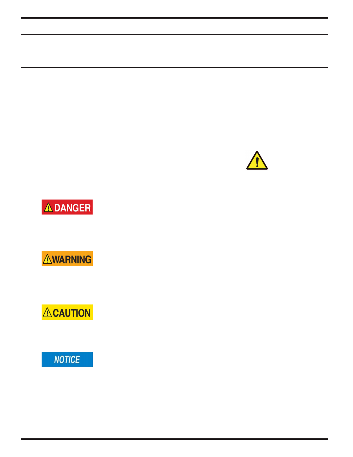
2.2.15 Safety Warning Labels.............................................................................................................18
2.2.16 Safety Decal Care....................................................................................................................22
2.3 Highway And Transportation Operation..............................................................................................22
2.4 Rinse Tank..........................................................................................................................................23
3. Assembly.................................................................................................................................... 24
3.1 Gen 2 2218 System Assembly ..........................................................................................................24
3.1.1 Install Gen 2 Unit On Cart .........................................................................................................24
3.1.2 Install Step and Platform Assembly...........................................................................................24
3.1.3 Install Lights...............................................................................................................................25
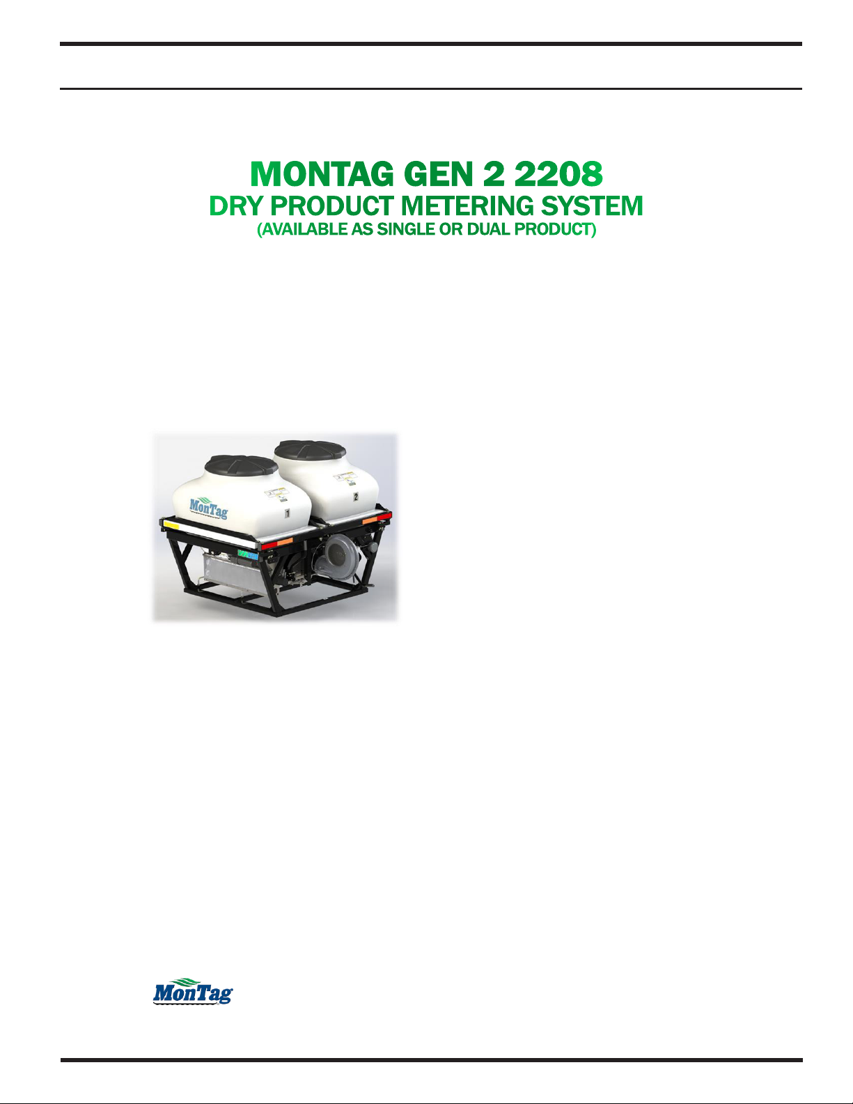
3.2 Gen 2 2208 System Assembly ..........................................................................................................25
3.2.1 Install Gen 2 2208 Unit On Cart ................................................................................................25
3.3 Gen 2 2108 System Assembly ...........................................................................................................26
3.3.1 Install Gen 2 2108 Unit On Implement......................................................................................26
4. Connect Cart To Implement...................................................................................................... 27
...................................................................................................................................27
4.1.1 Connect Hydraulic Hoses ..........................................................................................................27
4.1.2 Connect Air Hoses.....................................................................................................................27
4.1.3 System Air Pressure Adjustment ...............................................................................................28
4.1.4 Controller Set Up .......................................................................................................................28
4.1.5 Hydraulic Slide Gate Operation For Gen 2................................................................................29
4.1.6 Mechanical Slide Gate Controls ................................................................................................29
4.1.7 Fill Gen 2 Tank...........................................................................................................................30
5. Disconnecting From Implement............................................................................................... 31
.................................................................................................31
........................................................................................................31
5.1.2 Disconnect Cart From Implement..............................................................................................31

4
6. Troubleshooting ........................................................................................................................ 32
......................................................................................................................32
...................................................................................................32
6.2 2218 Harness Connection ..................................................................................................................37
6.3 2208 Harness Connection ..................................................................................................................39
6.4 2108 Harness Connection ..................................................................................................................40
7. Routine Maintenance ................................................................................................................ 41
7.1 Section Overview................................................................................................................................41
................................................................................................................41
7.3 Storing the Gen 2 System ..................................................................................................................42
8. Service And Repair.................................................................................................................... 43
.......................................................................................................43
....................................................................................44
............................................................................................45
8.4 Slide Gate Removal / Repair For 2218...............................................................................................46
8.5 Slide Gate Removal / Repair For 2208, 2108.....................................................................................47
8.6 Fan Motor Drive..................................................................................................................................48
9. Appendix .................................................................................................................................... 49
.........................................................................49
..........................................................................................50
.........................................................................................................51
...............................................................................................56
9.4 Hydraulic Schematics .........................................................................................................................58
9.4.1 Hydraulic Schematics - 2218 1 Section Twin Bin ......................................................................58
9.4.2 Hydraulic Schematics - 2218 2 Section Twin Bin ......................................................................59
9.4.3 Hydraulic Schematics - 2218 3 Section Twin Bin ......................................................................60
9.4.4 Hydraulic Schematics - 2218 4 Section Twin Bin ......................................................................61
9.4.5 Hydraulic Schematics - 2208 1 Section Single Product.............................................................62
9.4.6 Hydraulic Schematics - 2208 2 Section Single Product.............................................................63
9.4.7 Hydraulic Schematics - 2208 1 Section Two Product ................................................................64
9.4.8 Hydraulic Schematics - 2208 2 Section Two Product ................................................................65
9.4.9 Hydraulic Schematics - 2208 3 Section Two Product ................................................................66
9.4.10 Hydraulic Schematics - 2208 4 Section Two Product ..............................................................67
9.4.11 Hydraulic Schematics - 2108 1 Section ...................................................................................68
9.4.12 Hydraulic Schematics - 2108 2 Section...................................................................................69
9.4.13 Hydraulic Schematics - 2108 3 Section...................................................................................70
9.4.14 Hydraulic Schematics - 2108 4 Section...................................................................................71
9.5 Scale Connections..............................................................................................................................72
..............................................................................................................73
9.7 Speed Sensor Replacement...............................................................................................................75
9.8 ISOBUS Dry Rate Controller Set-Up Guide .......................................................................................76
9.9 Row Calibration Information ...............................................................................................................82

5
1.1 INTRODUCTION
Read and understand this manual before using your fertilizer/cover crop applicator, and follow all of the safety instructions.
Keep all manuals in a safe place inside your tractor at all times.
fertilizer. 2208 and 2108 machines are generally utilized for cover crop application. In this manual, fertilizer and cover crop/
seed are used interchangeable to describe the function of the machine.
Some components on your Gen 2 metering system may have separate instruction manuals. Where this manual indicates
that you should read another manual, and you do not have that manual, contact your dealer or Montag Manufacturing for
assistance.
Information provided in this manual was current as of the issue date. Montag Manufacturing reserves the right to make
design changes without further notice or liability.
This manual covers 2218, 2208, and 2108 models. While there are dierences between these models, many
aspects of safety and operation are shared between them. Please be aware that there may be minor dierences
between the images shown in this manual and the physical product.
1.2 HYDRAULIC REQUIREMENTS
The following tractor hydraulic capacity requirements apply for any dry fertilizer application.
Model Rows Hydraulic Capacity Hydraulic Pressure Minimum Hydraulic Hose Size
Pressure Return Case Drain
¾ inch 1 inch ½ inch
2 - 2208 ¾ inch 1 inch ½ inch
2 - 2108 ¾ inch 1 inch ½ inch
1.3 MACHINE IDENTIFICATION
20871 to Current
2218 Serial tag is located between the forklift tubes on
the non-fan end of the frame.
2208 and 2108 serial tags are found on the frame behind
the fan.
My serial number is
1. IntroductIon / General InformatIon

6
1.4 2218 SPECIFICATIONS
Published 05/01/2018
GEN 2 Base Unit with gray bins on a Montag Auto-Steer
Cart shown above. Other color options include white
and yellow.Bins have two fill inlets each and are
independently scaled. All units use the Montag
particulate metering system. Multiple U.S. and
international patents cover either, or both, this Product
and its components.
GGEENN22SSppeecciiffiiccaattiioonnss
Row Configurable: 6-18 rows
Section Configurable: 1-4 sections
Platform Configurable: 2 ladder locations
Product Capacity (bin/total):
155/310 ft3[4,389/8,778 L],
4.96/9.92 ton [4,218/8,437 kg]*
Rate Capacity (bin/total)†:
25-500/50-800 lb/ac
[28-560/56-897 kg/ha]
Weight‡: 4,500 lb [2,040 kg]
Overall Height: 108.2 in [274.8 cm]
Overall Length: 168.3 in [427.5 cm]
Overall Width: 100.0 in [254.0 cm]
Product Fill Height: 104.3 in [264.9 cm]
Product Fill Inlet Size: 7.16 ft2[0.67m2]
Product Outlet Hose Size: 2.00 in [5.08 cm]
Req. Hydraulic Capacity: 20 gpm [76 Lpm]
Req. Hydraulic Press.: 2,850 psi [197 bar]
Configurable with Montag 12 ton Auto-Steer Carts
*Calculated using 64 lb/ft3product density [1.025 kg/L]
†Calculated using 64 lb/ft3product density, 30 in row spacing, and 5 mph [1.025 kg/L, 76 cm row spacing, and 8 km/h]
‡Unloaded, dry weight
MMOONNTTAAGGMMAANNUUFFAACCTTUURRIINNGG
3816 461
st
Avenue, Emmetsburg, IA 50536

7
1.5 2208 SPECIFICATIONS
Published 01/08/2021
GEN II 2208 with white bins shown above. Other bin
color options include gray and yellow.Bins have one fill
inlet each and can be independently scaled, or
together. All units use the Montag particulate metering
system. Multiple U.S. and international patents cover
either, or both, this Product and its components.
GGEENN2222220088SSppeecciiffiiccaattiioonnss
Row Configurable: 2-8 rows
Section Configurable: 1-4 section§
Slidegate Control Configurable:
Manual Lever or Hydraulic Control
Bin Size Configurable: 30 ft3or 50 ft3
Product Capacity (bin/total):
30 ft
3
bin: 34.8/69.6 ft
3
[985/1,971 L],
1.11/2.22 ton [1,007/2,014 kg]
*
50 ft
3
bin: 55.1/110 ft
3
[1,560/3,120 L],
1.76/3.52 ton [1,597/3,193 kg]
*
Rate Capacity (bin/total)
†
:
25-500/50-800 lb/ac
[28-560/56-897 kg/ha]
Weight
‡
: 1,450-1650 lb [660- 750 kg]
Overall Height (30 ft
3
bins/50 ft
3
bins):
66.1/83.6 in [167.9/212.3 cm]
Overall Length: 78.0 in [198.1 cm]
Overall Width: 80.5 in [204.5 cm]
Product Fill Inlet Size: 3.00 ft
2
[0.28m
2
]
Product Outlet Hose Size: 2.00 in [5.08 cm]
Req. Hydraulic Capacity: 14-18 gpm [53-68 Lpm]
Req. Hydraulic Press.: 2,000 psi [138 bar]
*Calculated using 64 lb/ft3product density [1.025 kg/L]
†Calculated using 64 lb/ft3product density, 30 in row spacing, and 5 mph [1.025 kg/L, 76 cm row spacing, and 8 km/h]
‡Unloaded, dry weight (approximated)
§ Single product only available in 1 or 2 sections
MMOONNTTAAGGMMAANNUUFFAACCTTUURRIINNGG
3816 461
st
Avenue, Emmetsburg, IA 50536

8
1.6 2108 SPECIFICATIONS
Published 04/30/2020
GEN 2 2108 with white bin shown above. Other bin
color options include gray and yellow.Bin has one fill
inlet and the option of scales. All units use the Montag
particulate metering system. Multiple U.S. and
international patents cover either, or both, this product
and its components.
Optional “Uni-Mount” mounting kit (Shown above)
GGEENN2222110088
SSppeecciiffiiccaattiioonnss
Row Configurable: 2-8 rows
Section Configurable: 1-4 sections
Slide gate Control: Manual Lever
Bin Size Configurable: 30 ft
3
or 50 ft
3
Product Capacity (bin/total):
30 ft
3
bin: 34.8 ft
3
[985 L],
1.11 ton [1,007 kg]
*
50 ft
3
bin: 55.1 ft
3
[1,560 L],
1.76 ton [1,597 kg]
*
Rate Capacity (bin/total)
†
:
25-500 lb/ac [28-560 kg/ha]
Weight
‡§
: 850-1,000 lb [385-454 kg]
Overall Height
§
: (30 ft
3
bins/50 ft
3
bins):
60/77.5 in [152.4/196.9 cm]
Overall Length
§
: 79 in [200 cm]
Overall Width
§
: 45.5 in [115.6 cm]
Product Fill Inlet Size: 3.00 ft
2
[0.28m
2
]
Product Outlet Hose Size: 2.00 in [5.08 cm]
Req. Hydraulic Capacity: 14-18 gpm [53-68 Lpm]
Req. Hydraulic Press.: 2000 psi [138 bar]
*Calculated using 64 lb/ft3product density [1.025 kg/L]
†Calculated using 64 lb/ft3product density, 30 in row spacing, and 5 mph [1.025 kg/L, 76 cm row spacing, and 8 km/h], see rate chart for more information
‡Unloaded, dry weight (approximated)
MMOONNTTAAGGMMAANNUUFFAACCTTUURRIINNGG
3816 461
st
Avenue, Emmetsburg, IA 50536

9
1.7 WARRANTY INFORMATION
MONTAG MANUFACTURING, INC.
LIMITED WARRANTY FOR NEW MONTAG EQUIPMENT
What this Limited Warranty Covers
be free from defects in material and workmanship for the warranty period.
What this Limited Warranty Does Not Cover - Montag is not responsible for, and this limited warranty does not cover:
damaged as the result of, misuse, abuse, lack of proper protection during storage, accident, failure to follow the operating
contingencies beyond Montag’s control.
Warranty Term and Coverage - This limited warranty provides coverage for three years from the date the equipment is
What Montag Will Do –
may, if Montag deems it necessary or expedient, send a trained technician to work on the equipment at the owner’s place
dealership must be transported or shipped to and from the Montag manufacturing facility or Montag authorized dealership
at the owner’s sole expense.
To Get Warranty Service –
[email protected]
Limitation of Implied Warranties and Other Remedies – To the extent permitted by law, Montag makes no warranties,
representations or promises as to the quality, performance or freedom from defect of its equipment covered by this
not allow limitations on how long an implied warranty lasts or the exclusion or limitation of incidental or consequential
have other rights which vary from state to state.
No Dealer Warranty – The selling dealer makes no warranty of its own and the dealer has no authority to make any
representation on behalf of Montag, or to modify the terms or limitations of this warranty in any way.

10
2.1 SECTION OVERVIEW
This section explains the level of risk and potential hazards associated with operating and maintaining Montag Particulate
2.2 SAFETY
This Owner’s Manual covers the particulate metering system produced by Montag Manufacturing. Before operating or
servicing the fertilizer applicator, you must read, understand and follow the instructions and safety warnings in this manual.
Your fertilizer applicator may not be equipped with some of the optional equipment shown in the illustrations in this manual.
Montag Manufacturing urges the consumer to make safety the highest priority when using this machine. Do not attempt
is impaired.
This equipment is dangerous to children and persons unfamiliar with its operation. The operator should be a responsible
adult familiar with farm machinery and trained in this equipment's operations. Do not allow persons to operate or
assemble this unit until they have read this manual and have developed a thorough understanding of the safety
precautions and of how it works.
The safety information in this manual is denoted by the safety alert symbol:
This symbol means ATTENTION! BECOME ALERT! YOUR SAFETY IS INVOLVED!
The level of risk is indicated by the following signal words.
Indicates an imminently hazardous situation that, if not avoided, will result in death or serious
injury. This signal word is to be limited to the most extreme situations typically for machine
components which, for functional purposes, cannot be guarded.
Indicates a potentially hazardous situation that, if not avoided, could result in death or serious
injury, and includes hazards that are exposed when guards are removed. It may also be used to
alert against unsafe practices.
Indicates a potentially hazardous situation that, if not avoided, may result in minor or moderate
injury. It may also be used to alert against unsafe practices.
Indicates a situation that could result in damage to the machine or other property.
2. Safety

11
2.2.1 KEEP ALL GUARDS IN PLACE
Remove guards only for adjustment and maintenance, install immediately when task is completed. Do not operate meter
Severing hazard.
Rotating fans and shafts can sever digits.
Always keep all guards and shields in place.
2.2.2 STAY AWAY FROM ROTATING AUGERS
Severing hazard.
Rotating augers can sever digits.
Remove chain from auger drive sprocket before touching
metering augers.
2.2.3 KEEP RIDERS OFF EQUIPMENT
equipment at all times.
Crushing hazard.
Riders can fall from equipment, resulting in death or serious injury.
Never allow riders on the equipment.
Never climb on cart not attached to implement.

12
2.2.4 AVOID HOT PARTS
Burn hazard.
Do not touch hot hydraulic surfaces.
Do not work on hydraulic system when it is hot.
2.2.5 AVOID HIGH PRESSURE HYDRAULIC FLUID
Always relieve hydraulic system pressure before performing any work on the system. Use a piece of cardboard or paper,
not your hand, to check for leaks.
Relieve pressure before disconnecting hydraulic lines.
Make sure hydraulic uid connections are tight and all hydraulic hoses and lines are
in good condition before applying pressure to the system. Use a piece of paper or
cardboard, NOT BODY PARTS, to check for suspected leaks. Wear protective gloves
and safety glasses or goggles when working with hydraulic systems. DO NOT DELAY!
If an accident occurs, see a doctor familiar with this type of injury immediately Any
uid injected into the skin or eyes must be treated within a few hours or gangrene may
result.
2.2.6 AVOID FLYING OBJECT INJURIES
When fan is running, debris can be thrown from the air outlet, causing injury or possible loss of sight.
Projectile hazard.
Do not stand in front of air outlet while fan is operating.
2.2.7 AVOID LOSS OF CONTROL
Transporting cart at excessive speed can result in loss of cart control, causing death or serious injury.
Danger of loss of control when transporting cart.

13
Remove all product from tank before transporting on roads. With empty tanks, maximum
speed for cart on roads is 20 mph.
2.2.8 AVOID TIPPING CART
If stairs and platform are installed on rear of dry tank, cart can tip over if people climb on stairs with cart disconnected from
implement, resulting in death or serious injury.
Crushing hazard.
Do not climb on tank stairs or platform when cart is disconnected from implement.
2.2.9 CLEARANCE
Collision hazard.
Know the height, width and length of the equipment.
Always be aware of clearances.
2.2.10 MAINTENANCE
Crushing hazard.
Good maintenance is your responsibility. Poor Maintenance is an invitation to trouble.
With careful inspection and routine maintenance, costly downtime and repairs can be
avoided.
Some parts and assemblies can be quite heavy. Before attempting to unfasten any part
or assembly, arrange to support it by means of a hoist, by blocking, or by use of an
adequate arrangement to keep it from falling, tipping, swinging, or moving in any manner
which may hurt somebody or damage the equipment.
Always use lifting equipment that is adequately rated to do the job. Never lift equipment
over people.
Be certain all moving parts on attachments have come to a complete stop before
attempting to perform maintenance.

14
Always use the proper tools or equipment for the job at hand.
After servicing, be sure all tools, parts, and service equipment are removed.
Before performing inspections, service or maintenance:
• Park the equipment on rm, level surface.
• Place tractor transmission in park, turn tractor engine o and remove ignition key.
• Verify service locks are properly engaged or lower tool bar and lower row units to
the ground or pavement.
2.2.11 HAZARDS FROM MODIFYING YOUR PARTICULATE METERING SYSTEM
Before making any alteration, contact your dealer or Montag Manufacturing and describe the alteration you are
contemplating. Altering may void the manufacturer’s warranty. Montag Manufacturing does not accept any liability for
injury or damage.
2.2.12 SAFETY WARNING LABEL LOCATIONS - 2218
2218 Meter - hyd. valve location

15
2218 Tank - inside catwalk
2218 Meter - opposite hyd. valve
2218 - hyd. slide gate cylinders

16
2.2.13 SAFETY WARNING LABEL LOCATIONS - 2208
2208 Meter - hyd. valve location
2208 Meter - opposite hyd. valve
2208 - Tanks, fan side only

17
2.2.14 SAFETY WARNING LABEL LOCATIONS - 2108
2108 Meter - opposite hyd. valve
2108 Tank - fan side only

18
2.2.15 SAFETY WARNING LABELS
Label A
Label B

19
Label C
Label D

20
Label F
Label G
This manual suits for next models
2
Table of contents
Other Montag Farm Equipment manuals