Communication 1010
[email protected] /
www
.montalvo.com
/
Technical details subject to change without notice. Z4-Enet-technical manual-us © Montalvo 10.2-8
Using the Z4 with Remote Interfaces
Using Multiple Interfaces with a Single Z4
The Z4 with Ethernet/IP now works with all of the various remote interfaces possible
simultaneously. It is possible to use USB, HMI and Ethernet/IP communications at the same
time. When using more than one remote interface, the Z4 uses a simple arbitration mechanism
to reduce instances of the various forms of control attempting to change the same parameter
to different desired values. When a parameter is changed, for 3 seconds after that point, no
other remote interface is able to make a change to the value. After this time elapses, any of
the interfaces may be used to change a parameter, and will in turn get a 3 second lock on that
parameter. The notable exception to this arbitration is the LCD screen built onto the face of the
Z4 controller which will always take precedence over remote forms of communication.
Changing Conguration Parameters
!!!! IMPORTANT !!!!
There are some parameters in the Z4 controller that can only be changed remotely by putting
the controller into the conguration mode, which puts the controller into standby and keeps it
from attempting to regulate tension. This is done to prevent changing parameters that could
have a negative effect if changed while the machine is running. Attempts to remotely change the
conguration mode parameters will be ignored.
To put the Z4 controller into conguration mode, navigate to ‘Setup Menu > Com Menu’ and
change the Cong Mode setting from ‘No’ to ‘Yes’. This operation can be performed using
either the LCD screen on the face of the Z4 controller or the USB interface. Once done changing
the parameters, the Z4 controller should be taken out of Cong Mode.
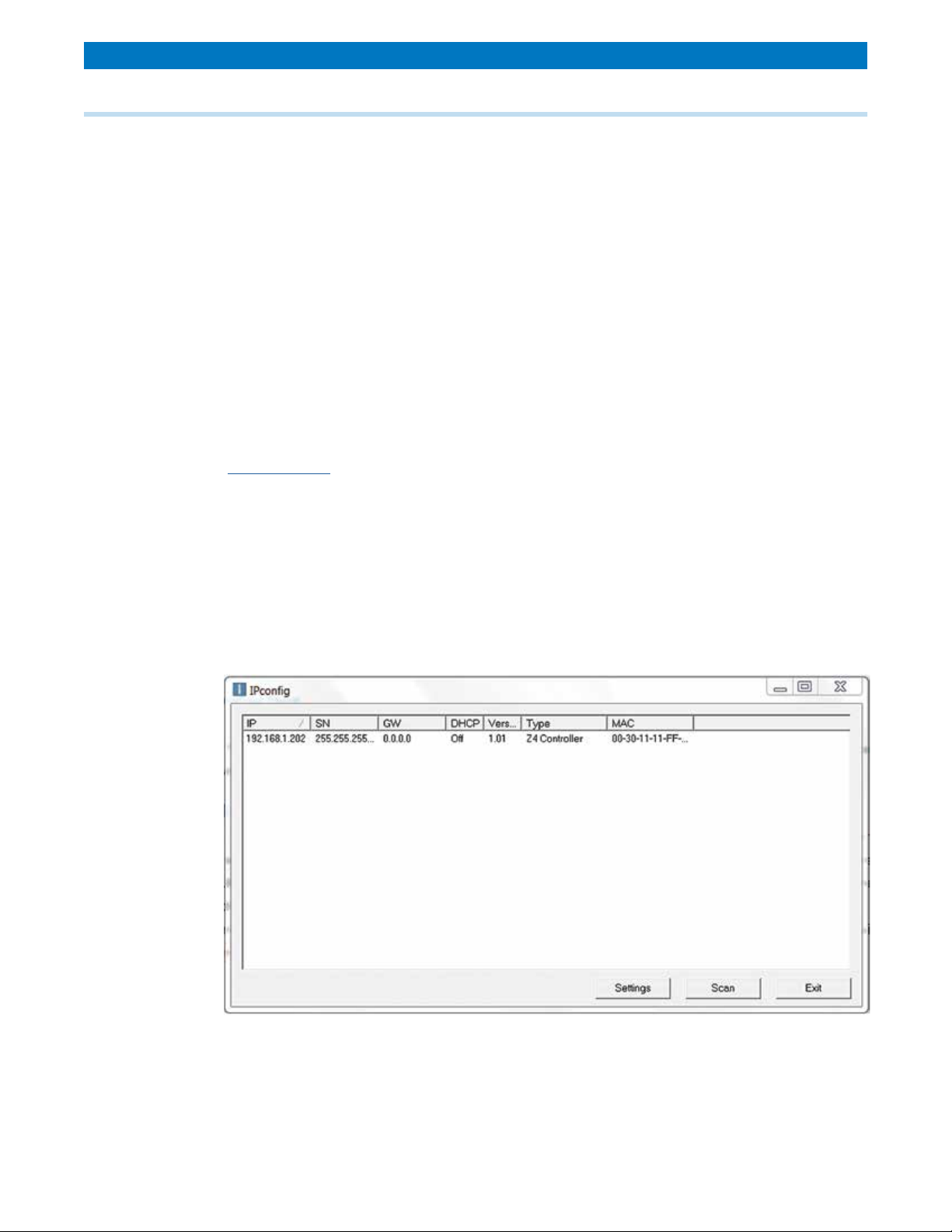
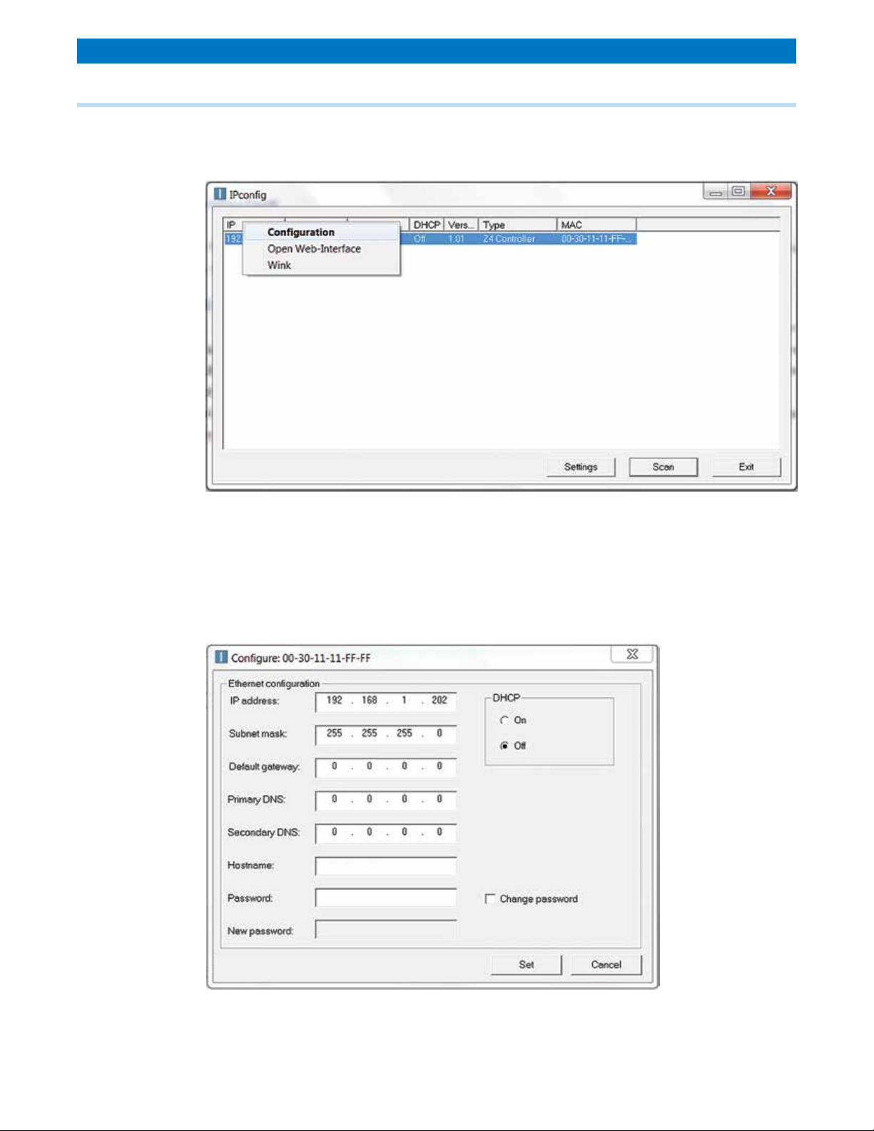
10.2 Ethernet (option)