2
[email protected] /
www
.montalvo.com
/
Technical details subject to change without notice. U4-technical manual-us © Montalvo General
1
●Universal 100-240VAC (Optional 24VDC).
●Display of all Information in either English or Metric units.
●Can be used with ultrasonic or laser diameter sensors, rider arms or proximity switches.
●Programmable Soft Start, Anti-coast, and Hold values allow precise control of starting and
stopping during quick Cycle applications.
●Two different alarm settings can be programmed to alert the operator or can be connected
to machine controls to slowdown and stop machine.
●Set up and programming can easily be done using the keypad and display or with free
software through the USB port.
●Stores and re-calls up to 9 sets of control parameters for different materials.
●Can be used with TS torque sensor to display actual calculated Web Tension.
1.1 Overview
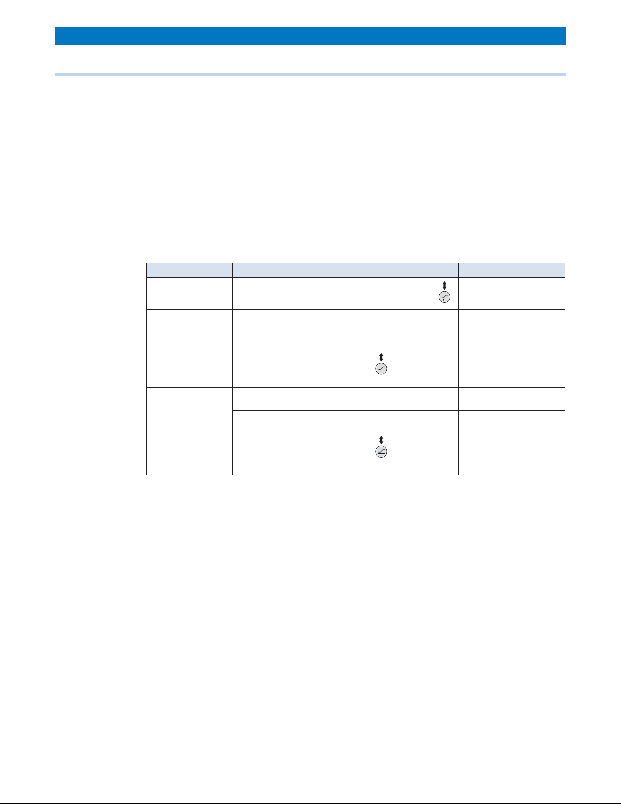
1.2 System Operation
In order to properly set up and program the U4, as well as take advantage of all the available
features, it is important to have a basic understanding of the controller and how it ts into the
tensioning system. Refer to the drawing below.
A typical pneumatic unwind system using an ultrasonic sensor is shown, however the same
principles apply to most open loop tension control systems. The calibrated sensor supplies the
correct diameter to the U4 which applies a proportional output to the brake. The operator sets
the desired amount of tension on the web by increasing or decreasing the trim value to add to
or subtract from the output proportional to the diameter. As the roll diameter decreases, the U4
reduces the output to the brake. Since the output to the brake is proportional to torque, and
since Tension is equal to the Torque divided by the radius, the Tension will automatically remain
the same throughout the roll.
Pneumatic Brake
or Clutch
I/P Converter
Y
Web Direction
Z
Unwind or Rewind
Y
Regulated Air
Air Supply
Z
Y
OUTPUT
U4
US4 Ultrasonic Sensor
INPUT
Z
1
2
3
4
5
6
7
8
9
10
11
12
13
14
15
16
17
18
19
20
G
24 VDC
-+
U4 Controller Rev #
© Montalvo
Serial #
00000
4
ontroller Rev #
TENSION ONAUTOSTOP
Controller
U4
OUTPUT
TRIM
DIAMETER
TAPERSTART
TAPER%
TENSION
INCREASE SCROLL
TENSION
ON / OFF
DECREASE AUTO / MAN
12345
000000
TYPE
www.montalvo.com
TensionControllers
SN PN
VOLTS AMPS
®
U4
MADEIN USA
207-856-2501 / 800-226-8710
+86-21-52188010
+45 75 57 27 11
+49 (0)511760 69141
IP54
CS100
CS130
V250
V300
V400
MPC4
US4
or
PS1
M4
Tension
Controller
Brake
Web
Unwind
I/P
Converter
Torque
Sensor
Ultrasonic or Proximity
Non-Contact Sensors
Tension
Meter
TS U4
Montalvo TSC™System
The Montalvo U4 Open Loop Controller provides
precise, accurate control of web tension by
varying torque based on diameter. The control
outputs of 0-10VDC and 4-20mA enable the
U4 to interface with a variety of torque
output devices to control web tensioning
brakes, clutches and motor Drives. The
TSC™ System utilizing a TS Torque Sensor adds
the ability to monitor actual web tension from full
roll to core. Standard U4 features include:
TS