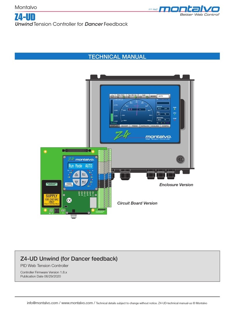
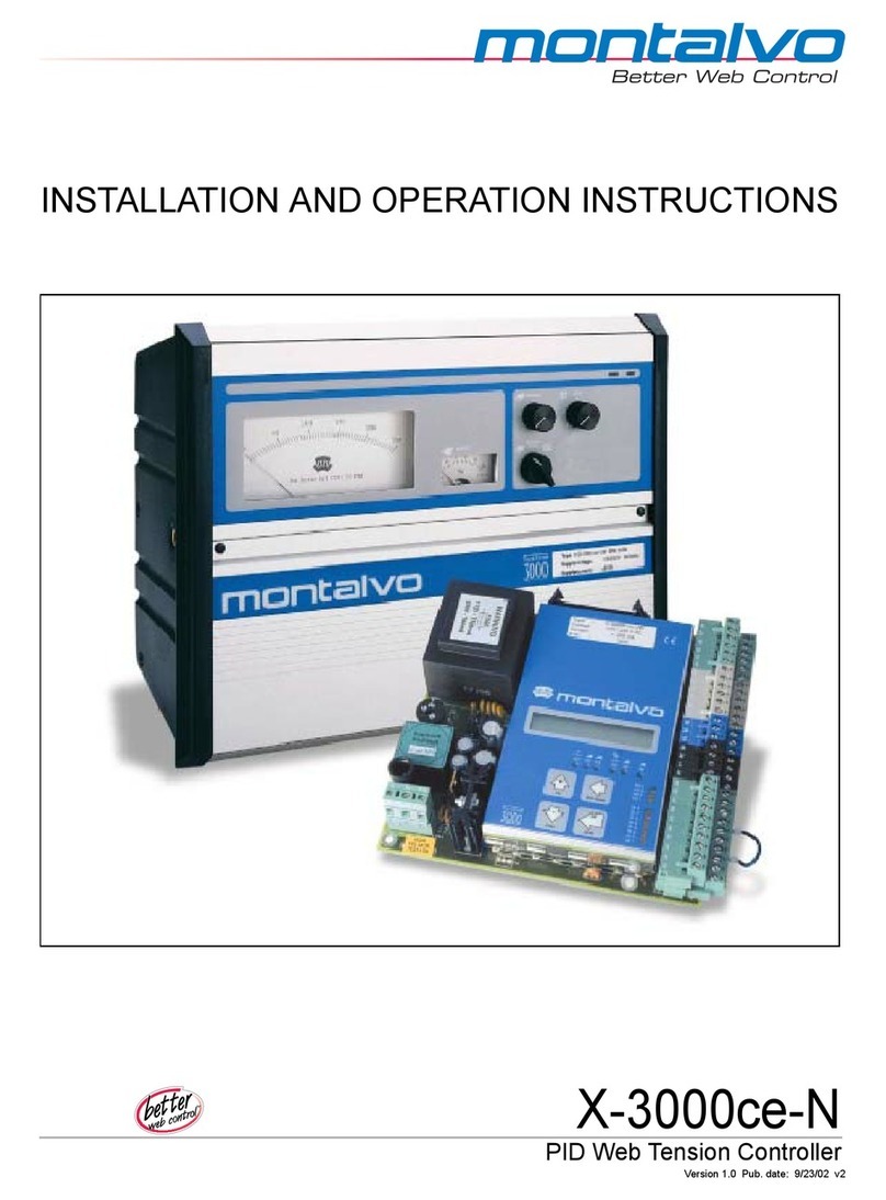
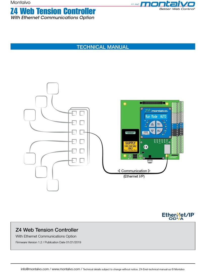
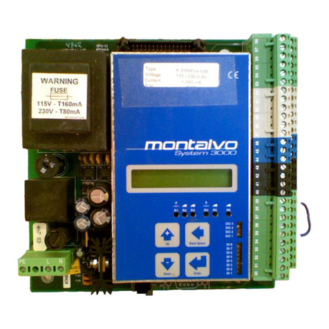
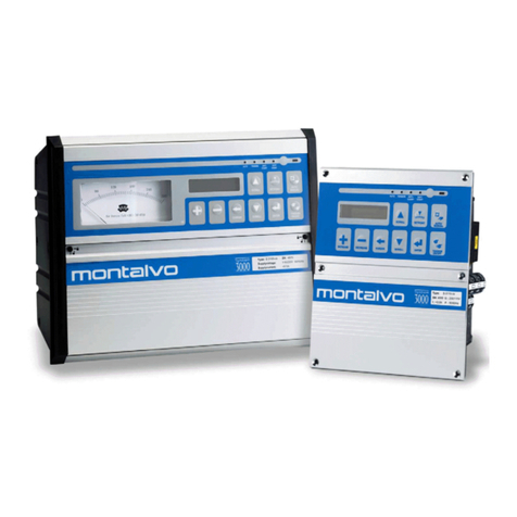
Montalvo X-3100ce-RW User manual

Better Web Control
INSTALLATION AND OPERATION INSTRUCTIONS
X-3100ce-RW
PID Web Tension Controller
Version 3.2 Pub. Date 10/6/03 v1


Table of Contents
3
1 GENERAL DESCRIPTION 5
2 TECHNICAL DATA 8
2.1 X-3100-CE ELECTRICAL 8
2.2 X-3000-CE MECHANICAL 9
2.3 RS-232 COMMUNICATIONS PACKAGE (OPTIONAL) 10
2.4 FIELDBUS COMMUNICATIONS PACKAGE (OPTIONAL) 11
3 INSTALLATION AND SETUP 12
3.1 MECHANICAL INSTALLATION 12
3.2 ELECTRICAL INSTALLATION 15
3.3 QUICK SETUP GUIDE 16
3.4 STARTUP AND ADJUSTMENT. 22
3.5 BASIC DIAGRAMS FOR STANDARD APPLICATION 24
3.6 TOTAL WIRING DIAGRAM 26
3.7 TERMINAL BLOCKS 28
3.8 BASIC WIRING INSTRUCTIONS 29
3.9 DIGITAL INPUT: STANDARD FUNCTIONS 32
3.10 ANALOG SIGNALS: STANDARD FUNCTIONS 38
3.11 INPUT AND OUTPUT: SPECIAL FUNCTIONS 39
3.12 WEB BREAK 40
3.13 TAPER 42
3.14 DIAMETER 44
3.15 OPERATION OF THE CONTROLLER MENU 48
3.16 MENU TREE DIAGNOSTIC 49
3.17 RUN MODE 49
3.18 MENU TREE 50
3.19 SETUP MENU 51
3.20 HARDWARE ADJUSTMENT AND LEDS52
4 CALIBRATION 53
4.1 TENSION ADJUSTMENT 53
4.2 REGULATOR MENU 54
4.3 TUNING 55
4.4 CUSTOMER PARAMETER SETTINGS 56
5 OPERATION 57
6 TROUBLESHOOTING 59


1. General Description
5
1 General Description
The Montalvo X-3100ce-RW PID analog controller provides precise
automatic control of web tension. The progressive PID regulator
automatically compensates for roll diameter. The controller is used in a
closed loop, of which the load cell, motor and motor regulator are a part.
To properly set up and operate the X-3100ce-RW and to take advantage of
all its available features, it is important to have a general understanding of
the controller and its place in the tensioning system (please refer to the
diagram on the following page). A typical rewinder system is displayed;
however, the same principles apply to any other closed-loop control
system. The control outputs of 4 to 20 mA and 0 to 10 volts DC enable the
X-3100ce-RW to interface with a variety of output devices to control web
tensioning brakes, clutches, and motors.
Load Cell Function
Two load cells (also called transducers) are normally used. The signals
from the loadcells are summed together to indicate total web tension across
the entire web. Each load cell contains two strain gauges connected in a
series. The two load cells are connected so that the four strain gauges form
a Wheatstone bridge configuration supplied with + 2.5 VDC. The web
tension transfers a force to the load cell roll, changing the resistance values
in the bridge. The resulting voltage change is amplified and calibrated to
display actual web tension.
Torque control
The X3110ce system is based on “torque” control. This is a regulation type
that is used for soft regulation and machines with a “long” ramp up and
down time.
Motor Function
The Rewinder shaft is driven directly by the rewinder motor. If a gearing is
used, the maximum gear ratio recommended is 1:10.
Motor controller
It is possible to use a “simple” motor controller for the rewind motor. This is
because that the X3110ce has many special features that are required for
the “perfect” rewinder system.
Line speed
The line speed can be used in different ways. For the simple rewinder the
line speed is connected directly into the motor controller. For the more
advanced system the line speed has to be connected to the X3110ce. The
X3110ce will then control the “speed” setpoint for the rewinder as well.
1. General Description
6
Auto Mode Function (Closed Loop)
The operator sets the desired tension with the auto setpoint potentiometer.
The controller compares actual tension to the auto setpoint, and adjusts
output until the actual tension and setpoint are equal. Because the web
itself is part of the feedback loop, the X-3100ce-RW can quickly
compensate for speed and diameter changes, and for other factors that
affect tension during the process.
Manual Mode Function (Open Loop)
The operator sets the desired brake pressure with the manual
potentiometer. The web tension is still measured and displayed on the
tension meter, but is not regulated in this mode. To maintain tension, the
operator must make constant adjustments.
X-3100ce-RW
Motor
controller
50
20 80
100%0
MANUAL
AU T O
TENSION
OFF/ON
AUTO
MANUAL
OUTPUT
50
20 80
100%0
Type: X310 0-ce -RW SN: xxxx
Suppl y vo l t ag e : 115/230V 60/50Hz
Suppl y cu r r en t : <0.5A
Linespeed
IL300-X310-RW3-US

1. General Description
7
General Function and Standard Operation
Cabinet version
OPTION:
-Cal. low/high
OUTPUT
50
20 80
100%0
50
20 80
100%0
MANU AL /
AUT O
TENSION
OFF/ON
AUTOMANU AL
50
20 80
100%0
567 8
12 3
4
IL308-X310-RW-US
1. Manual setpoint
Sets controller output at a constant level when the controller is in
manual mode. (Manual setpoint on a 0 to 100% scale produces 0 to
100% output.)
2. Auto setpoint
In auto mode, the controller automatically regulates output so that
actual tension reaches the tension setpoint (appears on a scale of 0
to 100% on the meter).
3. Green power LED Indicates that power is on.
4. Taper % Sets the % for the Taper reduction.
5. Actual tension Displays actual tension on a scale of 0 to 100%.
6. Controller output meter Displays controller/regulator output on a scale of 0 to 100%.
7. Manual / Auto switch Switches between manual and auto mode.
8. Tension on/off switch Turns tension on and off. Output is zero when off.

2.1 X-3000-ce Electrical
8
2 Technical Data
2.1 X-3100-ce Electrical
AC Input 115 or 230 VAC +10% (IEC TC77B WG3) 48 to 62 Hz
Fuse Size (fuse not installed by factory)
115 V-160 mA T (slow-blowing type) Ø5 x 20 mm
230 V-80 mA T (slow-blowing type) Ø5 x 20 mm
(Both types are supplied)
Overvoltage Category II (IEC 664)
2 kV in 1 minimum primary to secondary
Pollution Degree 2
Material Fire Classification 94V0
Maximum Power Consumption 12 VA
Maximum Fuse Input 10A
Noise Immunity EN 50082-2 industrial
Noise Emission EN 50081-1
Load Cell Supply ±2.5 VDC ±5%
Load Cell Input 0 to ±250m VDC
Zero Range (tare) 100% of load cell rating [max. 500mVDC (+/- 250 mVDC)]
Calibration Range Gain: 11 to 480
Temperature Range 0 to 50° C (32 to 122° F) operating
-10 to 80° C (14 to 176° F) storage
Degree of Protection IP 54 / IP 10 for non-cabinet version
Regulator Outputs
0 to 10 VDC
Maximum load - 5 mA
4 - 20 mA / 0-20 mA
RL = 0 to 1000Ω
Meter Outputs
0 to 100 µA
RO = 100 KΩ
0 to 10 VDC
Maximum load - 5 mA
Analog Input Voltage 0 to 10 VDC
RI = 100 KΩ
Digital Input Voltage 15 to 30 VDC
RI = 10KΩ
Digital Output Voltage
24 VDC ±15%
Imax for a digital output: 100mA
Total Imax for all 4 outputs: 250mA (if internal power supply is
used).
Standards Designed to meet UL 508 and EN 60204

2.2 X-3000-ce Mechanical
9
2.2 X-3000-ce Mechanical
Dimensions (L x W x H) (Cabinet version) 330 x 260 x 163 mm (12.99" x 10.23" x 6.43")
Weight (Cabinet version) 4.7 kgs (10.38 lbs.)
Dimensions L x W x H (non-cabinet version) 160 x 160 x 55 mm (6.3" x 6.3" x 2.36")
Weight (Non-cabinet version) 1 kg (2.2 lbs.)
Cabinet version
50
20 80
100%0
MANUAL
AU TO
TENSION
OFF/ON
AUTO
MANUAL
OUTPUT
50
20 80
100%0
Type: X3100-ce-RW SN:xxxx
Suppl y vol t ag e: 115/230V 60/50Hz
Supplycurrent: <0. 5A
IL220.dsf
Non-cabinet version
3031323334353637383940414243444546474849505152535455565758
R1 R2 R3 R4 R5 R6
Enter
+
Back Space
Down
Up
DO 4
DO 3
DO 2
DO 1
DI 8
DI 7
DI 6
DI 5
DI 4
DI 3
DI 2
DI 1
0
0
-
PE
230
115
Diagnostic
L N
Type : xxx3100Pce-RW
Voltage : 115 / 230 V AC
Current : <200 mA
S. nr. : 3000
1234567891011121314151617181920212223242526272829
123
4
5
6789
IL221.dsf

2.3 RS-232 Communications Package (Optional)
10
2.3 RS-232 Communications Package (Optional)
30 31 32 3334 35 36 37 38 3940 4 1 42 43 44 4546 47 48 49 50 51 5 2 53 5 4 55 5 6 57 58
R1 R2 R3 R4 R5 R6
Enter
+
BackSpace
Down
Up
DO4
DO3
DO2
DO1
DI8
DI7
DI6
DI5
DI4
DI3
DI2
DI1
0
0
-
PE
230
115
Diagn ost ic
L N
Type : xxx3100Pce-UW
Voltage : 115 / 230 V AC
Current : <200m A
S. nr. : 300 0
1 2 3 4 5 6 7 8 9 10 11 12 1 3 14 15 16 17 18 19 20 21 22 2324 25 26 27 28 29
12345
6789
50
20 80
100%0
MANUAL
AUTO
TE NSION
OF F /ON
AUTO
MANUAL
OUTPUT
50
20 80
100%0
Type:X3000- ce- U W SN:3455
Supplyvo ltage:11 5/2 30V 60/50Hz
Supplycu rrent: <0.5A
SPLICE
LOW/HI GH
IL211.dsf
PC xxx3100Pce-xx xxx3100ce-xx
RS-232
The System 3100ce has an optional RS-232 Communications for setting
up and viewing the status of parameters from a PC or laptop. All items
necessary for using RS-232 with the System 3100ce are included
with this package.
The RS-232 communications package contains:
1. CD-ROM (software and PDF manual)
2. RS-232 Cable (RJ-11 to D-SUB 9 pin [4 m /12 ft.])
3. User manual (in hard copy).
The software package features two modes of operation:
1. Parameter setup: set up and back up all parameters with a PC or
laptop.
2. Remote control: monitor the status of controller signals online.
Technical specifications for RS-232:
• RS-232: baud rate 4800-38400, 8 data bits, 1 stop bit and no parity
(default 9600)
• Remote setup: all parameters on the controller are available for remote
configuration.
• Remote monitor (status): for all digital and analog signals from the
controller.

2.4 Fieldbus Communications Package (Optional)
11
2.4 Fieldbus Communications Package (Optional)
FIELDBUS
50
2080
100%0
MANUAL
AUTO
TENSION
OFF/ON
AUTO
MANUAL
OUTPU T
50
2080
100%0
Type:X3000-ce-UW SN:3455
Supplyvoltage: 115/230 V 60/50Hz
Supplycurrent: <0.5A
SPLICE
LOW/HIGH
PLC xxx3100Pce-xx-XX xxx3100ce-xx-XX
IL2 12.ds f
3031 32 3334 35 36 37 38 39 40 4142 43 44 45 46 47 4849 50 5152 53 54 5556 57 58
R1 R2 R3 R4 R5 R6
Enter
+
BackSpace
Down
Up
DO 4
DO 3
DO 2
DO 1
DI 8
DI 7
DI 6
DI 5
DI 4
DI 3
DI 2
DI 1
0
0
-
PE
230
115
Diagnostic
L N
Type : xxx3100Pce-UW
Voltage : 115/ 230 VAC
Cur r en t : < 2 00 mA
S. nr. : 300 0
1 2 3 4 5 6 7 8 9 10
11 12 1 3 1415 16 17 18 19 20 21 22 23 24 2526 27 28 29
12345
6789
The 3110ce controllers can be delivered with a Fieldbus communication
package option. Controllers with this package are named as follows:
xxx3110ce-xx-PB (Profibus-DP)
xxx3110ce-xx-DN (DeviceNet)
Controllers with the Fieldbus option require the following:
• CD-ROM (GSD File (PB), EDS File (DN) and PDF Manual)
• User Manual (in hard copy)
Technical specifications for Fieldbus:
• Profibus: connection to the Profibus-DP with a D-SUB 9 pin.
Maximum 12 mbaud.
• DeviceNet: connection to DeviceNet with a terminal block with 5
Connections. Maximum 500Kbits/s.
• Remote monitor (status): all digital, analog, and internal signals
From the controller.
• Process control: all digital and analog signals can be controlled
From the master device (PLC).

3.1 Mechanical Installation
12
3 Installation and Setup
3.1 Mechanical Installation
PE L N
IL222.dsf
167 mm
169 mm
10 mm
3031323334353637383940414243444546474849505152535455565758
R1 R2 R3 R4 R5 R6
Enter
+
Back Space
Down
Up
DO 4
DO 3
DO 2
DO 1
DI 8
DI 7
DI 6
DI 5
DI 4
DI 3
DI 2
DI 1
0
0
-
PE
230
115
Tension 0%
L N
Type : X-3100Pce-RW
Voltage : 115 / 230 V AC
Current : <200 mA
S. nr. : 3000
148 mm
120 mm
1234567891011121314151617181920212223242526272829
12345
6789
55 mm

3.1 Mechanical Installation
13
Avoid mounting
the controller
cabinet close to
drive controllers
or any other
equipment that
produces large
amounts of EMI.
3.1.1 Cabinet
The controller cabinet should be mounted in a dry place, away from any
source of heat. The mounting surface should be free of any excessive
vibration. If possible, the controller should be mounted at eye level and in a
location accessible to the operator.
Enclosure with doors open
Note: Plastic latch to hold door open
18.00" (457)
8.25"
(
210
)
10.23"
(260)
11.81 (300)
12.99" (330)
6.43" (163) 0.39" (10)
Space for mounting
bracket
6.82" (173)
50
20 80
100%0
MANUAL
AUTO
TENSION
OF F/ ON
AUT O
MANUAL
OUT PUT
50
20 80
100%0
Typ e: X3100-ce- RW SN: xxxx
Supply volt age: 115/2 30V 60/50Hz
Supply current: <0.5A
IL223.dsf

3.1 Mechanical Installation
14
3.1.2 X-3000-ce-RW Cabinet
Figure 1 mount standard. For other mounting brackets, consult factory.
Fig. 1
18°
18°
Fig. 2
20°
45°
Fi
g
. 3 Fig. 4 IL037.dsf
Cutout dimensions: 320 x 250 mm

3.2 Electrical Installation
15
3.2 Electrical Installation
Warning: Electrical installation must be done by skilled personnel. Wiring
must meet all applicable codes and standards.
Refer to appropriate wiring and terminal descriptions for external
connections.
Be sure that the voltage selector on the regulator PCB is in the correct
position for the voltage supplied.
Select the PCB fuse size according to the input voltage selected. The
maximum external fuse on the input is 10 A.
Note: 0VDC and PE are internally connected.
Note: Double-check accuracy of all wiring connections before applying
power to the controller. Damage caused by improper wiring is not covered
under warranty.
EMC Requirements
Connect protective ground wire to terminal marked PE. Ground wires
should be as short as possible. Connect PE, mounting plate, and cabinet to
a common ground.
Use only shielded cable for all external connections. For analog signals,
terminate shield at controller end; for digital signals, terminate shield at both
ends. For cabinet versions, connect shield to the cabinet at the point where
the cable enters, whether to a buss bar or to the connector housing. Keep
the shield as short as possible (not to exceed 10 mm or 0.4 inches). For
best results, clamp the uninsulated shield directly to the buss bar with the
strain reliefs provided.
Keep signal cables away from supply cables or any wires that conduct high
current. For best noise immunity, run signal cables close to the machine
frame, mounting plates, or other grounded structures.
Safety Information
The following safety symbols appear in this manual.
Caution Electrical Hazard
Failure to follow
installation and setup
instructions in this manual
may result in equipment
damage or personal injury.
Failure to follow wiring
instructions in this
manual may result in
equipment damage,
personal injury, or death.

3.3 Quick Setup Guide
16
The Quick Setup
Guide is intended
to help get the
system up and
running in a short
period of time.
To maximize
system
performance,
please read the
entire manual.
3.3 Quick Setup Guide
3.3.1 Introduction
The controller system will typically include the following components:
• 1 X-3100-ce-RW
• 2 load cells
• 1 Motor controller
• 1 Rewinder motor
- Start Rewinder
- Start Machine
115/230 Vac
Power supply
Load Cell 1 Load Cell 2
Motor
Controller
50
20 80
100%0
MANUEL/
AUTO TENSION
OFF/ON
AUTOMA NUE L
OUTPUT
50
20 80
100%0
Type:X3000-ce-UW SN: 3455
Supplyvoltage: 115/230V 60/50Hz
Supplycurrent: <0.5A
TAPER
50
20 80
100%0
X-3100ce-RW
PR301-X310-RW3-US
- Line Speed
Note: If the system includes other equipment, please refer to the
appropriate sections of the manual.
3.3.2 Mechanical installation
1. Mechanical installation
Mount all components on the machine.

3.3 Quick Setup Guide
17
3.3.3 Electrical Installation
1. Connection of line speed
Connect the line speed signal from the machine to the motor controller.
Typical it has to be connected on the “speed” setpoint. Please refer to the
motor controller documentation. (See example below):
Line speed
0 - 10 VDC
Speed
loop
Current
loop
+10 VDC
Torque
Limit
Max.
M
Motor
Example on a typical motor controller
Torque Input
0 - 10 VDC
PR300-X310- RW3-US
2. Regulated output to motor controller
Connect the regulated output from the X-3100-ce to the rewinder motor
controller. The signal has to be connected the “torque input”. Please refer
to the motor controller documentation. (See example below):
15 16 17
0 V
4 -20 mA
0 -10 V
Cable from X3100ce
to motor controller
Regulated
output:
Motor
Controller
WD300-X310-RW3-US
3031323334353637383940414243444546474849505152535455565758
R1 R2 R3 R4 R5 R6
Ent er
+
Bac k Sp ac e
Down
Up
DO 4
DO 3
DO 2
DO 1
DI 8
DI 7
DI 6
DI 5
DI 4
DI 3
DI 2
DI 1
0
0
-
PE
230
115
Diagnostic
L N
Type : xxx3100Pce-xx
Voltage : 115 / 230 V AC
Current : <200mA
S. nr. : 3000
1234567891011121314151617181920212223242526272829
12345
6789
Speed
loop
Current
loop
+10 VDC
Torque
Limit
Max.
M
Motor

3.3 Quick Setup Guide
18
3. Load Cells
Plug cables into load cells and connect cables to controller (see diagram
below).
LOAD CELL 1
CABLE
0VDC
+2.5V
-2.5V
-INPUT
*RED
*WHITE
*BLACK
LOAD CELL 2
CABLE
0VDC
-2.5V
+2.5V
+INPUT
Connection for T-Series
40414243444546
11121314151617
*RED
*WHITE
*BLACK
*Colors refer to standard cables supplied by Montalvo
1 2 3 4 5 6 7 8 9 10 11 12 13 14 15 16 17 18 19 20 2122 2324 25 26 27 28 29
30 31 32 33 34 35 3637 38 39 40 4142 43 44 45 46 47 48 49 50 5152 53 54 5 556 57 58
R1 R2 R3 R4 R5 R6
Ente r
-
+
Back Sp a c e
Down
Up
DO4
DO3
DO2
DO1
DI 8
DI 7
DI 6
DI 5
DI 4
DI 3
DI 2
DI 1
0
0
PE
230
115
TENSION 0%
L N
Ty pe : X-3 10 0c e-R W
Vol t age : 11 5 / 2 30 V AC
Current : <200 mA
S.nr. : 3000
WD301-XDTI310-ALL-US
4. Connection of Rewinder and Machine Start signals :
Connect cable from controller to the rewinder and the main panel. Connect
the signals as decribed in the following.
4.1 Start Rewinder (terminal 34):
Connect to a relay that:
• energize when the rewind motor starts running or moving
• de-energize when the rewind motor stops.
Note: From this relay use the closing function (NO). The relay function
must be closed at start and must open at stop (see diagram below)
4.2 Start Machine (terminal 6):
Connect to a relay that:
• energize when the main machine starts running or moving
• de-energize when stop is pressed or:
• when machine comes to complete stop (Zero speed signal).
Note: From this relay use the closing function (NO). The relay function
must be closed at start and must open at stop (see diagram below)
DI5Start Rew. /
1 2 3 4 5 6 7 8 9 10
30 31 32 33 34 35 36 37 38 39
11 (COM)
WD302-X310-RW23-US
Start Machine
/ DI8
START
Machine
K110
K110
K100
13 (NO)
START
MACHINE
Machine
STOP
11 (COM)
START
Rewinder
K100
K100
13 (NO)
START
REWINDER
R
ewinder
STOP
+24VDC

3.3 Quick Setup Guide
19
5. Connection of supply voltage to the controller.
Connect cable between machine main panel and the controller.
Select a supply voltage (230/115 VAC) that is turned on when the power to
the machine main panel is turned on. Then:
a) Turn off machine main panel.
b) Connect cable in the machine main panel.
c) Remove fuse from the fuse holder on the printed circuit board (PCB)
if fuse is already installed.
d) Connect cable in the the controller (see diagram below)
30 31 32 33 34 35 36 37 38 39 40 41 42 43 44 45 46 4 7 48 49 50 51 52 53 54 55 56 5 7 58
R1 R2 R3 R4 R5 R6
Ent er
+
Back Space
Down
Up
DO 4
DO 3
DO 2
DO 1
DI 8
DI 7
DI 6
DI 5
DI 4
DI 3
DI 2
DI 1
0
0
-
PE
230
115
Diagnostic
L N
Type : xxx3100Pce-UW
Voltage : 115 / 230 V AC
Current : <200 mA
S. nr. : 3000
1 2 3 4 5 6 7 8 9 1 0 11 12 13 14 15 16 1 7 18 19 20 21 22 23 24 25 26 27 28 29
12345
6789
L N PE
220
230
115
Max.
10mm
Voltage Switch ( In 230 v Position )
Fuse Holder
FUSE SIZE:
115V -160mA T (slow blowing type) Dia. 5 - 20 mm
230V - 80 mA T (slow blowing type) Dia. 5- 20 mm
PE L N
WD018.dsf
e) Turn on machine main panel again.
f) Using voltmeter, check connection of terminal points L, N and PE
before inserting fuse.
g) Turn machine off.
h) Insert correct fuse and turn machine on.

3.3 Quick Setup Guide
20
For cabinet and
noncabinet
versions of the
controller, see
section 2.2, p. 7.
3.3.4 Tension Adjustment
1. Check that load cells are mounted and oriented properly. Refer to
the load cell installation instructions.
2. Before applying power, check that tension meter is mechanically
zeroed. If not, adjust the small screw below the meter scale until the
meter reads zero.
MANUAL
MANUAL/
AUTO
AUTO
TEN SION
OFF / ON
LOW /
HIGH
TAPER
20 80
50
20 80
50
20 80
50
OUTPU T
IL004.dsf
3. Apply power to the controller and let it warm up for at least 10
minutes.
4. With web removed and no tension applied to the sensing roller,
adjust potentiometer R1 until analog tension meter reads zero. (If
non-cabinet version is used, see digital display: tension should read
0%.) If value is below zero, turn R1 clockwise; if above, turn
counterclockwise.
R1 R2 R3 R4 R5 R6
+
Ba ck Spa ceUp
DO 4
DO 3
DO 2
DO 1
0
0
Load cell
IL005.dsf
Note: R1 and R2 are 25-turn potentiometers, so many rotations may be
required.
5. Thread a rope over the center of the tension-sensing roller following
the exact path of the web. Make sure the rope extends at least one
roller before and one roller after the sensing roller. Make sure the
rope does not pass over any dead bars or non-freewheeling rollers.
Fasten one end of the rope securely.
6. Attach a weight of known value to the other end of the rope. For
best results, the weight should be at least 25% of the analog
meter's full-scale value. A tension value below 0% with the weight
hung indicates that the signal from the load cells is reversed. In the
event of such a reversal, switch wires 12 & 14 and 41 & 43 on the
terminal block. To eliminate friction, rotate rollers in the direction of
the weight.
Table of contents
Other Montalvo Controllers manuals

Montalvo
Montalvo X-3000-ce-RW User manual

Montalvo
Montalvo Z4-UL User manual

Montalvo
Montalvo Z4 User manual

Montalvo
Montalvo Z4-UD User manual

Montalvo
Montalvo S3100 Service manual

Montalvo
Montalvo Z4 User manual

Montalvo
Montalvo X-3000ce-N User manual

Montalvo
Montalvo S4 Owner's manual

Montalvo
Montalvo U4 User manual
Popular Controllers manuals by other brands

Omron
Omron SYSMAC CV500 Operation manual

Dove Lighting Systems
Dove Lighting Systems SceneMaster 8 user manual

Flycolor
Flycolor Raptor S-Tower F4-20A user manual

Array electronic
Array electronic FAB2 Series user manual

THORLABS
THORLABS LDC 500 instruction manual

Micronor
Micronor MR380-1 Series instruction manual