Montalvo S4 Owner's manual

EST.
1947
TECHNICAL MANUAL
Technical details subject to change without notice. S4-technical manual-us © Montalvo
Montalvo
S4
Digital Tension Controller
S4 Digital Tension Controller
Installation and Operation
Pub. Date 12/17/2019

Montalvo
S-4
Digital Tension controller
p.2
[email protected] / www.montalvo.com / Technical details subject to change without notice. S4-technical manual-us © Montalvo
TECHNICAL MANUAL
1 General Description ...................................................................................................................... 3
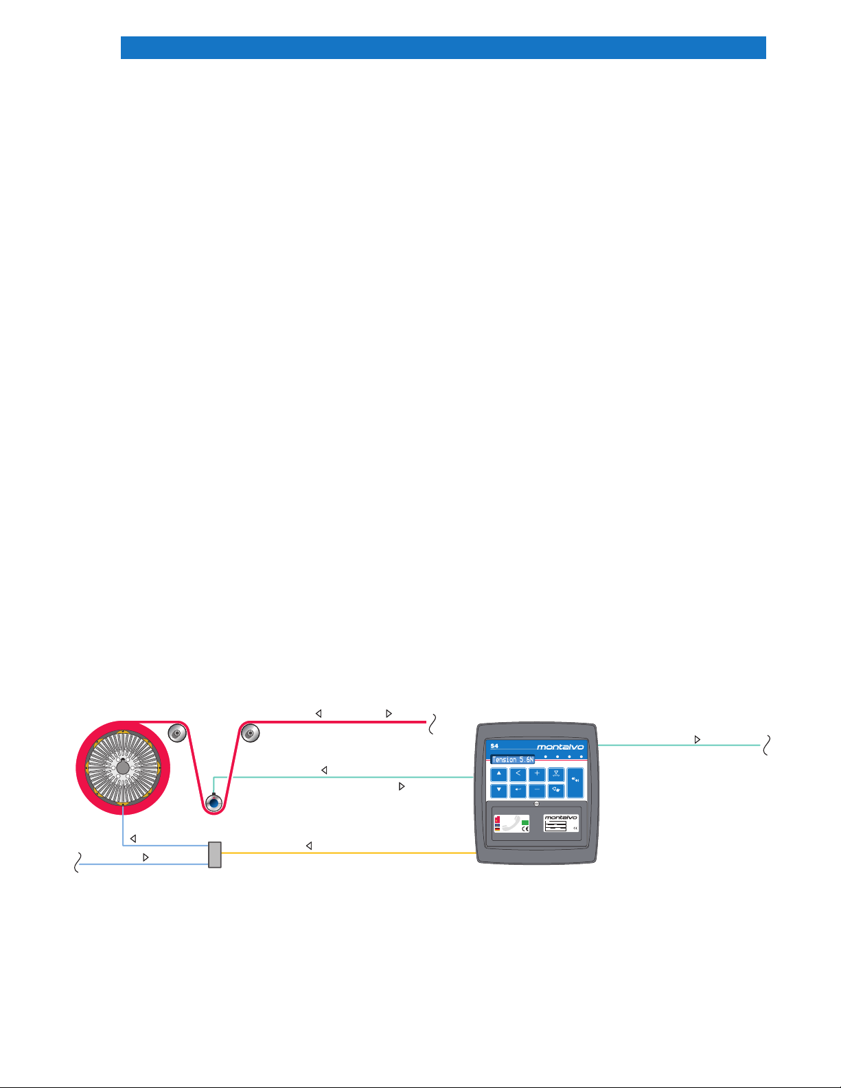
2 System Operation........................................................................................................................... 3
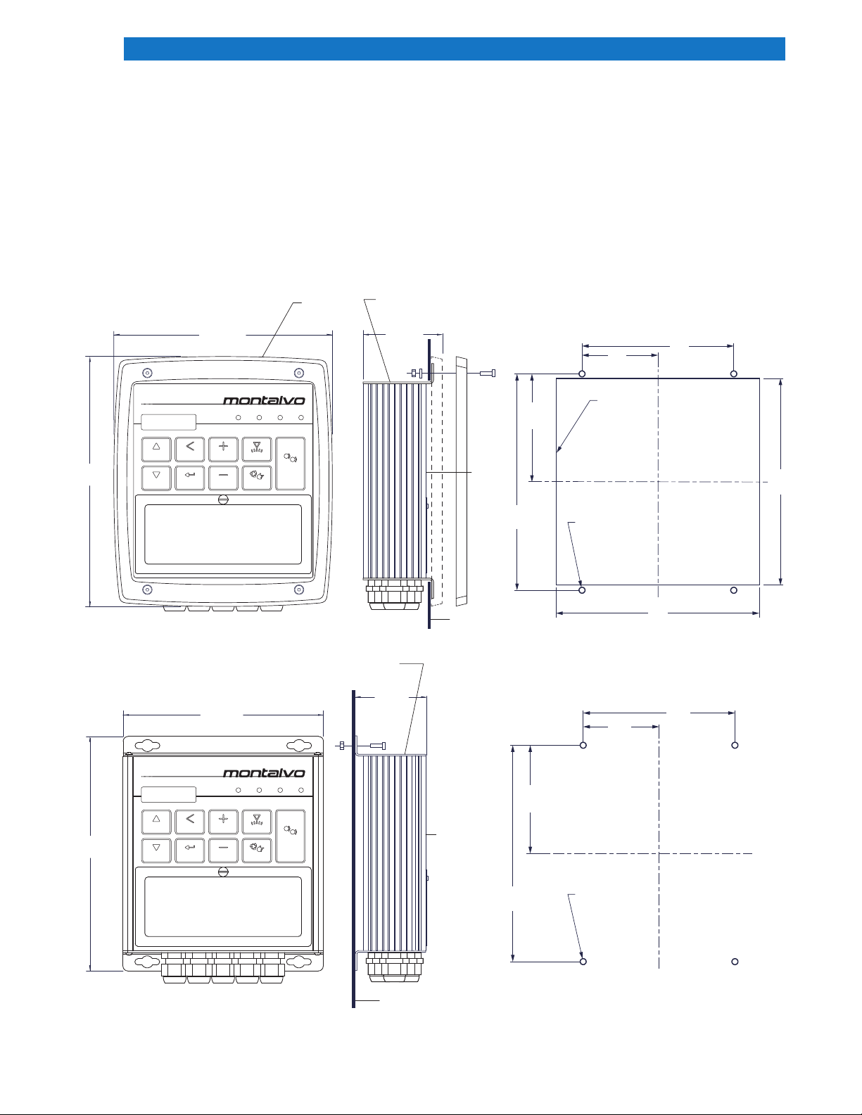
3 Installation ........................................................................................................................................... 4
3.1 Flush Mount ........................................................................................................................................... 4
3.2 Surface Mount........................................................................................................................................ 4
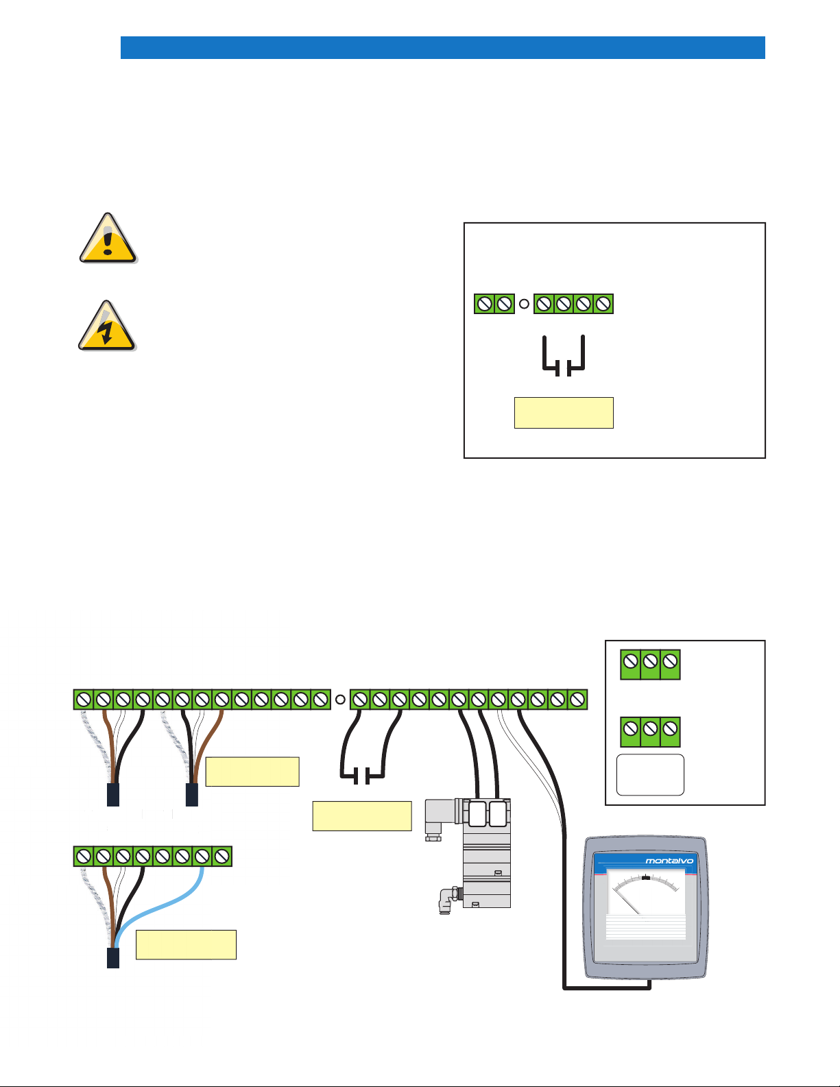
4 Electrical Connections ................................................................................................................ 5
5 Description of Adjustments ..................................................................................................... 6
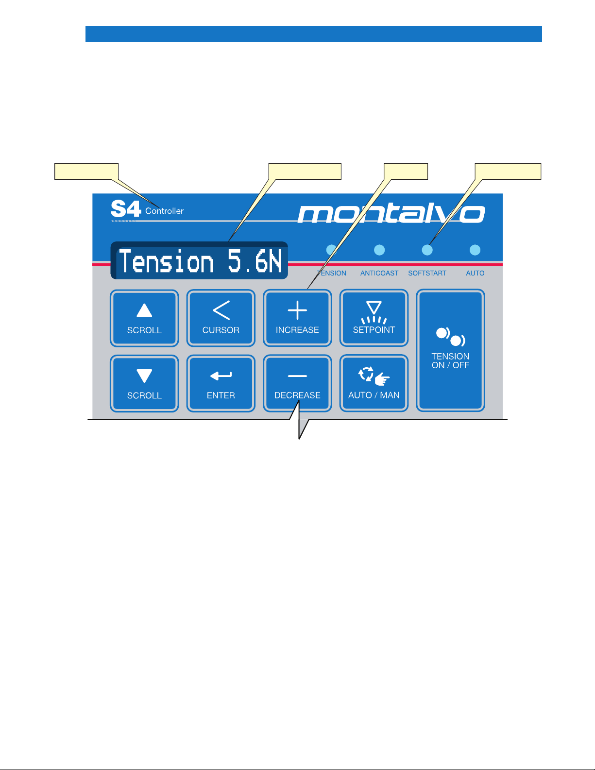
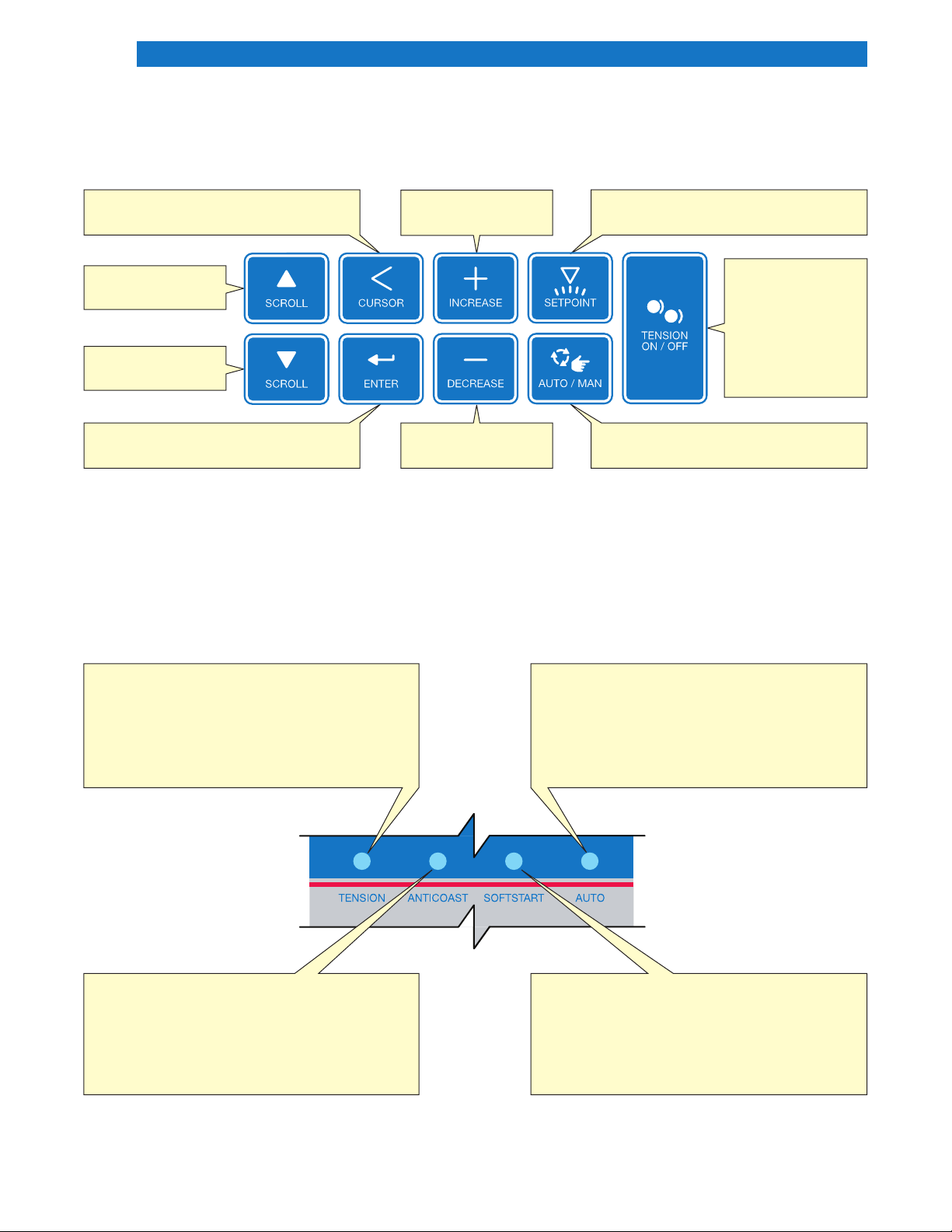
6 Description of Front Panel Display ..................................................................................... 7
6.1 Keypad................................................................................................................................................... 8
6.2 Status Indicator Lights............................................................................................................................ 8
7 Standard Pneumatic Setup...................................................................................................... 9
8 Calibration ......................................................................................................................................... 10
9 Standard Unwind Features..................................................................................................... 11
9.1 Soft Start.............................................................................................................................................. 11
9.2 Anti-Coast ............................................................................................................................................ 12
9.3 Splice ................................................................................................................................................... 12
10 Tuning the S4................................................................................................................................... 13
11 Standard Rewind Features..................................................................................................... 14
11.1 Inertia Compensation (see also Section 13.3 p.23 for more information) ............................................. 14
11.2 Taper Tension ..................................................................................................................................... 15
12 System Setup Menu Options................................................................................................ 16
12.1 Access to Menu........................................................................................................................................ 16
12.2 New Roll Default ................................................................................................................................. 16
12.3 Out Scale ........................................................................................................................................... 16
12.4 Meter Dampening............................................................................................................................... 16
12.5 Tension Display: Total or PLI ............................................................................................................... 16
12.6 Set Units............................................................................................................................................. 17
12.7 Web Break ......................................................................................................................................... 17
12.8 Remote Setpoint ................................................................................................................................ 18
13 Appendix ............................................................................................................................................ 19
13.1 Unwind Message Map........................................................................................................................ 19
13.2 System Setup Menu ........................................................................................................................... 21
13.3 Rewind Message Map ........................................................................................................................ 22
13.3.1 Rewind and Inertia Compensation ................................................................................................... 24
13.4 Parameter Settings............................................................................................................................. 25
13.5 Jumper Re-Conguration.................................................................................................................... 26
Table of Contents

Montalvo
S-4
Digital Tension controller
p.3
[email protected] / www.montalvo.com / Technical details subject to change without notice. S4-technical manual-us © Montalvo
TECHNICAL MANUAL
1 General Description
The Montalvo S4 Digital Controller provides precise, accurate control of web tension. The control outputs of 0-10VDC
and 4-20mA enable the S4 to interface with a variety of torque output devices to control web tensioning brakes,
clutches and motors. Standard features of the S4 include:
1. Supply voltages: Standard 100 - 240VAC, 50/60 Hz. Optional 24VDC version.
2. Push Button Calibration and Tuning.
3. Display of all Key Settings in either English or Metric Units.
4. Proprietary “Diamatic” control algorithm which provides uniform control response regardless of roll diameter.
5. Programmable Soft Start, Anti-coast, and Splice features.
6. Stores and re-calls up to 12 sets of control parameters for different materials.
2 System Operation
In order to properly set up and program the S4, as well as take advantage of all the available features, it is important
to have a basic understanding of the controller and how it ts into the tensioning system. Please refer to the
drawing below.
A typical pneumatic unwind system is shown, however the same principles apply to most closed loop tension control
systems. The operator sets the desired tension using the S4 Keypad. The load cells produce a voltage signal that is
proportional to the web tension.
This signal, which has been calibrated to reect the actual web tension, is compared to the desired tension, and the
S4 automatically adjusts the air pressure to the brake to make the actual tension the same as the desired tension.
Since the web itself is part of the feedback loop, the S4 can quickly compensate for speed and roll diameter changes
as well as other factors that may affect tension during the unwinding or rewinding process.
Regulated Air
Electrical Supply
Air Supply
OUTPUT (electrical signal)
OUTPUT
(electrical signal)
Brake
or Clutch
I/P Converter
Load Cell
INPUT (electrical signal)
Web DirectionUnwind or Rewind
TENSION ANTICOAST SOFTSTART AUTO
Controller
SCROLL CURSOR INCREASE SETPOINT
TENSION
ON / OFF
SCROLL ENTER DECREASE AUTO / MAN
S4
TYPE
www.montalvo.com
Tension Controllers
SN PN
VOLTS AMPS
®
MADE IN USA
S4 w/Enclosure
308255
100/240 0.12
11000608
207-856-2501 / 800-226-8710
+86-21-52188010
+45 75 57 27 11
+49 (0)511 760 691 41
IP54

Montalvo
S-4
Digital Tension controller
p.4
[email protected] / www.montalvo.com / Technical details subject to change without notice. S4-technical manual-us © Montalvo
TECHNICAL MANUAL
8.33
(212)
7.14 (182) 2.46 (63)
Trim Ring
7.61
(194)
6.50 (165)
2.29 (60)
End caps in
SURFACE MOUNT
position
Customer
Supplied
Fasteners
Montalvo
Supplied
Fasteners
End caps in
FLUSH MOUNT
position
Front of
Controller
Front of
Controller
Mounting
Surface
Mounting
Surface
6.70
170.2
6.60
167.6
4.92
125
7.02
178.2
3.51
89.1 TYP
2.46
62.6 TYP
Cut Out
3/16 (5) Recommended
4 places
3/16 (5) Recommended
Mounting Hole
4 places
4.92
125
7.02
178.2
3.51
89.1
TYP
2.46
62.6 TYP
Controller
S4
TENSION ANTICOAST SOFTSTART AUTO
SCROLL CURSOR INCREASE SETPOINT
TENSION
ON / OFF
SCROLL ENTER DECREASE AUTO / MAN
Controller
S4
TENSION ANTICOAST SOFTSTART AUTO
SCROLL CURSOR INCREASE SETPOINT
TENSION
ON / OFF
SCROLL ENTER DECREASE AUTO / MAN
3 Installation
Mount the S4 to a surface that is free from excessive heat and vibration. Locate where the keypad and display are
visible and easily accessible by the operator. If used for a pneumatic application, mount the MPC-4 as close to the
brake or clutch as possible. Make sure that the supply air is ltered and dry. It is recommended that you use a
Montalvo MAF-3 lter assembly. Failure to provide clean, dry air will degrade the performance and shorten the service
life of the MPC-4.
3.1 Flush Mount
3.2 Surface Mount

Montalvo
S-4
Digital Tension controller
p.5
[email protected]om / www.montalvo.com / Technical details subject to change without notice. S4-technical manual-us © Montalvo
TECHNICAL MANUAL
4 Electrical Connections
All electrical connections should be made by a qualied
technician and in accordance with all local codes and
ordinances. Refer to the wiring diagram below for all
necessary basic connections. Verify the accuracy of all
wiring connections before applying power.
SAFETY INFORMATION
The following safety symbols appear in this manual.
Caution
Failure to follow installation and setup
instructions in this manual may result in
equipment damage or personal injury.
Electrical Hazard
Failure to follow wiring instructions in this
manual may result in equipment damage,
personal injury, or death.
12 13 14 15 16 17 18
Start/Stop
contact shown in
Run Mode
DRY CONTACT ONLY
Start/Stop
Gnd
IMPORTANT!
Make sure to install a Start/Stop Contact. The S4
will not operate properly without it.
Install ontact
on terminals:
#15 and #17
Montalvo offers
contact packages*:
#11001310 (120VAC)
#11001311 (24VDC)
* Packages include cable, relay and relay socket.
22 23
Shield
-Excitation (*Brown or *Red)
-Signal (White)
+Excitation (Black)
Shield
-Excitation (Black)
+Signal (White) (Blue for full bridge)
+Excitation (*Brown or *Red)
Gnd
Remote Setpoint (0-10VDC Input)
+10 VDC
Gnd
Splice
DO NOT USE
Start/Stop
Web Break
Gnd
Remote Tension Off
0-10VDC Output
Gnd
4-20mA Output
Tension Output (0-10VDC)
Gnd
24VDC Output
Gnd
24 VDC Input
123456789101112131415161718192021 242526
GN
24VDC
L
G-+
AC Input
120-240 VAC
50/60 Hz
DC Input
24 VAC
*
Load Cell
#1
*
Load Cell
#2
Montalvo MPC-4
I/P Converter
Start/Stop
contact shown in
Run Mode
DRY CONTACT ONLY
Power Supply Options
The S4 is available as either
an AC or DC version.
**
inf
o@
m
o
nt
a
lv
o
.
co
*
Load
C
el
l
#1
*
Load
Ce
#2
12345678
*From 4 pin connector - BROWN wire (shown) - From 3 or 6 pin connector RED wire
0
10
20
30 40 50 60 70
80
90
100
M4
Meter
21
-
+
Montalvo M4
Tension Meter
Two Half Bridge
Load Cells
Single Full Bridge
Load Cell
www.montalvo.com

Montalvo
S-4
Digital Tension controller
p.6
[email protected] / www.montalvo.com / Technical details subject to change without notice. S4-technical manual-us © Montalvo
TECHNICAL MANUAL
5 Description of Adjustments
LC ZERO – Coarse zero adjustment of the load cell input. Necessary to offset the effects of heavy load cell rollers.
The nal adjustment will be made in the software. Note: 25 turn potentiometer.
RMSP ZERO – Optional Feature – See adjustment procedure in Appendix.
SW-1 – Supervisor – Operator Switch – Slide the switch to the left in order to access standard setup menus and
utilize optional features. After setting up the S4, slide the switch to the right to provide the operator with a minimum
number of messages for ease of operation.
CONTRAST – Adjusts the alphanumeric display for optimum viewing once the controller is mounted.
Note: Single turn Potentiometer.
OUT ZERO – This is factory set to insure the regulated outputs on terminal 19 is 0VDC and Terminal 21 is 4mA.
DO NOT ADJUST.
LC ZERO RMSP ZERO SW-1 OUT ZEROCONTRAST
Supervisor - Operator
ÍÎ
1234567891011121314151617181920212223242526

Montalvo
S-4
Digital Tension controller
p.7
[email protected] / www.montalvo.com / Technical details subject to change without notice. S4-technical manual-us © Montalvo
TECHNICAL MANUAL
6 Description of Front Panel Display
Help Button KeypadDigital Display Status LEDs

Montalvo
S-4
Digital Tension controller
p.8
[email protected] / www.montalvo.com / Technical details subject to change without notice. S4-technical manual-us © Montalvo
TECHNICAL MANUAL
6.2 Status Indicator Lights
6.1 Keypad
The following diagram shows the keypad with a brief explanation of the functions of the keys.
*The cursor is a line underneath a digit in the display, marking the position of the character that can be edited or
entered.
If the cursor appears, each time the cursor key is pressed, the cursor moves one position to the left. When it has
gone as far left as possible for the particular message, it will return to the least signicant digit. If the cursor is not
showing on a message that can be edited, pressing the cursor key will make it appear.
Toggles between
tension on and
tension off. When
off, no air is
applied to brake.
When on, Tension
LED is lit.
Scrolls to sertpoint message so Auto
Tension can be changed.
Places cursor*under digit to be
changed.
Toggles berween auto & manual. When
in auto, Auto or Softstart LED is lit.
Enters displayed value into memory. Decreases value of
digit above cursor.
Increases value of
digit above cursor.
Scrolls up list of
messages.
Scrolls down list of
messages.
AUTO - Indicates that controller is in automatic
mode. Controller will adjust output as needed to
maintain setpoint value. To change tension in
auto mode, change setpoint. The auto light
should only be on when the machine is running.
TENSION ON/OFF - Indicates that an output is
being applied to brake. If only tension light is
on, the controller is in manual mode. In manual
mode, a change in output changes tension.
Pressing Tension On/Off key turns tension on
and off.
ANTICOAST - Indicates that controller is in the
anticoast mode. Should only light up when stop
button on machine is pushed and should
remain on until machine has come to a
complete stop.
SOFTSTART - Indicates that controller is in
softstart mode. Should only be on when
machine has stopped. When run button on
machine is pushed, this light will blink for a set
time, then go out, and auto light will come on.

Montalvo
S-4
Digital Tension controller
p.9
[email protected] / www.montalvo.com / Technical details subject to change without notice. S4-technical manual-us © Montalvo
TECHNICAL MANUAL
Initial Settings
In order to keep the set-up time of the S4 to an absolute minimum, as many parameters as possible are factory set
for the majority of applications. The following procedure will allow you review these settings and change them if it is
necessary.
Step 1: Apply power to the S4 and let it warm up for at least 10 minutes. The front panel LEDs will
illuminate in a sequential test pattern and the display will read initializing... You will then see the
Montalvo copyright message scroll across the display screen. Adjust the display for easy reading by
turning the Contrast potentiometer using a small screw driver (see p. 5 for potentiometer location).
Step 2: Insure that SW1, the supervisor slide switch is slid to the “Left” position.
Step 3: If it is not already displayed, scroll down until WebLine is displayed. Use the “Enter” key to select
Unwind for brake applications or Rewind for clutch applications. Scroll down once.
Step 4: MeterScale is now displayed. If you are utilizing the optional M4 Analog meter, this value should
agree with the full scale value of the meter. If it does not, change the appropriate digit(s). Press
“Enter” to store the data. If you are not using an analog meter, set this value to a value equal to two
times the maximum tension you expect to run. Scroll down.
Step 5: OutLimit is now displayed. If it is not already set to 75 PSI, change the appropriate digit(s). Press
the “Enter” key to store the data. The display scrolls down automatically. The message Tenszero
will be displayed. Proceed to the calibration section below.
7 Standard Pneumatic Setup

Montalvo
S-4
Digital Tension controller
p.10
[email protected] / www.montalvo.com / Technical details subject to change without notice. S4-technical manual-us © Montalvo
TECHNICAL MANUAL
The following procedure must be performed to enable the S4 to accurately measure, display and control tension.
Step 1: Scroll to the TensZero message. With web removed, adjust the LC ZERO potentiometer for a zero
reading . Note: This potentiometer is a 25 turn potentiometer, so many rotations may be required.
Scroll down once.
Step 2: TensCalibrate… is now displayed. Press the “Enter” key and C>Remover Web will be displayed.
When web is removed, press “Enter” again. After the Please Wait… message counts down, you will
be asked to press “Enter” again. C>PlaceCalWgt will be displayed. Do not press enter again until
you have completed Step 4.
Step 3: Refer to the diagram below. Thread a length of rope over the center of the tension roll following the
exact path of the web. Be sure that the rope extends at least one roll before and one roll after the
sensing roll. Make sure that the rope does not pass over any non-freewheeling roll. Fasten one end
of the rope securely.
Step4: Attach a weight of known value to the other end of the rope. For best results, the weight should be
at least 10% of the load cell load rating. Rotate all the rolls that the rope passes over in the direction
of the weight.
Step 5: Press “Enter” and C>CalWgt will be displayed. Set the digits equal to the weight that you are using.
Now press the “Enter” button and C>PleaseWait will be displayed. After the countdown, you will be
asked to
C>Press ENTER. After pressing the “Enter” button, C>Calibrated! will be displayed ,
indicating that the S4 is calibrated. If you have the optional M4, the analog meter will display the
correct reading. If you receive a message that reads cells reversed! , check to make sure that the
Load Cell are wired properly and that they are oriented correctly. The controller will have
automatically scrolled back to the TensZero message. If you receive a message that reads
WgtTooSmall!, check the Load Cell orientation and insure that the rope is threaded the same way
as the web. If everything is correct, increase the weight.
8 Calibration
Known
Weight
Rope fastened
to this roller
Load Cell
Roller

Montalvo
S-4
Digital Tension controller
p.11
[email protected] / www.montalvo.com / Technical details subject to change without notice. S4-technical manual-us © Montalvo
TECHNICAL MANUAL
9.1 Soft Start
Soft Start- why is it needed?
On a typical unwind application; it is often necessary to stop the machine during the run or to change rolls. Usually,
the web will relax slightly or go completely slack. The load cells will detect this and the control will start to increase the
air pressure to the brake. Because the machine is not running, the tension does not increase. The controller
continues to increase the air pressure to maximum. When the machine is restarted, the brake is completely locked
up. This usually results in a stretched or broken web. It is therefore desirable to take the controller out of the
automatic (closed loop) mode whenever the machine is stopped. Of course, the operator can perform this function
by simply putting the controller in manual when the line stops and switching it back into automatic once the line has
started. The disadvantage of this simple approach is the need for operator intervention whenever the line is stopped
or started. This can be avoided by implementing the soft start feature.
Soft start Implementation
In order to implement the soft start feature, you will need to supply the S4 with a dry, voltage free, external start/stop
contact which is isolated from ground and is open when the line is started and closes when the line is stopped. If the
anti-coast feature, which uses the same contact, is to be implemented the contact must close as soon as the line
starts to slow down prior to stopping. If anti-coast is not required the contact can close either when the line stops
(zero speed) or a xed time interval after the line stops. The contact should not open when the line is being jogged.
The opening of this contact turns tension on (if it is not already on) and sets the output (set by the NRollOut if the
tension has been turned on and off, or the calculated soft frac value) for an adjustable period (set by SoftTime).
During this time, the soft start LED will blink. The S4 then switches into the automatic mode, the soft start LE turns off
and the auto LED turns on. After the machine has run for approximately 2 seconds the S4 begins to put in memory
the output going to brake.
When the stop/start contact closes, the S4 initiates the anti-coast timer. If anti-coast is not required, the unit will
remain in automatic. When this times out, the S4 reverts to an output equal to the value that was on the output prior
to stopping multiplied by the % set in the HoldFrac. The operator is not required to touch the S4.
Set- up procedure, Soft Start
Step 1: Scroll to the SoftSt? No message and, using the “Enter” key, select SoftSt Contact.
Step 2: Scroll down to NRollOut. When tension is turned off, a NewRoll? Yes message will automatically
appear. If a new roll has not been installed, the operator must press the “Enter” key to select
NewRoll No. Set this value consistent with the amount of output usually applied at the full roll
diameter. Once the appropriate digits have been changed, press the “Enter” key to store the data.
The display scrolls down automatically.
Step 3: SoftFrac is now displayed. A value of “50%” will work in 99% of call cases.
Step 4: Scroll down to SoftTime. A value of “2s” (seconds) will work in 99% of all cases.
9 Standard Unwind Features

Montalvo
S-4
Digital Tension controller
p.12
[email protected] / www.montalvo.com / Technical details subject to change without notice. S4-technical manual-us © Montalvo
TECHNICAL MANUAL
9.2 Anti-Coast
The anti-coast feature eliminates the drop in unwind web tension that normally occurs during deceleration by
increasing the brake torque while the line is stopping. It is normally only required for high inertia rolls and/or very short
deceleration times. This feature is implemented by the same start/stop contact that is used for the Soft Start Feature.
This contact should be open when the web line is running and closed at the beginning of the stopping procedure
because it is then that the extra anti-coast torque is required to prevent the roll from overrunning. In conguring the
stop/start contact, it is important to remember that is should not close or open when the operator is jogging the web
line. When anti-coast is implemented, the S4 responds by immediately increasing the current output by a preset
percentage (AntiFrac).
This level starts to decrease exponentially to the stored level, reaching it at the end of the AntiRamp time. The S4
then switches back to Auto and regulates until the AntiTime expires. The controller then switches to the Hold level.
Set-up procedure, Anti-Coast
NOTE: In order for this feature to work, the start/stop contact must be wired in and the contact must close
when the machine starts to slow down.
Step 1: Scroll down to AntiCoast? No. Use the “Enter” key to select Anticoast Yes.
Step 2: Scroll down to AntiFrac. Set this value to 150%. This means that the output will increase by 50%
when the start/stop contact closes. This value can be increased if you have very large rolls or very
fast stop times.
Step 3: Scroll down to AntiTime. Set this value to two seconds longer than it takes for your machine to
come to a complete stop from full speed.
Step 4: Scroll to AntiRamp. Set this value to approximately 50% of the AntiTime value.
9.3 Splice
The Splice feature is typically used during a ying splice operation or any other time it is desirable to take the S4 out
of the auto mode and apply a proportional or xed output to the brake or clutch.
In order to implement the Splice feature, connect a dry, voltage free, external contact which is isolated from ground
between pins 12 and 13. The contact shall be closed during normal operation, and open when a splice operation
occurs.
There are two types of operating mode for splice, Timed and Contact.
Timed mode - When the contact opens, the output is held in “Splice” for a programmed time period SplcTime.
Contact mode- The controller remains in “Splice” until the contact is closed again.
There are two choices for output type during the splice mode, “Fixed” or “Pct” (percent).
Fixed type - The controller immediately switches to a preset value (set by SplcOut ).
Percent type - The output is held at the current value multiplied by a constant ( SplcFctr ) which may be
either less than or greater than unity.

Montalvo
S-4
Digital Tension controller
p.13
[email protected] / www.montalvo.com / Technical details subject to change without notice. S4-technical manual-us © Montalvo
TECHNICAL MANUAL
The Montalvo Corporation’s S4 provides a single adjustment, semi-automatic tuning feature. The tuning of any
controller requires the adjustment of a number of parameters, including, but not limited to: Stability, Response, Gain,
Proportional, Integral, Derivative, Reset, and Error Limit. The adjustment of many of these parameters has a direct
result on the setting of the others and is therefore interactive. The S4, because it is microprocessor based, has been
programmed with 64 different combinations of all of the tuning parameters. These combinations, from “very stable”
(AutoTune #1) to “extremely responsive” (AutoTune #64), are sampled and selected by using the “AutoTune” feature.
This procedure is described below.
Step 1: Scroll to the Autotune message. Set the number to “47”.
Step 2: Press “Set Point”. Scroll up two times to the ManOutSet message. Enter an output value consistent
with the operation of the machine. This value should be approximately equal to the output that will
give the desired tension value for the current roll diameter. It is better to err on the low side because
too large a value could result in a web break when the line is started. Press “Enter”.
Step 3: Turn the tension on using the “Tension on/off” key. The value entered in Step 2 above should now be
applied to the brake. Press “Setpoint” and set a tension value that you would like to run. If soft start
has been programmed, press “Auto/Manual” and the soft start LED will illuminate. If soft start has
not been selected, start the machine and immediately press “Auto/Manual” to select auto mode,
which be indicated by the illumination of the “Auto” LED. Slowly accelerate to about ½ the maximum
running speed. Once constant speed has been reached, note the tension on the analog meter. A
uctuation of 2 or 3 minor divisions is quite normal for most machines. Scroll up to the Autotune
message.
While the Autotune message is displayed, if the Optional M4 Analog meter is installed, it is displaying
a reading proportional to the output of the controller, not tension. If this reading is not uctuating then
any instability that was seen on the tension meter was being caused by mechanical factors which
can include (but are not limited to): - out of round unwind rolls, worn chucks, bad bearings, a surging
drive, etc. please note that the tension control cannot compensate for mechanical problems. You
should now tune the controller for maximum response. Insure that the “cursor” is positioned under
the lease signicant (right most) digit and (if the output is stable), press the “increase” key, increasing
the value one number at a time.
Note: The tuning value changes immediately without pressing the enter key. Monitor the analog
meter as you are increasing this number. Eventually, you will see the reading start to become more
and more unstable. Press the decrease key until the reading becomes stable to being with, slowly
decrease the Autotune value until stability is achieved. Once you are satised with the tuning, press
the enter key to store this value in memory.
Scrolling to any message other than Autotune reverts the analog meter back to reading tension.
Step 4: Scroll to the MatlSave message. Press “Enter”. This will save all the parameters that have entered
as material #1. Be sure to put switch SW1 in the operator mode (the Right position). This will enable
the operator to access limited amount of necessary messages.
10 Tuning the S4

Montalvo
S-4
Digital Tension controller
p.14
[email protected] / www.montalvo.com / Technical details subject to change without notice. S4-technical manual-us © Montalvo
TECHNICAL MANUAL
For our purposes, a rewind is dened as a “shaft that is being driven by a separate motor than the main drive of
the machine for the purpose of winding up material”. The S4 must be controlling the torque developed by this shaft
either through an electric or pneumatic clutch that is being driven by an AC motor, or by controlling a torque mode
DC drive. If the rewind clutch is being driven from the main drive of the machine, then a standing tension cannot be
developed and the S4 must be programmed as an unwind.
NOTE: In order to access the following messages, you must scroll to the WebLine message and use the “Enter” key
to select Rewind.
11.1 Inertia Compensation
Inertia Compensation, why is it needed?
Consider a standard separately driven rewind application. You have developed a standing tension. The operator
presses the start button to start the machine. The outfeed nip roll starts to push material to the rewind. The load cells
will see a slight decrease in tension, thus telling the controller output to slightly increase. It will indeed increase,
however, but because of the friction and inertia in the rewind roll this slight increase will not be enough. The tension
will continue to decrease until the friction and inertia in the roll can be overcome. The faster the acceleration or the
bigger the roll, the worse the problem is.
Inertia compensation set-up
NOTE: the start/stop contact must be wired in and the contact must open when the machine starts to move in order
for this feature to work.
Step 1: Scroll to the ICmpSt message. Use the “Enter” key to select Contact.
Step 2: Scroll down to the ICStrtOut message. Set this to a level that you would like to have applied at the
core. A setting of 150% should be a good starting value. If the web goes slack during start-up, it will
be necessary to increase this value.
Step 3: Scroll down to the ICStrtTime. A setting of 2 seconds should be adequate.
11 Standard Rewind Feature

Montalvo
S-4
Digital Tension controller
p.15
[email protected] / www.montalvo.com / Technical details subject to change without notice. S4-technical manual-us © Montalvo
TECHNICAL MANUAL
11.2 Taper Tension
Taper Tension, why is it needed?
When a stretchy material like polypropylene or polyethylene is being rewound, it is normally desirable to decrease (or
Taper) the tension as the roll gets larger in order to eliminate crushed cores and telescoping. The S4 is capable of
calculating the roll diameter by monitoring the controller output and comparing it with the tension. No external
sensors, tachometers, or rider roll inputs are necessary.
Taper Set-up
In order to program the rewind for taper is to Scroll to the Taper No message and select “Yes” by using the “Enter”
key. This will display the Taper On No message for the operator. He can select “Yes” by pressing the “Enter” key. If
he does select “Yes” then an additional message Taper 0% will be displayed. He can then set the percent of taper
that he desires. If taper is selected and the percent is not set to zero, the Auto LED will blink as a reminder to the
operator.
If Taper is turned off during the winding of a roll, then the S4 will maintain the present tension level for the remainder
of the roll. Please note that when the tension is turned off, the NewRoll? No message will appear. The operator must
change this to “Yes” when a new roll is installed so that the S4 will know to start over at the desired tension (setpoint).

Montalvo
S-4
Digital Tension controller
p.16
[email protected] / www.montalvo.com / Technical details subject to change without notice. S4-technical manual-us © Montalvo
TECHNICAL MANUAL
As mentioned above, most features are factory set. In some cases, it may be desirable to change the following
parameters. These are located in a hidden menu that is accessible by keypad.
12.1 Access to Menu
SCROLL to the Montalvo S4 message. Press the “ENTER” key and the message S>SetupEnabled appears
briey. Press the CURSOR key and the message S>Setup Data On appears briey. Now when you SCROLL through
the message list, numerous additional messages appear. The ones listed below are the only ones that are typically
changed to suit an application. DO NOT change any other messages unless instructed by a factory representative.
12.2 New Roll Default
When tension is turned off, the controller displays a message NewRoll? Yes. Yes is selected as the default since it is
most common that the only time you would turn tension off would be to install a new roll. If that is not the case, you
may change this default to No.
12.3 Out Scale
This setting allows you to scale the output display to your actual output device.
12.4 Meter Damping
SCROLL down to DampMeter? No. This feature selects the ltering of the analog meter output (auto mode only).
Meter damping is useful when tension is uctuating due to mechanical factors. If damping is turned off, it is easier to
see if the tension is uctuating due to instability or improper tuning. Normally, damping is left off. (DampMeter? No).
12.5 Tension Display: Total or PLI
For most applications, the alphanumeric display of tension and setpoint refer to the total web tension. This message
allows the supervisor to select the option of displaying tension per unit of width (PLI, gm/cm). SCROLL to the
TensShw Total message. Press ENTER to select TnsShow PLI. This causes a new message to appear in the
operator’s list. Web Width xxx is displayed and must be set to match the material width before the machine is
started. The SetPoint message changes to SetPt/UW. If the Optional M4 analog tension meter is used, it will still
display total tension, which is equal to the SetPt/UW multiplied by the Web Width.
12 System Setup Menu Options

Montalvo
S-4
Digital Tension controller
p.17
[email protected] / www.montalvo.com / Technical details subject to change without notice. S4-technical manual-us © Montalvo
TECHNICAL MANUAL
12.6 Set Units
The controller is normally preset with units customary for the application and the country where it is shipped. Units
will be set to English for the USA and Canada, and metric for other markets. To change the settings, at the
SetUnits? No, press the ENTER key to display SetUnits? Yes. SCROLL down and Unitforce xx is displayed. Press-
ing ENTER toggles through lb, oz, kg, gm and N. When the desired unit is displayed, scroll to UnitOut xx. Press
ENTER to select psi, bars, volts or percent. SCROLL to UnitLength and select in, cm or mm. When
nished, scroll back to SetUnits? Yes and press ENTER to change to Set Units? No. The choices are saved and the
units menu closes.
12.7 Web Break
Used to detect a tension drop below a preset percentage of full scale. It can be used to stop the machine or sound
an alarm. To make the Web Break feature available, SCROLL to WebBrkPkg? No and Press ENTER to select
WebBrkPkg? Yes.
Web break provides a 24 VDC output on terminal 16 whenever WebBreak? Yes is selected. When tension is turned
on, the controller immediately starts comparing the actual tension with the level set in WBrkFrac. If the tension is
below this level for 10 seconds (start up delay) plus the time set in WBrkTime, the 24 volt output turns off for 2
seconds. Typically, this output energizes a relay from which a normally open contact is wired in series with the main
drive run circuit. When the 24 volts turns off in response to a web break, the auxiliary relay stops the machine. A
second delay, WBrkWait, determines how long the controller waits after the Web Break before it turns tension off.
Note that the web break operates whether the controller is in AUTO or MANUAL mode, but for unwind, tension will
be turned off after WBrkWait in the Auto Mode only.
Web Break Set-up
1. SCROLL to WebBreak? No message and press ENTER to select WebBreak? Yes.
2. SCROLL to WBrkFrac. Set the value below which the controller will assume a web break has occurred.
This value can be set between 1 and 20% of the meter scale.
3. SCROLL to WBrkTime. Set the time between 1 and 10 seconds in which tension must be below the
WBrkFrac level before the web break output goes low for 2 seconds.
4. SCROLL to WBrkWait and set a time between 1 and 60 seconds that the controller will delay after a web
` break detection before turning tension off.

Montalvo
S-4
Digital Tension controller
p.18
[email protected] / www.montalvo.com / Technical details subject to change without notice. S4-technical manual-us © Montalvo
TECHNICAL MANUAL
12.8 Remote Setpoint
Remote Setpoint Option
It is possible to control the setpoint of the S4 remotely, either by using a 10K potentiometer or by connecting a
0-10VDC or a 4-20mA signal from a PLC. Connect the source for the remote setpoint to Terminals 9 (GND) and 10
(positive input, 10 volts maximum). If using 4 to 20 mA, terminate the current leads with a resistor of 500 ohms or
less. The exact voltage developed is not critical. If using a potentiometer for the input, the 10 volt reference on
Terminal 11 can be used as a source (5 mA max. load). To make the Remote Setpoint feature available:
1. Set switch SW-1 to Supervisor position.
2. At Montalvo Vers 1. make sure S>Setup Enabled and S>Setup Data On are selected.
3. SCROLL to RemoteSetpt No and press ENTER to select RemoteSetpt Yes.
Remote Setpoint Calibration
4. Scroll down to RemSetZero and adjust the RMSP potentiometer until the display reads 0.
5. Scroll down to RemSetptCal....and press ENTER to select C>RemSetptMin.
6. Adjust the setpoint to its minimum position. When ENTER is pressed, the controller checks the readings
from the Analog to Digital Converter (measuring wiper voltage) and save it as the minimum input value.
7. Press ENTER to select C>RemSetptMax and apply the input for max. setpoint (analog meter full scale).
8. Press ENTER again to complete the setup.
Notes:
• Once the Remote Setpoint Option has been selected in the Supervisor’s message list, and
RemoteSetpt Yes/No is set to Yes, it will not be possible to edit the setpoint from the S4 Keypad.
• If the Analog to Digital converter zero is offset negative the readings for tension can get erratic.
• If the potentiometer is wired reversed, the setpoint value will go from positive to negative
• If the remote setpoint is being driven from a voltage source, the calibration steps can be performed by
having the external source provide its minimum output value in place of the “minimum position” and its
maximum output value in place of “maximum position” in the above instructions.
≤
500Ω
RMSP ZERO SW-1
10911
Adjust to 0 in RemSetZero display
Option:
Temporary connection
to set Zero during Calibration
Switch set to Supervisor position
Potentiometer
10k
GND 10VDC Terminal #11Can be used as a source
for Potentiometer (5mA max load)
109
PLC
GND
4-20mA or 0-10V Input
Resistor for 4-20mA only
0-10V Input

Montalvo
S-4
Digital Tension controller
p.19
[email protected] / www.montalvo.com / Technical details subject to change without notice. S4-technical manual-us © Montalvo
TECHNICAL MANUAL
13 Appendix
13.1 Unwind Message Map
To move down through message map, press (SCROLL). To move horizontally, press (ENTER).
Montalvo S4
WebLine Unwind
MeterScale xxxx
OutLimit xxp
TensZero xxx
TensCalibrate C>Remove Web PleaseWait 5s..4s..3s..2s..1s.. C>Press ENTER
C>Place Cal Wgt
C>Cells Reversed!
C>WgtTooSmall!
C>CalWgt xx.x# PleaseWait 5s..4s..3s..2s..1s.. C>Press ENTER
C>Calibrated!
Softst? No Contact
NRollOut xx.xp
SoftFrac xx %
SoftTime xx s
AntiTime xx s
AntiCoast? No
HoldFrac? xx %
AntiTime xx s
AntiFrac xx %
AntiCost? Yes

Montalvo
S-4
Digital Tension controller
p.20
[email protected] / www.montalvo.com / Technical details subject to change without notice. S4-technical manual-us © Montalvo
TECHNICAL MANUAL
AntiRamp xx s
Splice? No
SplcTime x s
SplcOut xx.xp
SplcMinOut xx.xp
SplcFctr xxx %
SplcType FixedSplcType Pct
ContactTimed
Montalvo S4
Material x
MatlSave x
MatlClear x
Tension xx.x#
SetPoint xx.x#
Output x.xp
ManOutSet x.x p
AutoTune xx
Taper? No
13.1 Unwind Message Map - continued.
To move down through message map, press (SCROLL). To move horizontally, press (ENTER).
Table of contents
Other Montalvo Controllers manuals

Montalvo
Montalvo Z4-UD User manual

Montalvo
Montalvo X-3100ce-RW User manual

Montalvo
Montalvo Z4-UL User manual

Montalvo
Montalvo S3100 Service manual

Montalvo
Montalvo Z4 User manual

Montalvo
Montalvo Z4 User manual

Montalvo
Montalvo U4 User manual

Montalvo
Montalvo X-3000ce-N User manual

Montalvo
Montalvo X-3000-ce-RW User manual