Monty e-bike E-132 User manual

USER’S MANUAL
ELECTRIC TRICYCLE
E-132

2
PRESENTATION
WELCOME TO THE MONTY FAMILY
We want to greet and give you our thanks for having chosen our Monty brand.
This “Own manual” contains important and awful information to help you for a correct use
of the new Monty electric Kit. It has been made in order that you can enjoy of the electric
KIT with security and reliability, obtaining the maximum of its performance.
Please read this manual thoughtfully before the first riding of the new vehicle fitted with
electric KIT (From now on: KIT), and keep it for future references. In case of any doubt,
call to your Monty dealer. The KIT is provided by an extraordinary engine of high quality
and a long-lasting battery requiring no much maintenance. Its innovative design and safe
construction is to provide you with Km and Km of riding satisfaction.
The parents or tutors of young riders handling the KIT should be aware that they know the
contains and understanding of this “Own manual”.
The drawings and images of this manual may not correspond exactly to the required
model. They are used solely to facilitate your understanding. We shall apologize to you if
some parts of this manual do not correspond to the exact characteristics of your KIT.
Due to the Desire of getting better and better our Monty products, they are constantly
being improved. New technical improvements or different parts can be added to our
models without previous notice to our customers.
Please hand this Manual in case of any User changing. The manual must always be by
the KIT.
The Monty family is constantly improving in order to offer to our customers a product of
the maximum quality with the best materials possible. A well clear example is the new
Monty E-Bikes. A new means of enjoying transport: light, ecological, noiseless and without
producing pollution. KIT suitable to any age by its easy handling. We want to thank you for
having chosen this model which is to benefit the environment and in definitive to all of us..
Thanks a lot for your special attention on dedicating some minutes to read this “own
manual”, and we expect to have got a product of your whole satisfaction.
Please check the Monty web site for getting more information about our products.
http://www.monty.es

3
GENERAL RULES
• Please read this Manual thoughtfully before using the Monty KIT for the first time.
• Ensure that the bike Works correctly before riding.
• Not to change the technical characteristics of the KIT or to add anything which could
interfere with them.
• Safety equipment must be used.
ATENTION: VERY IMPORTANT
THE FACT OF NOT ACCOMPLISHING THE INDICATIONS OF THIS MANUAL
MAY LEAD TO MECHANICAL FAILLURES, A LOSS OF CONTROL AND
POSSIBLE FALLS, WITH OWN SERIOUS PHISICAL INJURIES OR OTHERS,
INCLUDING EVEN THE DEATH.
AN INCORRECT USAGE MAY ALSO RISK YOUR PHISICAL INTEGRITY AND
THAT OF OTHERS.
SAFETY WARNING
NOT TO MANIPULATE EVEN NOT TO OPEN THE BATTERY, OTHERWISE
THE WARANTEE SET IN THIS MANUAL IS NOT TO BE TAKEN INTO
ACCOUNT.
TO MANIPULATE OR TO OPEN THE BATTERY, CHARGER OR THE
ELECTRIC PARTS CAN CAUSE ELECTRIC CHOCKS TO THEM AND EVEN
BURN INJURIES
IT IS ADVISABLE TO USE ALWAAYS THE PROTECTOR HELMET
WARANTEE WARNING
A
NY MODIFICATION TO THE FRAME, FORK OR TO ANY OTHER
COMPONENT OF THE KIT IS TO BE EXCLUDED AUTOMATICALLY FROM
THE WARANTEE SINCE THE PRODUCT IS NOT TO BE ACCORDING THE
MONTY SPECIFICATIONS.
THE MANIPULATION OF THE ITEMS OF THE VEHICLE FROM THE SIDE OF
THE USER IS TO EXEMP TO MONTY OF ANY RESPOSABILITY. EXCEPT IN
THE VEHICLES WHERE A KIND OF MANIPULATION IS TO BE NECESSARY
TOWARDS THE ASSEMBLING OR THE MAINTENANCE.
IN CASE OF ANY DOUBTE, CONTACT WITH YOUR USUAL DEALER OR
CHECK THE MONTY WEB SITE: http://www.monty.es

4
INDEX
IDENTIFICATIÓN OF THE PARTS…..................................................................................6
UNDERSTANDING ICONS…..............................................................................................6
ELECTRICAL PARTS
ASSEMBLING.....................................................................................................................1
1.1 WHEEL ASSEMBLING................................................................................................7
1.1.1 Front wheel removing……………..:...................................................................7
1.1.2 Tyre setting……………….:.................................................................................7
1.1.3 Assembling KIT wheel to the fork………….. .....................................................7
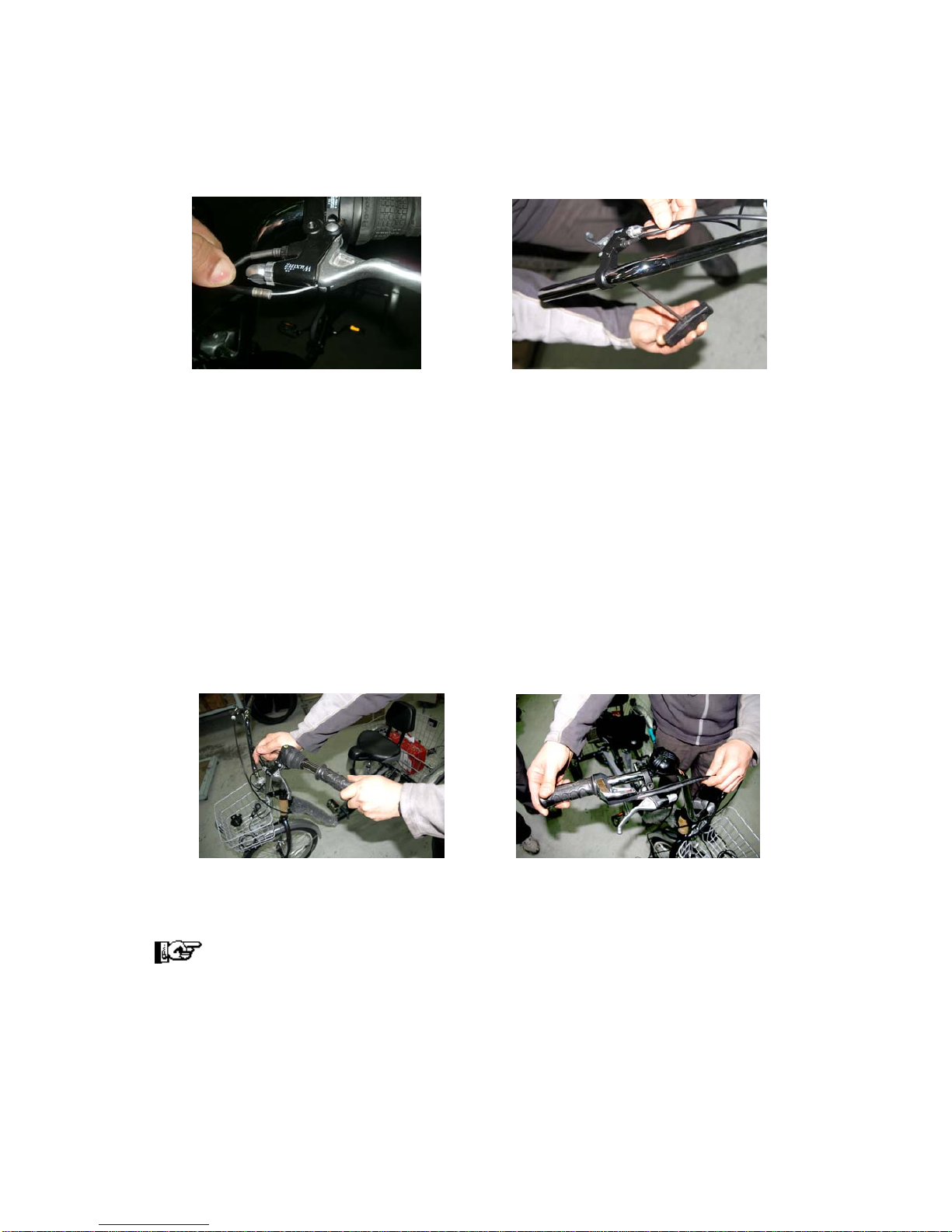
1.2 BRAKE ASSEMBLING / SHIFTING…….....................................................................8
1.2.1 Lever shifting …………………….........................................................................8
1.2.2 Brake levers & shifting grip…..…..……………....................................................8
1.3 ELECTRIC INSTALLATION........................................................................................9
1.3.1 Cables fitting…………........................................................................................9
1.4 CONNECTIONS..........................................................................................................9
1.4.1 Connections parts (Figure 12)…………............................................................10
2 USER’S GUIDE………...................................................................................................12
2.1 TYPE OF USE FOR WHICH THIS KIT HAS BEEN DESIGNED.............................12
2.2 KIT PERFORMANCE……........................................................................................12
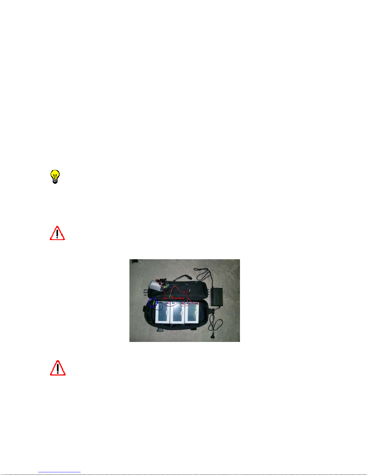
3 BATTERY AND CHARGER……………………………....................................................14
3.1 BATTERY NIVEL INDICATOR.……......................................................................14
3.2 BATTERY CHARGING…..........................................................................................14
3.3 BATTERY FUSE………….........................................................................................16
II PART
4 VERIFICATIONS............................................................................................................17
4.1 VERIFY THE KIT BEFORE THE FIRST RIDING….................................................17
4.2 VERIFICATION POINTS……..................................................................................17
5 SECURITY….................................................................................................................18
5.1 CIRCULATION........................................................................................................18
5.2 NIGHT CIRCULATION…….....................................................................................18
6 ADVICES…...................................................................................................................19
6.1 GENERAL ADVICES……........................................................................................19
6.2 ADVICES TO IMPROVE THE KIT AUTONOMY.....................................................19
6.2.1 PRECAUTIONS TO TAKE INTO ACCOUNT…...................................................19
7 MECHANICAL PARTS AND MAINTENANCE….........................................................20
7.1 AJUSTMENTS.........................................................................................................20
7.1.1 REQUIRED TOOLS….……..................................................................................20
7.2 WHEELS..................................................................................................................20

5
PRESSURE CHART…...................................................................................................20
7.3 LUBRICATION AND CLEANING.............................................................................21
7.4 BRAKES WORK AND PERFORMANCE…..……………….....................................21
7.5 BRAKE CHECKING…..…..................................................................................22
7.5.1 RIM BRAKE SYSTEM………...........................................................................23
7.5.2 VERIFICATION................................................................................................23
7.6 AJUSTEMENT.....................................................................................................23
8 ELECTRONIC COMPONENTS......................................................................................25
8.1 CONTROLLER….......................................................................................................25
8.2 ENGINE......................................................................................................................25
KIT CHARACTERISTICS……..........................................................................................25
ELECTRIC SCHEME….....................................................................................................26
SOLUTION CHART………................................................................................................27
WARANTEE.......................................................................................................................29
FREQUENT QUESTIONS…..............................................................................................29

6
IDENTIFICATION OF THE PARTS
VERIFICATIÓN: Open the KIT box by the cap of the superior part and verify that all the
mentioned parts are being included.
1. Lithium battery
2. Left brake lever
3. Charger
4. Controller
5. Right brake lever
6. Speed control and contact
key
7. Engine front wheel
UNDERSTANDING ICONS
The following icons are to be in order to understand easier this manual and to pay
attention to the most important items.
Go to the other point Advice
Caution Maintenance

7
ELECTRICAL PARTS
1 ASSEMBLING
The Kit assembling must be done in stable position and in horizontal way with some basic
mechanic and electric knowledge. It is advisable to be assembled by an official mechanic.
It is recommended to follow the bellow steps::
Wheel assembling, Brake / control assembling, Electric parts fitting, Connections
1.1 WHEEL ASSEMBLING
1.1.1 FRONT WHEEL REMOVING:
Open the front brake in order that the tyre can pass and set it to the KIT wheel. Loosen
the nuts of the front axle wheel (Figure1) and remove the wheel.
1.1.2 Tyre fitting:
Remove the tyre from the wheel with the help of levers and set it to the KIT. (Figure 2).
Verify if the tyre has sense of direction and fit it rightly. The engine cable gets out from the
left side of the fork in marching order.
Do not miss to set the band rim to protect the tube from the spokes.
1.1.3 KIT wheel assembling to the fork.
Place the washer and nut enclosed to the right axle side of the wheel, fit the wheel to the
fork with the engine cable getting out through the left side.
Fit the washers between the fork and the engine, through the inside part of the fork tubes.
(Figure 3).
Tighten the left and right nuts with a fixed tool of 18 and 17 mm respectively.
Figure 1 Figure 2 Figure 3
1.2 ASSEMBLING OF THE CONTROL COMPONENTS
1.2.1 BRAKE AND SHIFTING ASSEMBLING

8
First loose the nuts of the brake cables in order to take them out through the tensors.
(Figure 4).
Remove the brake levers and the shifting control. (Figure 5).
Loose the brake levers with an Allen of 5mm.
Loose the shifting control with a star screwdriver.
Remove the levers together with the handlebar grips and the shifting control.
Figure 4 Figure 5
1.2.2 Brake and control shifting assembling:
Invert the shifting control and place it to the Leith side.
Remove the brake levers for the ones provided with the KIT with the cable of
disconnection.
Place from inside to outsider by the left side of the handlebar: KIT left brake lever,
shifting control, KIT grips.
Place from inside to outside to the right side of the handlebar: Bell, KIT brake right
lever and the throttle with the KIT contact key.
Adjust them to a handy position and fix the following parts by the following stools:
- Brake levers (Allen 5 mm.)
- Shifting (Star tool)
- Throttle (Allen 3 mm.).
Figure 6 Figure 7
Ensure the brakes to work properly. And the cables well fixed with their respective clamps.
Check the brake mechanical and maintenance section.
1.3 ELECTRIC PARTS ASSEMBLING
1.3.1 Cable sitting/fitting:

9
Fit the brake /speed control electric cables in a parallel position to the brake cables.
Envelope the cables with a spiral band for a correct fixing.(Figure8).
The cables must be set along the frame in a smooth way (Figure 9) to the rear battery
bag where all the connections must be connected Figure 10).
The cables must be set with the right strain: Avoiding the cables to be folded and at the
same time to let them enough loose towards the good handlebar performance.
The engine cable must be guided through the fork side at the head set high of the rest of
the cables. Make sure that the tricycle can turn to both sides without any problem.
The cables must be fixed well to the frame with the clamps, no ends to be let or anything
which can cause any hooking.
Figure 8 Figure 9 Figurae10
1.4 CONNECTIONS
Make the electric connections with the clean and dry hands.
Check the electric scheme and respective figures. In case of any doubt, call at the
customer service number.
Once the battery bag has been set to the rear tyre basket of the tricycle with the Monty
brand looping backwards and the cables well guided and fastened, one must check the
length of them to be right to make the respective connections.
It is possible that the engine cable shall be connected to the electric connection out of the
battery bag.
It is recommended to realize the entry of the cables to the battery bag
through the left side since it is where the controller is set and easy to be
reached by only open a little the zipper.
The controller, an aluminium box where all the cables are being set, is already connected
at factory through the negative cable to the battery. (Figure 11, Blue circle)
One will have to connect the key contact + speed control (throttle) + the brake/engine
levers.
1.4.1 Connection parts (Figure 12):
Contact key + throttle:

10
There are two tubes getting out from the throttle composed by three wires / White,
Black and Red). The three must be connected to the controller through a connecting
link with three wires (Yellow, Black and White)
The thin cable corresponds to the throttle, composed by three wires (White, Black and
Red) and they must be connected to the controller by a connector with three wires (
Yellow, Black and White) respectively.
The big one belongs to the contact key, composed by two wires (Red and Black): The
red must be connected to the red one of the battery (positive) and the Black one to the
Black cable of the controller. (Figure 11, clausor).
Brake levers:
From each brake lever is getting out a cable with two wires Red and Blue) to be
connected to the controller by a link with two wires (Black and Blue). There are two
connectors alike, one for each lever. Connect both levers to them, no matter the order.
Engine:
The engine connection to the controller is being made by a sole tube. The fitting shall
be in a way that the flange of both items is let closed.
The connection of the charger to the battery must only be made when the
battery is going to be charged. Check the battery charging section.
Once all the connections are being set, verify the performance of the KIT.
Turn the contact key to clockwise and the lights of the battery level must be shown.
Turn the throttle and the front wheel is to work.
Make a first try in a secure and free place. The KIT can go forward some m.
before one can control it.
Figure 11
Important: keep the battery by the frame firmly in order not to be removed by
uneven terrains. Not to place anything over the battery.
2 USER’S GUIDE
2.1 TYPE OF USE FOR WHICH THIS BIKE HAS BEEN DESIGNED

11
This KIT has been designed as a complement to our Monty tricycle, providing a help to the
Vehicle to perform trips with a minimum effort.
It is made to be adapted to the Monty tricycle in a very easy way.
ás.
The Monty electric bicycles and their components are being designed as for a normal
bicycle to be used along the standard routes in good state and in good conditions.
Incorrect usage other than the above mentioned or cross-country riding should be
avoided. Ride only along the allowed routes set by the local indications.
ATENTTION: IMPORTANT
This KIT is not to be recommended for kids under the 12 years old.
This KIT is not to be recommended for persons with a superior weight of the 100 kg.
This Kit is made for a non-professional use.
Figure 13 Figure 14
2.2 KIT PERFORMANCE
The electric bicycle or tricycle fitted with the KIT: MONTY E-132 has a simple
performance. It is the same as riding a conventional bicycle but with the help of an engine,
as an electric bicycle.
Steps for a right using:
(First the KIT must be assembled on the whole)
1º Electric connection system:
Turn the contact key a quart to clockwise (Figure 16), the leads from the chart of the
handlebar are to be shown indicating the battery charge level. (Figure15).

12
Figure 15 Figure 16
See: Battery and charger.
2º To initiate the first riding of the vehicle:
One shall Poly press the speed grip (throttle) to go forwards and the engine is to work
automatically. One can regulate the engine speed by the throttle, more you turn the grip,
the quicker the engine is to go, till a maximum speed of 23 km/h.
3º Gears shifting
One shall be used to the changing of the gears: The short ones (1,2,3) to begin the riding
and for the pendent roads and the long ones (4,5,6) for quick riding and even roads.
The pedal help is to improve the performance on the whole system and the lasting of the
battery.
See section: general advises and gear changing
4º How to stop and decrease the speed:
Press the brake lever to stop the KIT, automatically the assisting engine is to stop as well.
See section: General brake advises
IMPORTANT: ON PRESSING THE BRAKE LEVERS, THE EELCTRIC SYSTEM IS
TO STOP THE ENGINE PERFORMANCE AUTOMATICALLY.
IMPORTANT: BEFORE RIDING THE KIT, READ THE FOLLOWING
SECTIONS:“VERIFICATIONS BEFORE RIDING “ AND “SAFET RIDING”
3 BATTERY AND CHARGER
The battery is one of the most important items of the KIT. A correct use of the battery is to
determine its life. The battery must be complete charged before riding the KIT. The
indicator is to show you when the battery has been charged. Make sure the battery to be
fixed to the frame.

13
The KIT is provided with a Lithium battery of 36V-9Ah
The lithium battery provided by the KIT 302 does mot need a precise maintenance but yes
advisable stops to follow:
It must be charged before any riding.
Even stored, the battery must be checked
Avoid the battery to be discharged on the whole.
The batteries can be discharged even if they are not to be used. So it is normal that you
can find the battery down alter a long time of being stored and even if you let the battery
charged on the whole.
3.1 BATTERY CHARGER INDICATORS.
The throttle on the handlebar is provided with a battery charge indicator, Figure (13). If
the right Red Light is shown while one is riding the KIT, it would mean that the battery
capacity is run out, in this case, it should be charged at once.
It is normal the battery to get down on the beginning or getting on a pendent. The indicator
is more reliable riding on even roads.
Figure 17
3.2 BATTERY CHARGE
The battery must be charged on the whole before the first riding. When you receive the
KIT, the battery can be the 50% of its charge.
Use only the charger provided with the KIT, using other chargers, one could deteriorate
the battery.
Keep the battery far from the water in order to avoid shocks. The charger should only be
made in covered places.
The charge of the battery will depend of the discharge which had had. And it can last 5
hours. The charger is to indicate when the battery is already charged.
Important: To charge the battery one must connect to the 220 G from the
general net, once the charger and battery had been connected between them. And
in order to disconnect the same but vice versa.
Steps to follow:

14
1. Remove the charger from the battery bag to get the battery enough ventilation.
Check the charge voltage to be the same than the fuse of the net system (220v).
The charger specifications are impressed on them.
2. First connect the charger cable (B) to the battery connector (A), Figure (18). Make
sure to be well fixed).
3. Second connect the plug of the charger to the socket of the net system
4. To disconnect the whole system: First disconnect the battery from the net system
and later the battery.
Figure 18
Indicator of the level charge.
When the battery is being charged, the red light is being shown. (Figure 20)
When the battery is already charged on the whole, the Green Light is being shown.
(Figure 21)
Very important: Do not allow children to charge the battery by themselves. The
electric charge net (220v), can cause personal serious injuries even death. Do not
charge the battery barefoot on a damp or wet floor or in conditions which threaten
the one personal safety. The sock of the electric system must meet the pertinent
safety conditions.
3.3 BATTERY FUSE
The battery is provided with a fuse of 20ª to avoid of any possible shocks. The fuse is set
inside of the battery. In order to check the fuse, it is necessary to remove the cover by
turning the thread.
The process charge must not last more than 8 hours.

15
If the KIT is not to be used for a long time, the battery should be let charged the 50
% of its capacity and to make a maintenance charge one time per month.
Use always the charger provided with the KIT.
The battery charge is to depend on the consume which had had. It can last 5 hours. The
charger is to advise you when the battery is charged.
The batteries are sensitive to extreme temperatures, in general, the battery performs well
in high temperatures. When the temperatures reach under the 0 Cº, its performance can
go down a third part of its capacity. In winter the distance rate can be inferior and in
temperatures of 20 Cº, its capacity is to be normal.
When the temperatures are superior than the 35º-40º (to be exposed to the sun for a long
time), the electric components can perform in no a right way.
Actions which may effect or reduce the battery performance.
Start and stop the KIT constantly as it can be riding in the city.
Brake, start and stop the KIT constantly.
Ride upwind or uphill and bearing extra weight.
Low tyre pressure and braked wheels.
The above actions mentioned can influence on the battery performance, reducing its
life and the rate to be travelled being shorter. It is recommended to take well note of
them to extend as much possible the travel distance of the KIT. One shall calculate the
distance to travel before going on.
In general the batteries are sensitive to extreme temperatures
The battery charging must be done in a dry and well-ventilated area.
II PARTE
4 VERIFICATIONS
4.1 VERIFYCATIONS BEFORE USING THE KIT FOR THE FIRST
TIME:
• Correct performance of the two brakes:
Front and rear.
• Correct pressure wheels.
• Correct tighten of the pedals.
• Correct tighten of the wheels nuts.
• Correct checking of the folding system.

16
• Correct tighten of the quick releases.
Takes note as normal the following points mentioned below before using the
KIT.
4.2 VERIFICATION POINTS:
WHEELS
The tires and the rims are important parts for the right performance of the KIT. 302. Check
the correct pressure of the tires and the run out of them and the estate of the rims. Make
sure the wheels to be well fixed and placed by their fix system. Avoid water enter into the
bearings.
HANDLEBAR AND STEM
The handlebar and the stem must be fixed in a comfortable and secure position for the
user. The position of the handlebar must be according to the rider. Verify the handlebar to
be well fixed and placed to its position. Never overpass the minimum allowed indicated
stem insertion.
HEAD SET AND FORK
The head set must be checked to turn to both sides free and the whole head set system
not to have play. If the fork is of the suspension kind check everything to be right.
BRAKES
Make sure the brakes to work properly. The brakes must perform and allow to stop the
KIT at a secure distance. On pushing any brake lever, the engine must be disconnected.
Check the run out of the brake shoes or pads.
TRANSMITION
The KIT transmition must be verified in order to work well. It must be kept clean and
lubricated. Not to make strange noises and the changes must be made in a smooth way
and exactly. A good regulation is essential in order to get a good performance of the KIT.
5 SECURITY
5.1 CIRCULATION
Attention to the road
When one is riding must be aware of anything which may pass: Avoid any potholes, the
grids of the drains or edges which could make the wheels to skid. Attention with the turns,
mainly riding the tricycle if you are not sure get off.
Take care with the wet conditions
In wet conditions, the brake system needs to perform stronger than in normal situations
and it shall be calculate more distance for braking.
The rain reduces the visibility and the grip of the wheels as well. Use the low gears on the
turns, on the zebra pass or sleepy areas in rain and wet conditions.
Use the brakes with precaution

17
Keep a moderate distance with the other vehicles and other objects. Calculate the brake
capacity with respect to the distance. Adjust the distance braking capacity.
To stop the KIT, grip both levers at the same time.
The excessive use of the front wheel can provoke a skid on the front wheel, even the rear
wheel may lost contact with the ground.
Take into account that the tricycles fitted with the KIT needs to calculate the brake
distance in advance.
THE CORRECT PERFORMANCE OF THE BRAKES IS VERY IMPORTANT FOR
ONE SECURITY AND OF THE OTHERS. VERIFY THE BRAKES BEFORE ANY RIDING
AND DO NOT USE IT IN CASE OF NOTICING SOMETHING FAULT.
5.2 NIGHT RIDING
Take care with poor luminosity
Be prudent on riding with poor Light. The KIT is provided with a light and reflector set.
Keep them well clean and in the right position. Thought the reflectors are items to be
seen, they do not light up. Use a front light and rear one under poor conditions. It is
convenient to bring striking and reflecting clothing, especially during the night.
6 ADVICES
6.1GENERAL ADVICES:
Take care on overtaking cars or other vehicles
Do not make insecure actions while riding
Respect and be aware of the circulation rules
The local illumination rules must be known
Protect the KIT from the thieves
The KIT should be registered in the local police
Provide your KIT with a lock
No person to be brought at the rear carrier
Use and set the right gears
Bring a toll for everything and a fist-aid kit
Use always the Helmet protector
6.2 ADVISES TO IMPROVE THE AUTONOMY
Set the gears 1 and 2 to start and help the engine by pedalling.
Help the engine by pedalling on the pending roads.

18
Do not use the speed grip constantly
Keep the tires pressure to be right
Verify the rakes not to touch the rims.
Keep a media speed if it is possible.
When the KIT had to be stopped, use the brakes in a carefully way, letting the KIT
losing speed by itself.
Do no to over pass the allowed weigh
If the system lights provided with the KIT is supplied by the battery, use them only in
necessary moments.
6.2.1 Preventive measures on using the KIT.
1. In order to brake or to stop the KIT, the user will have to press both brake levers,
depending on the circumstances, the engine is to be disconnected automatically. To take
into account the brake lever system: Same system like the bicycle: The left brake lever
brakes the front wheel and the right lever brakes the rear wheel.
2. This KIT is only to be used by one sole person.
3. Reduce the speed on rainy days in order to avoid any accident.
4. Avoid using the KIT in bad days: Rain and snow.
ATTENTION: The brake lever position can be inverted in some countries.
The autonomy and performance of the KIT depend on different factors:
These can be classified in two types:
External factors: The usual from the environment conditions (surface, climate, etc).
Internal factors: They are the ones corresponding to the bicycles state, riding style..
The external factors little can it be done.
The internal factors: They can be improved depending on the use and maintenance of the
KIT. It is possible to last the life of the battery and the run out of the components.
Use the gears 3 or 4 in an even surface an Light pending.
Use the gears 5 and 6 in Haig speed and in descent.
In order to chain the gears, get down the pedal force, press the shifting and go pedalling.
The gears must be changed one by one.
Use the gears 1 and 2 to stop the KIT.
Note: Not to change the gears while the KIT is stopped and the gears must be changed
one by one.

19
ATENTION: As any mechanical device, the KIT is to wear down
along the time. The different materials and components used react
differently to this daily decline. If the lasting of any item has been
finished it can be broken, causing injuries to the user. The cracks,
scratches or discoloration of the items can be a signal of intense use,
therefore they should be changed.
7 MECHANICS POINTS AND MAINTENANCE
7.1 AJUSTMENTS
7.1.1 REQUIRED TOOLS
It is recommended to be provided with the standard tools to repair the KIT. The majority of
the suggestions and advises can be made with standard tools. However, sometimes, it is
advised to go to the official distributor for special adjustments.
Usual tools:
- Star and plane screwdriver
- Allen tools (3, 4, 5, 6 mm)
- Fixed tools. (8-9,10-11,14-15,18-19mm)
- Pincers
Caution: A wheel in poor conditions may cause the user lost the control and
possible falls. Check the wheels each time before riding and do not use the KIT if
one has detected a problem.
7.2 WHEELS
TIRES
The tires must be in good state and the thread not to be cracked or either to be run out.
They must keep the grip as the first day of riding. The size of the tires is being indicated

20
on them. On changing the tires, make sure them to have the right size to the rim and the
Vehicle type.
CAUTION: On replacing the tyre, make sure to have taken a tyre compatible
with the rim and type for the KIT. The KITS tires have special characteristics
different from standard ones.
Tyre pressure
Tires must be inflated to the right pressure to ensure the KIT to work properly. That is to
say::
- With a high pressure, it is to be achieved a greater speed, though, the riding is to be less
comfortable to the user and the risk of falling on curves or slippery surfaces.
- With a media pressure greater comfort is to be achieved.
The valve is like the “American” type as the ones used by the cars. However, it should be
avoided filling the tires at the petrol stations, etc. Use a pump with suitable nozzle to the
valve.
To inflate the tyre, remove the valve cap and place the nozzle on the valve, ensuring air
not to be gone out. Check the pressure and place the valve cap to keep it from getting
dirty.
In case the tubes got flat, it is advisable to change them, instead of being repaired.
Remind: The maximum tyre pressure allowed is set at the edges of the tires
Before using the KIT, the tire pressure should be checked ( inflate the tires
without exceeding the limit printed on the lateral sides of the tires), the tires wear,
their fitting and the alignment to the rims.
PRESSURE CHART
Wheel Maximum pressure Recommended
pressure
Bar KPa PSI Bar KPa PSI
Front 3,5 350 50 2,0 200 29
Rear 3,5 350 50 2,0 200 29
EQUIVALENCE (Aprox.): 1 Bar = 100 KPa = 14,5 PSI
CAUTION: The excessive run out of the tires can cause a faulty tyre fitting
provoking injuries to the user. Do not use rims shown a clear run out.
7.3 LUBRICATION AND CLEANING
Other manuals for E-132
1
Table of contents
Other Monty e-bike Bicycle manuals