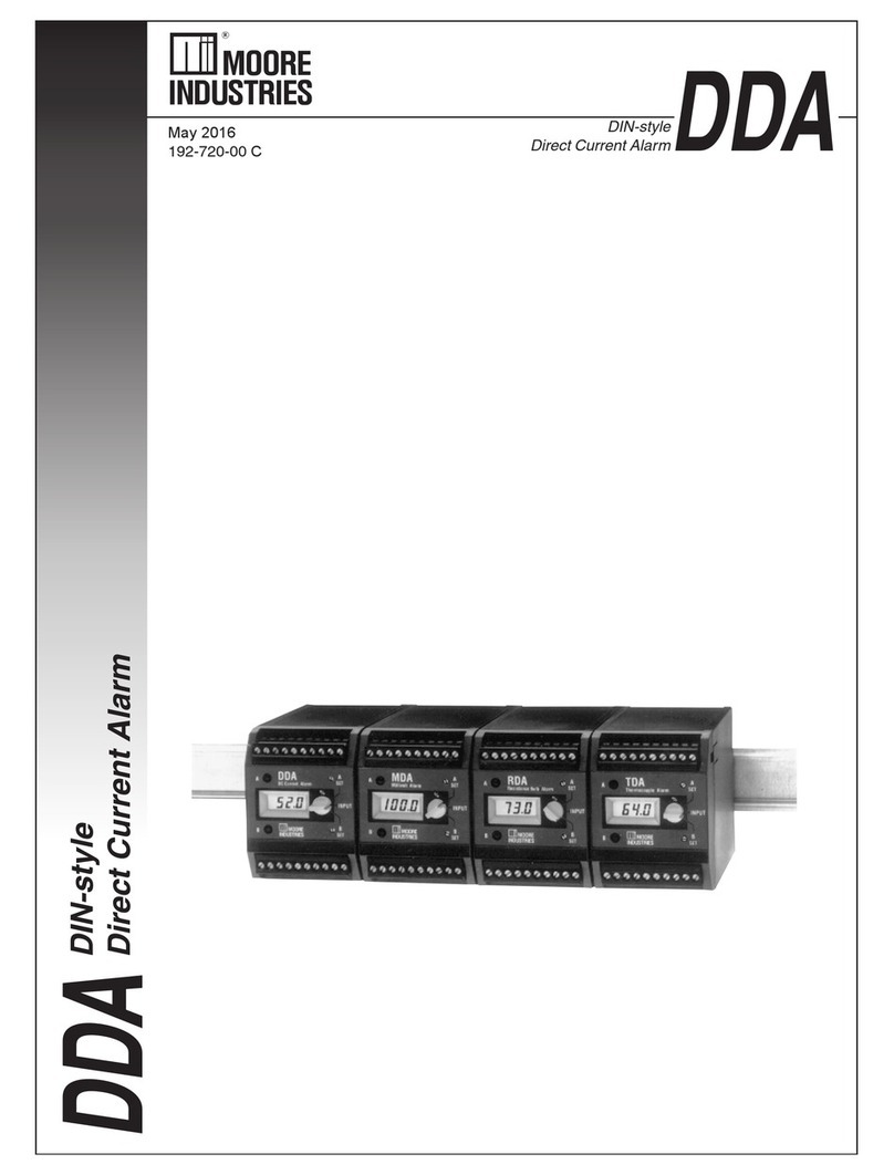
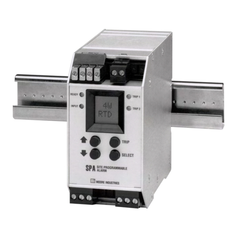
Moore Industries SPA HLPRG User manual

The Interface Solution Experts 1
SPA
SPA
April 2016
224-715-00D
Site-ProgrammableVolt &
Milliamp Limit AlarmTrips
HLPRG
Site-Programmable Volt & Mil-
liamp Limit Alarm Trips

2 The Interface Solution Experts
ENTER
PASS
Enter the password
code to enable
settings changes.
(Default = 55)
Scale Input "Smart Scaling":
Set the values to be displayed
at zero and full scale without
calibration equipment.
Trim Output:
Connect the SPA into a calibration
setup as shown in the manual and
trim the analog output.
(Requires –AO Option)
Select Volt or Current Input:
Select input type. Defaults to mA.
Password:
View or change password.
Apply Input "Bench Scaling":
Using calibration equipment,
capture the zero and full scale
values.
Exit Configuration Menu:
Return to process display.
Configure Function Options:
Set engineering units, and custom
or standard linearization mode.
Security Jumper
installed in OFF position. Security Jumper
installed in ON position.
VIEW current settings
Front Panel
Push Buttons
Inactive during operation.
SELECT
Use or push buttons to scroll
through menus and sub-menus.
Use SELECT push button to access
menu and/or make a choice.
VIEW
SEL
V/I
CONF
OPTS
SCLE
INPT
APLY
INPT
TRIM
OUT
CONF
EXIT
CONF
ALRM
Configure Alarm:
Set trip point, deadband,
high\low trip, delay, and
latching\non-latching.
PASS
WORD
Enter Custom Curve:
Program up to 20 linearization
points into memory.
(This menu is only available if
SCLE
DSPL
Scale the Display:
Custom-scale the display.
(This menu is only available if
ENTR
CURV
Scale Analog Output:
Connect the SPA into a calibration
setup as shown in the manual
and trim the analog output.
(Requires –AO Option)
SCLE
AO
SPA HLPRG Quickstart Guide
Use the front push-buttons to quickly and
easily setup the SPA for your application.
After programming your alarm using the
diagram below, install the unit into your
application using the connection diagram
and terminal designation table on pages
35 and 36 of this manual.

The Interface Solution Experts 3
Table of Contents
SPA Volt/Milliamp AlarmTrips............................................................................4
Programmable Inputs...........................................................................................................4
Programmable Outputs........................................................................................................4
Programmable Display.........................................................................................................4
Programmable Input Failure Alarms.....................................................................................4
Universal Mounting ..............................................................................................................4
Specifications.....................................................................................................5
AlarmTerminology .............................................................................................6
Internal Settings .................................................................................................7
Programming the HLPRG SPA..........................................................................9
Main Menu/View Settings.....................................................................................................9
Password............................................................................................................................11
Select Input Type................................................................................................................12
Configure Function Options ...............................................................................................13
Scaling Input – “Smart Scaling” the HLPRG ......................................................................15
Applying Input – “Bench Ranging” the HLPRG..................................................................17
Scaling the Display – Setting the Engineering Units in Custom Mode...............................19
Programming SPA Linearization – Entering Segment Endpoints in Custom Mode ...........21
Scaling the Analog Output – SPAs with AO.......................................................................25
Trim Output.........................................................................................................................25
Configure Alarm(s).............................................................................................................28
Change the Security Password Code ................................................................................32
Installation.........................................................................................................33
Mounting ............................................................................................................................33
Connections.......................................................................................................................34
Operation.......................................................................................................... 37
LEDs ..................................................................................................................................37
Manual Reset.....................................................................................................................37
Error Codes........................................................................................................................38
Customer Service.............................................................................................38

SPA
4 The Interface Solution Experts
Site-Programmable Volt &
Milliamp Limit Alarm Trips
SPAVolt/Milliamp AlarmTrips
This is the users’manual for theVolt/Milliamp Input
model of the Moore Industries’ Site-Programmable
process Alarms (SPA). The SPA monitors a process
variable and provides up to four, fully configurable,
contact closure outputs whenever that input falls
outside a user-set, high or low trip point. SPAs are
typically used to activate a warning light, bell, or
buzzer; or to initiate a system shutdown, thus acting as
simple, but highly reliable and effective means of safe-
guarding a process.
Programmable Inputs
The Programmable Current/Voltage unit, or HLPRG
SPA (for “High Level” Programmable input), handles
either current or voltage inputs in any user-set span
in a 0-50mA or 0-10V range. The HLPRG comes
standard with transmitter excitation capability for use
with 2-wire loop transmitters.
Programmable Outputs
The SPA HLPRG can be equipped with a fully
scaleable analog output (-AO) option with the capacity
of being switched by the user to either 0-20mA (source
or sink), or 0-5V.
The source/sink setting for the optional analog output
is controlled by DIP switches that are located behind
an easy-to-remove access panel inside the unit’s
housing.
Programmable Display
With the Volt/Milliamp Input SPA, the user can choose
between the Linear function mode and the Custom
function mode.
In the Linear Mode, the SPA HLPRG behaves much
like a simple input meter. The display is set by the
user to show the input in either mA or volts. Its scaling
is tied to any input scaling performed. (If equipped
with the –AO option, the SPA’s output can be scaled
independent of the input.)
The SPA HLPRG’s Custom Mode sets the unit up for
independent programming of input scaling, display
scaling, and, if equipped with the –AO option, output
scaling. In Custom Mode, the user selects °C, °F, % of
scale, Blank (for raw display), or a pre-specified
4-place custom engineering unit label.
Programmable Input Failure Alarms
The SPA can be ordered with 1, 2, 3, or 4 contact
closure alarms. Each alarm can be individually
programmed for a different trip point, deadband, delay,
high or low alarming, latching or non-latching, and
failsafe or non-failsafe operation.
The SPA also provides two ways to set the alarm
trip point. If an input source is either unavailable or
inconvenient, the unit’s front panel push buttons and
integral liquid crystal display (LCD) can be used to
enter the desired trip point.
When a source is available, the SPA can capture
trip points by setting the input to the desired trip and
pressing the appropriate button.
Failsafe or Non-failsafe alarm functioning is controlled
by DIP switches that are located behind an easy-to-
remove access panel inside the unit’s housing.
Universal Mounting
The SPA is housed in a “universal” DIN case that can
be mounted on both 32mm G-type (EN50035) and
35mm Top-Hat (EN50022) DIN-rail. The Installation
section of this manual gives the dimensions of the
housings for the various SPA configurations.
The Interface Solution Experts 5
SPA
Site-Programmable Volt &
Milliamp Limit Alarm Trips
Specifications
Repeatability: Trip point
repeats within ±0.05% of
input span
Display Accuracy: ±1
digit;When scaling the dis-
play (in Custom Mode), high
input-to-display span ratios
decrease display accuracy
Input Accuracy:
Current input, ±5µA;Voltage
inputs, ±1mV
Stability: ±0.1% of
calibrated span, maximum,
over 6 months
Deadband: 11.5V or
57.5mA, maximum in Linear
Mode; equivalent of maxi-
mum input range in user-set
engineering units in Custom
Mode
ResponseTime: 600 mil-
liseconds (Defined as time
from step change on input
to alarm state change when
alarm
is set to trip at mid-
point) AlarmTrip Delay:
Programmable from 0-60
seconds
LineVoltage Effect:
±0.005% of span for a
1% change in line voltage
(ac or dc)
Isolation: 1000Vrms
between case, input, output
(units with -AO option) and
power terminals (NOTE:
High voltage effect of
±0.0004% of output
span/V possible with
prolonged exposure to ac
voltage above 200Vac)
Power Consumption:
2-4W, nominal;
6W, maximum
Performance Performance
(continued) Ambient
Conditions
(continued)
Adjustments
Weight
Input Impedance: 1MΩfor
voltage inputs; 20Ωnominal
for current inputs
Input Over-Range Protec-
tion: 18Vdc for voltage
inputs; 180% of maximum
input span
WITH ANALOG OUTPUT
Output Accuracy: ±0.03%
of output span (includes the
combined effects of linear-
ity, hysteresis, repeatability,
and adjustment
resolution)
ResponseTime: 250
msec maximum time for
output to go from 10% to
90% for step change on
input
Ripple (up to 120Hz):
Current output, 10mV
peak-to-peak max. when
measured across a 250Ω
resistor; Voltage output,
15mV peak-to-peak max.
Output Limiting: 117% of
span max., 115% of span
typical
Load Effect: ±0.01% of
span from 0 to maximum
load resistance on current
output
Operating Range:
–25°C to +65°C
(–13°F to +149°F)
Storage Range:
–40°C to +80°C
(–40°F to +176°F)
AmbientTemperature
Effect: ±0.005% of outut
span per °C maximum;
±15ppm of input signal
Relative Humidity:
0–95% non-condensing
RFI/EMI Protection:
30V/m - ABC ≤0.5% error
in reading when tested ac-
cording to SAMA standard
PMC 33.1
Common Mode Rejection:
100dB @ 60Hz
Normal Mode Rejection:
40dB @ 60Hz (measured
w/current input)
Front panel push buttons
control settings for zero,
span, alarm trip points,
high/low alarms, etc.; Easy
access internal settings
select current (source or
sink) or voltage output, and
failsafe or
non-failsafe alarm func-
tions; Internal jumper and
menu password protect
parameter settings
LCD: 2x4 character, back-
lit, alphanumeric readout
accurate to the nearest
digit.
Range: -9999 to 9999;
Decimal point can be user-
set when in Custom Mode
LED’s: Dual-color TRIP
light (one for each relay)
shows green for non-alarm,
red for alarm; READY light
indicates normal operation,
extinguishes in the event of
any internal failure;INPUT
light is always green
456 to 513 g
(16.1 to 18.1 oz)
Ambient
Conditions
Indicators
Performance
with Analog
Output (-AO
Option)
Specifications and information subject to change without notice.

SPA
6 The Interface Solution Experts
Site-Programmable Volt &
Milliamp Limit Alarm Trips
AlarmTerminology
Before setting up the SPA, or incorporating the unit
in your application, Moore Industries suggests that
all users take a few moments to become familiar with
some of the terms associated with the use of process
instrumentation alarms. Figure 1 illustrates the way
the SPA alarms operate.
The Trip Point is the process input level at which the
user wants an alarm relay to change state, typically
going into an alarm condition, or “tripping”. In the SPA,
the user sets the trip point for each installed relay.
High\Low Alarms: High Alarms trip when the process
input goes above the trip point. Low Alarms trip when
the process input drops below the trip point. Each
of the SPA outputs can be set by the user to function
independently as either high or low alarms.
Latching and Non-latching Alarms; once tripped, a
latching alarm remains in alarm until the input returns
to a non-alarm level AND is manually reset.
Non-latching alarms return to a non-alarm state
whenever the process input returns to the Reset Point.
The SPA relays can be set by the user to function as
either latching or non-latching.
Figure 1. How Alarms Work with the Process Input
The Reset Point is the process input level at which the
user wants an alarm relay to change state, typically
going from alarm to non-alarm. The reset point is
not necessarily the same as the trip point, because
most applications call for a buffer zone or “Deadband”
around the trip point to allow for minute fluctuations
in the process input. In the SPA, the reset point is
determined by the deadband setting. Latching SPA
alarms will not “clear” unless the reset point has been
reached or passed AND the manual reset contacts
have been shorted.
The Deadband is the range in which an alarm remains
tripped even after the process input has returned to
or passed the trip point. Deadband is not required.
When it is not incorporated into an alarm application,
the trip point and reset point are the same. The
deadband of the SPA is set by the user.
Failsafe Alarms are de-energized when tripped,
energized when the process input is at a non-alarm
level. Non-failsafe Alarms are energized whenever
tripped, de-energized when the process input is at a
non-alarm level. The relays in the SPA can be switched
from failsafe to non-failsafe at any time by the user.
Normal is the term used to describe the “shelf-state” of
relay contacts. The contacts of a Normally Open relay
are open (infinite resistance) when the relay is not
energized. The contacts of a Normally Closed relay
are open when the relay is energized (closed when not
energized).
NOTE:
Sometimes a non-alarm input level is referred
to as being in a “normal” condition. This
practice is intentionally avoided in this manual.
Do not confuse the term “normal”, as in
Normally Open or Normally Closed, with a
non-alarm input condition. In this manual,
“normal” is an exclusive reference to the shelf
state or quiescent state of an alarm’s relay
contacts, whether open or closed.
HIGH ALARM
TRIP POINT
LOW ALARM
TRIP POINT
DEADBAND
RESET DEADBAND
RESET
IN ALARM
IN NON-ALARM
TIME

The Interface Solution Experts 7
SPA
Site-Programmable Volt &
Milliamp Limit Alarm Trips
Internal Settings
The Failsafe/Non-failsafe relay and the password
security functions of the SPA are controlled by means
of simple DIP switches and a single jumper inside the
unit housing.
If the unit is equipped with the AO option, voltage and
current sink/source selection is also inside.
The SPA housing is fitted with a sliding access door in
its bottom panel. Figures 3, 4, and 5 show the panel
and the location of each of the controls for setting:
• PasswordSecurityON/OFF(Figure 2)
• Failsafe/Non-failsafeAlarmFunction (Figure 3)
• CurrentSource/SinkorVoltage(Figure 4)
(Available in AO-equipped SPAs only)
NOTE:
SPAs equipped with the DPDT option make
use of switches 1 and 2 only (see Figure 3).
Figure 2. Setting the Internal Jumper for Password Security ON or OFF
SLIDING PANEL
SPA UNDERSIDE SET PASSWORD SECURITY
PASSWORD SECURITY
IS ON. PASSWORD
REQUIRED.
PASSWORD SECURITY
IS OFF. PASSWORD
NOT REQUIRED.
NOTE: THE THREE PINS TOWARD THE LEFT SIDE OF THE COMPARTMENT
ARE FOR FACTORY TESTING ONLY.
DO NOT INSTALL JUMPERS ON THESE PINS!
BACK
NO1
CM1
NC1
NO2
CM2
NC2
GND
RELAY 1 RELAY 2 POWER
AC OR DC

SPA
8 The Interface Solution Experts
Site-Programmable Volt &
Milliamp Limit Alarm Trips
Figure 4. Setting the Internal DIP Switches for Current Source/Sink or Voltage (AO-equipped SPAs only)
Figure 3. Setting the Internal DIP Switches for Failsafe or Non-Failsafe Alarm Function
FAILSAFE
=
NON-FAILSAFE
=
SET FAILSAFE/NON-FAILSAFE
1234
EXAMPLE:
ALARMS 1 & 2 = NON-FAILSAFE
ALARMS 3 & 4 = FAILSAFE
BACK
NO1
CM1
NC1
NO2
CM2
NC2
GND
RELAY 1 RELAY 2
POWER
AC OR DC
FRONT
SPA UNDERSIDE
NOTE: THIS 4-POSITION SIP SWITCH MAY VARY IN LOCATION BASED ON THE TYPE OF SPA USED
FRONT
SPA UNDERSIDE
GND
POWER
AC OR DC
(terminal
labeling)
BACK
SOURCE
CURRENT SINK
CURRENT VOLTAGE
SLIDING
PANEL
SET CURRENT-SOURCE/SINK OR VOLTAGE

The Interface Solution Experts 9
SPA
Site-Programmable Volt &
Milliamp Limit Alarm Trips
Programming the HLPRG SPA
The High Level Input SPA operating parameters are
set, and the settings are stored in on-board, non-
volatile EEPROM. There are four push buttons on the
unit front panel;VIEW, SELECT, an UP arrow, and
a DOWN arrow. Together with the prompting mes-
sages displayed on the LCD, these are used to access
menus, and to view and change the settings for:
•Select InputType: current (I) or voltage (V)
• Select Functional Setting (Linear Mode or Cus-
tom Mode) and, if selected, set Custom Mode
Engineering units.
• ScaleInput—SmartScaling
• ApplyInput—BenchScaling
• ScaleDisplayreadout
• SetLinearizationCurve(CustomModeonly)
• ScaleAnalogOutput(AO-equippedunitsonly)
•Trim Analog Output (AO-equipped units only)
•Configure Alarm Functions (Trip points, etc.)
•Change/View Password
Main Menu/View Settings
Figure 5 gives an overview of the first level of menus
used to configure the SPA.
On power-up, the SPA defaults to a display of the
measured value. Pressing the VIEW button accesses
a series of displays that show, in succession, the set-
tings currently stored in unit memory (see Figure 6).
Depending upon whether or not the Security Jumper
has been installed (see Figure 2), SELECT will access
either the first screen in the main configuration menu,
“SEL V/I”, or the password code query screen, “ENTR
PASS”.
Once the Main Menu has been accessed, the up and
down arrow buttons are used to move through all of
the sub-menus in a loop. Pressing the SELECT button
accesses the first screen of the sub-menu shown on
the LCD.

SPA
10 The Interface Solution Experts
Site-Programmable Volt &
Milliamp Limit Alarm Trips
Figure 5. The HLPRG SPA Main Menu
DISPLAY OF
PROCESS
VALUE
VIEW
SELECT
VIEW
SETTINGS
MODE
IS THE
SECURITY
JUMPER
INSTALLED?
NO
YES
ENTER
PASS
##
PASS
IS THE
DISPLAYED
PASSWORD
CORRECT?
READ
ONLY
READ,
BUT DO NOT
CHANGE
CURRENT
SETTINGS
NO
YES
SCLE
AO
CONF
ALRM
CONF
OPTS
ENTR
CURV SCLE
DSPL
PASS
LOCK
1SKIPS TO UNLESS CUSTOM MODE IS SELECTED IN
2SKIPS TO
3UP FROM HERE SKIPSTO
4IN READ ONLY MODE SCREEN SHOWS
UNLESS AO OPTION IS INSTALLED
UNLESS AO OPTION IS INSTALLED, OR TO UNLESS IN CUSTOM MODE
VIEW
SELECT
VIEW
SELECT
VIEW
SELECT
VIEW
SELECT
VIEW
SELECT
VIEW
SELECT
VIEW
SELECT
VIEW
SELECT
VIEW
SELECT
VIEW
SELECT
VIEW
SELECT
VIEW
SELECT
VIEW
SELECT
VIEW
SELECT
INCREASE ##
DECREASE ##
DEFAULT
IS "55"
CHOOSE CURRENT
OR VOLTAGE
(DEFAULTS TO mA)
CONFIGURE
OPTIONS
SCALE INPUT
"SMART SCALING"
APPLY INPUT
"BENCH SCALING"
SCALE DISPLAY
(CUSTOM MODE ONLY)
ENTER
LINEARIZING
CURVE (CUSTOM
MODE ONLY)
SCALE
ANALOG OUTPUT
(AO-EQUIPPED ONLY)
TRIM
ANALOG OUTPUT
(AO EQUIPPED ONLY)
SET ALARM
PARAMETERS
CHANGE
PASSWORD
CODE
EXIT MAIN MENU AND
RETURN TO DISPLAY
OF PROCESS VALUE
SEL
V/I
CONF
OPTS
SCLE
INPT
APLY
INPT
SCLE
DSPL
ENTR
CURV
SCLE
AO
TRIM
OUT
CONF
ALRM
PASS
WORD
CONF
EXIT
CONF
EXIT
VIEW
SELECT
000.0
DEG C
VIEW
SELECT
000.0
DEG C
21
3
4

The Interface Solution Experts 11
SPA
Site-Programmable Volt &
Milliamp Limit Alarm Trips
Figure 6. The HLPRG SPA View Mode
Password
This menu is bypassed if the Password Security
Jumper is not installed (see Figure 2). If the jumper
is installed, the menu comes up when SELECT is
pressed from the display of the process variable input.
The flow chart is shown as part of Figure 5.
1. If the jumper is installed, pressing SELECT
from the display of the process variable
input will bring up the “ENTR PASS”
screen.
2. Use the up or down arrow buttons, or
press SELECT again to access “55 PASS”,
the default screen for this point in the
menu.
3. Use the up or down arrow buttons to
display the correct password.
When the correct password number is
displayed, press SELECT.
NOTE:
If the correct password is not known, the unit
settings can be viewed, but not changed, as
shown in Figure 17.
4. If you have entered the correct password,
the Select InputType menu, “SEL V/I”, will
be accessed. If not, the display will show a
“READ ONLY” message.
5. From “READ ONLY”, press SELECT to
view the settings in the various menus.
READ ONLY mode locks out any attempt
to make changes to the settings.
Press the up or down arrow buttons to
return to “55 PASS” from “READ ONLY”.
NOTE:
The menu to set or change the Password
stored in SPA memory is presented later in
this section of the manual.
VIEW
SELECT
000.0
DEG C
VIEW
SELECT
VIEW
SETTINGS
MODE
IS THE
SECURITY
JUMPER
INSTALLED? NO
YES MAIN
MENU
(FIGURE 6)
PASSWORD
MENU
(FIGURE 6)
####
ZERO
####
FULL
####
AL1x
IS
ANOTHER
ALARM
INSTALLED? NO
YES
####
AL#x
VIEW
SELECT
VIEW
SELECT
VIEW
SELECT
VIEW
SELECT
ZERO SETTING
IN MEMORY
FULL SCALE SETTING
IN MEMORY
TRIP POINT & HI/LO
ALARM SETTINGS
FOR RELAY #1
EXIT VIEW SETTINGS MODE
AND RETURN TO DISPLAY
OF PROCESS VALUE
SHOWS
PARAMETERS
OF NEXT RELAY

SPA
12 The Interface Solution Experts
Site-Programmable Volt &
Milliamp Limit Alarm Trips
Select InputType
The menu for selecting the input type for the High
Level SPA is shown in Figure 7.
If the Password Jumper is not installed, the password
sub-menu is bypassed, and the Select V/I menu is
accessed by pressing SELECT from the display of the
measured input value.
1. From the “SELV/I”display, press SELECT.
2. Use the up or down arrow buttons to scroll
through the two options for input type. The
default display for this menu is always the
last setting.
3. When the display shows the type of input,
current or voltage, that is to be used with
the SPA, press SELECT.
4. The next display is the menu for
the selection of functional options,
”CONF OPTS”. To skip the rest of the
configuration menus and return to the
display of the measured input value, press
the up arrow button 2 times (to “CONF
EXIT”), and press SELECT.
Figure 7. Selecting the HLPRG Input Type
VIEW
SELECT
VIEW
SELECT
FROMTHE
MAIN MENU
CONF
EXIT
MA
0 50 VOLT
0 10
VOLT
0 10 MA
0 50
CONF
OPTS
VOLT
0 10 MA
0 50
SEL
V/I
TOGGLE
TOGGLE
DEFAULTS TO
LAST SETTING
RETURNS TO MAIN MENU

The Interface Solution Experts 13
SPA
Site-Programmable Volt &
Milliamp Limit Alarm Trips
Configure Function Options
This menu allows the user to choose between Linear
and Custom modes of functioning.
Linear Function. In its Linear Mode, the HLPRG SPA
behaves much like a simple input meter. The display
is set by the user to show the input in either mA or
volts. Its scaling is tied to any input scaling performed
(set in another menu). If equipped with one of the AO
options, SPA output also can be scaled independently
with respect to the input.
Custom Function. The HLPRG’s Custom Mode sets
the unit up for independent programming of input
scaling, display scaling, and, if equipped with the AO
option, output scaling. In Custom Mode, the user can
select °C, °F, % of scale, or Blank (for raw display);or
a user-specified, 4-place engineering unit, set at the
factory.
Also, if Custom Mode is selected, the user can select
either linear or non-linear display scaling, which en-
ables a user-programmed, 20-point linearization set in
a separate menu.
NOTE:
The SPA’s Linear Mode and its linearizing
of the Custom Mode functioning are not the
same. Refer to Figure 8.
Figure 8 gives an overview of the HLPRG SPA
Configure Options menu.
1. From the “CONF OPTS”screen of the
Main Menu, press SELECT. This brings up
“SET FUNC”, which is the access screen
for choosing between Linear and Custom
Function Modes.
2. Press SELECT again to set the desired
function mode, or use the arrow buttons
to move to“EXIT OPT” and bypass the
Select Options procedure.
Note that, depending upon the Mode
setting, it may be necessary to bypass
“SET LIN”screen.
3. With “SET FUNC” showing on the LCD,
use the arrow buttons to toggle between
“CUST FUNC”and “LINR FUNC”. Refer
to the explanation above for information
about each of the operating modes.
4. When the LCD shows the desired mode,
press SELECT.
5. If “CUST FUNC” was selected, go to
step 7.
6. If “LINR FUNC” was selected, the LCD will
now show “EXIT OPTS”.
Use the arrow buttons to return to “SET
FUNC”(step 3), or press SELECT to
return to the Main Menu.
7. Press SELECT to begin the process of
setting the desired engineering units to be
displayed during HLPRG operation.
8. Use the arrow buttons to“scroll” through
the available options.
9. When the appropriate units are showing
on the LCD, press SELECT.
This brings up a sub-menu that allows
the user to choose between a linearized
or non-linearized display of the selected,
custom engineering units.
10. Use the arrow buttons to toggle
linearization on or off, then press SELECT
to go to “EXIT OPTS”.
11. Press SELECT again (from “EXIT OPTS”)
to return to the Main Menu, or to correct
any mistake, go to step 2.

SPA
14 The Interface Solution Experts
Site-Programmable Volt &
Milliamp Limit Alarm Trips
Figure 8. The HLPRG SPA Configure Options Menu
CONF
EXIT
SCLE
INPT
EXIT
OPT
LINR
FUNC CUST
FUNC
CUST
FUNC LINR
FUNC
CUST
FUNC
LINR
FUNC
EXIT
OPTS
CUST
EXIT
OPTS
SET
FUNC
CONF
OPTS
CONF
OPTS
LIN
OFF LIN
ON
LIN
ON LIN
OFF
DEGC
SEL
V/I
CONF
OPTS SET
FUNC CUST
FUNC LINR
FUNC
SET
EGU
DEGC
DEGF
PCT
BLNK
CSTM
EXIT
OPTS
LIN
OFF
LIN
ON
EXIT
OPTS
SET
LIN
CUST
FUNC
LINR
FUNC
WHAT IS THE
FUNCTION MODE
OF THE UNIT?
RETURN TO
THE MAIN MENU
CHOOSE CURRENT
OR VOLTAGE
(DEFAULTS TO mA)
VIEW
SELECT
VIEW
SELECT VIEW
SELECT VIEW
SELECT
?
VIEW
SELECT
VIEW
SELECT
SELECT
SELECT
VIEW
SELECT
VIEW
SELECT
VIEW
SELECT
VIEW
SELECT
VIEW
SELECT
VIEW
SELECT
VIEW
SELECT

The Interface Solution Experts 15
SPA
Site-Programmable Volt &
Milliamp Limit Alarm Trips
ScalingInput—
“Smart Scaling” the HLPRG
This feature of the HLPRG SPA allows users to set
the zero and full scale values of the input from the
intended application without having to connect the unit
to any calibration equipment.
With Smart Scaling, the LCD and menus are used
to enter the value for zero and full scale, in either
milliamps or volts.
Once these two input parameters are set, the HLPRG
automatically routes the user to the next appropriate
menu; Scale the Display, for Custom Mode users;
Scale the Output, for Linear Mode users (with AO-
equipped HLPRG SPAs); or Configure Alarms, for
Linear Mode users whose units are not equipped with
analog output.
Figure 9. shows the Smart Scaling menu.
1. From the readout of“SCLE INPT”on the Main
Menu, press SELECT.
2. Use the arrow buttons to “scroll”from“SET
ZERO”to “SET FULL”, or to “EXIT SCLE”to
abort Smart Scaling and return to the Main
Menu.
3. When the desired parameter shows on the
LCD, press SELECT.
The LCD will show the engineering units
selected in Configure Options menu,
discussed previously in this section.
4. Use the arrow buttons to set the display to
show the known zero or full scale input from
the intended application. Holding the push
button in accelerates the display change.
5. When the LCD shows the correct setting, press
SELECT.
6. If “EXIT SCLE”is showing and both zero and
full scale have not been set, go to step 2.
7. If both the zero input and full scale input
parameters have been entered into the SPA
memory, go to step 9.
8. Go to step 4.
9. Use the arrow buttons to “scroll”to“EXIT
SCLE”and press SELECT.
If the SPA Custom Mode was selected in the
Configure Options menu, the next menu shown
will be Scale the Display, since in Custom
Mode the input, display, and output (if present)
are independent.
If the SPA Linear Mode was selected in the
Configure Options menu, the next menu shown
will either be Scale Analog Output, for units
equipped with an AO option, or Configure
Alarms.

SPA
16 The Interface Solution Experts
Site-Programmable Volt &
Milliamp Limit Alarm Trips
Figure 9. Smart Scaling the HLPRG SPA Input
VIEW
SELECT
VIEW
SELECT
VIEW
SELECT
VIEW
SELECT
VIEW
SELECT
VIEW
SELECT VIEW
SELECT
SEL
V/I
APLY
INPT
EXIT
SCLE
SET
ZERO
CUST
FUNC
CONF
OPT
SCLE
DSPL SCLE
AO
WAS
SELECTED
IN ?
YES NO
CONF
OPT
SCLE
INPT
SET
ZERO
SET
FULL
EXIT
SCLE
XXXX
MA XXXX
VOLT
XXXX
MA XXXX
VOLT
INCREMENT
XXXX (ZERO)
DEFAULTS TO
LAST SELECTED
DECREMENT
XXXX (ZERO)
INCREMENT
XXXX (FULL)
DECREMENT
XXXX (FULL)
DEFAULTS TO
LAST SELECTED
EXIT INPUT SCALING
AND RETURN TO
MAIN MENU
SET LINEAR
OR CUSTOM
ENGINEERING UNITS
FROMTHE
MAIN MENU:

The Interface Solution Experts 17
SPA
Site-Programmable Volt &
Milliamp Limit Alarm Trips
ApplyingInput—
“BenchRanging”theHLPRG
With this method of calibrating input to the SPA, the
inputs are “captured” at their zero and full scale levels.
Figure 10 shows the setup required for applying and
capturing input scaling for the HLPRG SPA. After the
connections shown in the diagram have been made,
apply appropriate power and allow approximately 5
minutes for unit warm-up/stabilization.
Figure 11 shows the SPA menu used in this procedure.
Figure 10. The HLPRG SPA Bench Scaling Setup
1. From the“APLY INPT”point of the HLPRG SPA
Main Menu, press SELECT.
2. Use the arrow buttons to bring up the desired
parameter, Save Zero, Save Full, or Exit Input
to abort the Bench Ranging procedure.
3. When the appropriate display for the parameter
to be input is showing on the LCD, press
SELECT.
The display will show the engineering units
selected in the Configure Options menu,
discussed earlier in this section.
4. Vary the input to either the zero or full scale
level from the intended application.
5. When the display shows the appropriate
readout, press SELECT to capture the value in
the HLPRG SPA memory.
6. Repeat steps 2 through 5 until both the
zero and full scale values from the intended
application have been captured.
7. If the SPA has been set up to operate in Linear
Mode and no analog output option is present,
go to step 10.
8. If the SPA has been set up to operate in Linear
Mode and an analog output option is present,
go to step 11.
9. If neither step 7 or 8 apply, use the arrow
buttons to bring up the “EXIT INPT”display
from step 5, and press SELECT to return to the
Main Menu at the Scale Display point.
10. Use the arrow buttons to bring up the “EXIT
INPT”display from step 5, and press SELECT
to return to the Main Menu at the Configure
Alarm(s) point.
11. Use the arrow buttons to bring up the “EXIT
INPT”display from step 5, and press SELECT
to return to the Main Menu at the Scale Output
point.
VOLTAGE
SOURCE
_
+
CURRENT
SOURCE
_
+
AC OR DC
POWER
SUPPLY
GND
VIEW
SELECT
SITE-PROGRAMMABLE
ALARM
SPA

SPA
18 The Interface Solution Experts
Site-Programmable Volt &
Milliamp Limit Alarm Trips
Figure 11. The HLPRG SPA Bench Scaling Menu
SCLE
INPT
APLY
INPT
SAVE
ZERO
SAVE
FULL
EXIT
INPT
XXXX
MA XXXX
VOLT
XXXX
MA XXXX
VOLT
WHAT IS THE
FUNCTION MODE
OF THE UNIT? WAS SELECTED IN
WAS SELECTED IN
AND
UNIT IS EQUIPPED
WITH AO
WAS SELECTED IN
EXIT APPLY INPUT
AND RETURN TO
THE MAIN MENU
"SMART" SCALING
VIEW
SELECT
VIEW
SELECT
VIEW
SELECT
VIEW
SELECT
VIEW
SELECT VIEW
SELECT
VIEW
SELECT
CONF
OPTS
SCLE
DSPL
EXIT
INPT
SAVE
ZERO
LINR CONF
OPTS
CONF
ALRM LINR
SCLE
AO
CONF
OPTS
SCLE
DSPL
CSTM CONF
OPTS
CAPTURES
INPUT
DISPLAY FLASHES
INPUT LEVEL
DISPLAY FLASHES
INPUT LEVEL
FROMTHE
MAIN MENU:

The Interface Solution Experts 19
SPA
Site-Programmable Volt &
Milliamp Limit Alarm Trips
ScalingtheDisplay—
Setting the Engineering Units
in Custom Mode
This is the menu with which the HLPRG SPA user
can further “customize” unit operations. This menu is
available only in units where the “CUST FUNC” Cus-
tom Mode selection has been made in the Configure
Options menu, earlier.
NOTE:
The settings for decimal place and zero and
full scale display that are entered into SPA
memory are saved as numeric values as
opposed to percentages.
They are independent of settings for input
scaling and trip points.
If changes are made to the Input Scaling or
Trip Points (in the Configure Alarms menu),
this menu must be accessed and the values
changed appropriately in order to carry any
scaling changes through to the display.
Figure 12 shows the menu for this procedure.
1. From the “SCLE DSPL” screen of the Main
Menu, press SELECT.
2. Use the arrow buttons to“scroll” through
the parameters for scaling the display:
• Setthedecimalposition
• Setthedisplayedzero
• Setthedisplayedfullscale
• ExittheDisplayScalingprocedureand
return to the Main Menu
3. When the parameter that is to be set is
showing on the LCD, press SELECT.
4. Refer to Figure 12 for information on the
function of the up and down arrow buttons
for each of these parameters.
5. When the parameter has been set
appropriately for the intended application,
make a note of the scaling for future
reference, and press SELECT.
6. Repeat steps 2 through 5 until all
parameters for the display have been set
as required.
7. With “EXIT DSPL” showing on the LCD,
press SELECT to return to the Main Menu.

SPA
20 The Interface Solution Experts
Site-Programmable Volt &
Milliamp Limit Alarm Trips
Figure 12. Scaling the HLPRG SPA Display in Custom Mode
FROMTHE
MAIN MENU:
VIEW
SELECT
VIEW
SELECT
VIEW
SELECT
VIEW
SELECT
VIEW
SELECT
VIEW
SELECT
VIEW
SELECT
VIEW
SELECT
VIEW
SELECT
SCLE
INPT
ENTR
CURV
EXIT
DSPL
SET
DP
CNFG
OPTS
CNFG
OPTS
CONF
ALRM
ENTR
CURV
IS THE
AO OPTION
INSTALLED?
NO
YES
XXXX
EGU
XXXX
EGU
XXXX
VOLT
SET
DP
DSPL
ZERO
DSPL
FULL
EXIT
DSPL
APLY
INPT
SCLE
DSPL
SMART SCALING
SHIFTS DECIMAL TO THE RIGHT
SHIFTS DECIMAL TO THE LEFT
SETS
DECIMAL
POSITION
INCREMENTS SCALED
ZERO DISPLAY
USES THE
UNITS CHOSEN
IN
USES THE
UNITS CHOSEN
IN
DECREMENTS SCALED
ZERO DISPLAY
DECREMENTS SCALED
FULL DISPLAY
INCREMENTS SCALED
FULL DISPLAY
EXIT
SCALE DISPLAY
AND RETURN TO
THE MAIN MENU
NOTE: MAXIMUM DISPLAY RANGE* = INPUT RANGE
INPUT ACCURACY
(1mV FOR VOLTAGE INPUTS
5∝A FOR CURRENT INPUTS)
*DISPLAY FULL SETTING – DISPLAY ZERO SETTING
Table of contents
Other Moore Industries Security System manuals

Moore Industries
Moore Industries SPA User manual

Moore Industries
Moore Industries SPA TPRG User manual

Moore Industries
Moore Industries STA HLPRG User manual

Moore Industries
Moore Industries CPA User manual

Moore Industries
Moore Industries SPA2 TPRG User manual

Moore Industries
Moore Industries DDA Series User manual

Moore Industries
Moore Industries DCA S User manual