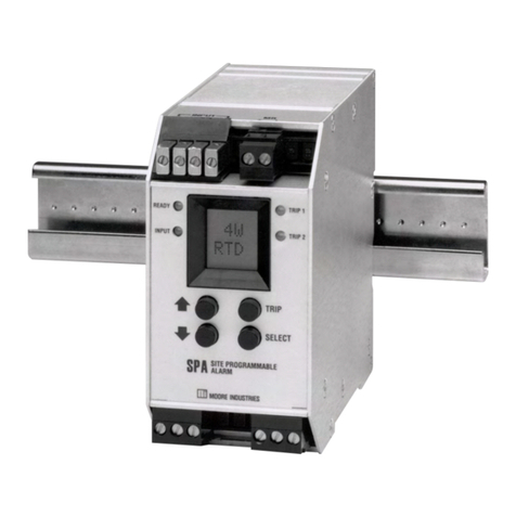
Moore Industries STA HLPRG User manual

225-748-01L
February 2017
User’s Manual
Demand Moore Reliability
STAHLPRG
www.miinet.com
STAHLPRG Programmable Current/Voltage Safety Trip Alarm
Programmable Current/Voltage
Safety Trip Alarm

www.miinet.com Moore Industries-International, Inc.
- 2 -
User’s Manual
225-748-01L
February 2017
Programmable Current/Voltage Safety Trip Alarm
STAHLPRG
Locations
Customer Support
Moore Industries is recognized as the industry leader in delivering top quality to its customers in products
and services. We perform a sequence of stringent quality assurance checks on every unit we ship. If any
Moore Industries product fails to perform up to rated specications, call us for help. Our highly skilled sta of
trained technicians and engineers pride themselves on their ability to provide timely, accurate, and practical
answers to your process instrumentation questions. Our headquarters and other facilities phone numbers
are listed below.
There are several pieces of information that can be gathered before you call the factory that will help our
sta get the answers you need in the shortest time possible. For fastest service, gather the complete model
and serial number(s) of the problem unit(s) and the job number of the original sale.
World Headquarters
16650 Schoenborn Street
North Hills, California
91343-6196, U.S.A.
Tel: (818) 894-7111
Fax: (818) 891-2816
E-mail: [email protected]
TOLL FREE: 1-800-999-2900
www.miinet.com
China
Room 806, Block 2,
Lotus International Plaza
No. 7866 Hu Min Road,
Min Hang District,
Shanghai, 201102, P. R. China
Tel: 86-21 62491499
Fax: 86-21 62490635
E-mail: [email protected]
www.miinet.com/cn
Europe
1 Lloyds Court, Manor Royal,
Crawley
W. Sussex RH10-9QU
United Kingdom
Tel: 01293 514488
Fax: 01293 536852
FREE PHONE: 0800 525107
www.miinet.com/uk
Guido Gezellestraat 106
B-2630 Aartselaar
Belgium
Tel: 03/448.10.18
Fax: 03/440.17.97
Dutch: www.miinet.com/dbe
French: www.miinet.com/fbe
Burg Meslaan 98
4003 CD Tiel
The Netherlands
Tel: (0)344-617971
Fax: (0)344-615920
www.miinet.com/nl
Australia
Sydney, NSW
3/1 Resolution Drive
Caringbah, New South Wales
2229
Australia
Tel: (02) 8536-7200
Fax: (02) 9525-7296
www.miinet.com/au
Perth, WA
6/46 Angove Street
North Perth, Western Australia
6006
Australia
Tel: (08) 9228-4435
Fax: (08) 9228-4436
www.miinet.com/au
www.miinet.com
Demand Moore Reliability

www.miinet.comMoore Industries-International, Inc. - 3 -
User’s Manual
225-748-01L
February 2017
Safety Messages
Please read this manual in its entirety. It should answer most of your questions. For personal and system safety, and for
optimum product performance, make sure you thoroughly understand the contents before installing, using, or maintaining
this product. Should you still have questions please visit our web site at
www.miinet.com or contact any of our sales/support oces nearest you.
Your safety and the safety of others is very important. We have provided many important safety messages in this
manual. Please read these messages carefully. These safety messages alert you to potential hazards that could hurt
you or others or render damage to units.
All Moore Industries instrumentation should only be used for the purpose and in the manner described in this manual.
If you use this product in a manner other than that for which it was intended, unpredictable behavior could ensue with
possible hazardous consequences.
Each safety message is associated with a safety alert symbol. These symbols are found in the throughout the manual.
The denition of these symbols is described below:
Pay particular attention wherever you see the following symbols:
Note – Information that is helpful for a procedure,
condition or operation of the unit.
Caution – Hazardous procedure or condition that
could damage or destroy the unit.
Warning – Hazardous procedure or condition that
could injure the operator.
Qualied Personnel
The Moore Industries’ product/systems described in this manual may be operated only by personnel qualied for the
specic task in accordance with the relevant documentation, in particular its warning notices and safety instructions.
Qualied personnel are those who, based on their training and experience, are capable of identifying risks and avoiding
potential hazards when working with these Moore Industries’ products/systems.
Proper use of Moore Industries products
Moore Industries’ products may only be used for the applications described in the catalog and in the relevant technical
documentation. If products and components from other manufacturers are used, these must be recommended or
approved by Moore Industries’. Proper transport, storage, installation, assembly, commissioning, operation and
maintenance are required to ensure that the products operate safely and without any problems. The permissible ambient
conditions must be complied with. The information in the relevant documentation must be observed.
We have reviewed the contents of this publication to ensure consistency with the hardware and/or software described.
Since variance cannot be precluded entirely, we cannot guarantee full consistency. However, the information in this
publication is reviewed regularly and any necessary corrections are included in subsequent editions. Specications and
information are subject to change without notice.
All product and company names are trademarks™ or registered® trademarks of their respective holders. Use of them
does not imply any aliation with or endorsement by them unless otherwise specied.
Programmable Current/Voltage Safety Trip Alarm
STAHLPRG
About this Manual
www.miinet.com Moore Industries-International, Inc.
- 4 -
User’s Manual
225-748-01L
February 2017
Table of Contents
STA (HLPRG) Quick Start Guide ..................................................................................................................... 5
Default/Factory Conguration 6
Section 1 - Introduction 7
Overview............................................................................................................................................................ 7
Description........................................................................................................................................................ 7
Model Numbers and Options........................................................................................................................... 8
Alarm Terminology ......................................................................................................................................... 10
Section 2 - Calibration and Bench Check 12
Calibration....................................................................................................................................................... 12
Bench Check................................................................................................................................................... 12
Section 3 - Installation and Wiring 15
Dimensions ..................................................................................................................................................... 15
Conditions of Use........................................................................................................................................... 16
Terminal Designations ................................................................................................................................... 17
Security Settings ............................................................................................................................................ 21
Section 4 - STA Front Panel Conguration 22
Section 5 - STA PC Conguration 45
Section 6 - Operation and Maintenance 60
Operation ....................................................................................................................................................... 60
STA Diagnostics & Fault Alarms ................................................................................................................... 60
STA Diagnostic Messages ............................................................................................................................. 61
Maintenance.................................................................................................................................................... 62
Section 7 - STA in Safety Instrumented Systems 63
Proof Tests .................................................................................................................................................... 67
Section 8 - Applications 69
High Integrity Alarm Trip................................................................................................................................ 69
High Availability Architecture........................................................................................................................ 69
1oo2 Redundant Architecture ....................................................................................................................... 70
Analog Output in the Safety Path ................................................................................................................. 71
High Integrity Analog Output ........................................................................................................................ 71
Section 9 - Specications 72
Section 10- Ordering Information 74
Warranty Disclaimer 76
Programmable Current/Voltage Safety Trip Alarm
STAHLPRG
CONTENTS

www.miinet.comMoore Industries-International, Inc. - 5 -
User’s Manual
225-748-01L
February 2017
STA (HLPRG) Quick Start Guide
Use the front pushbuttons to quickly and easily set-up the STA for your application. After
programming your alarm using the diagram below, install the unit into your application using the
connection diagrams and terminal designation table located in this manual.
The STA configuration can be recorded using the worksheet found at the end of this manual.
Please contact Moore Industries Sales for an interactive version of the worksheet.
Front Panel
Pushbuttons
Use the UP and DOWN pushbuttons to scroll through menus and
sub-menus. Use the SELECT pushbutton to access menus and/or
make a choice.
Tr im Analog Output:
Connect the STA into a calibration
set-up as shown in the manual,
trim the analog output
Set Tr im Zero, Full,
Factory Tr im and Test.
(Requires -AO Option)
Password:
View or change password.
Configure Options:
Display mode, decimal places,
50/60Hz filter, startup delay, display test
and factory reset.
CONFG
OPTNS
TRIM
AOUT
Reset Fault:
Reset fault option,
select “Yes” or “No”.
CONFG
PASWD
Exit Configuration Menu:
Return to process display.
CONFG
EXIT
D
D
U
CONFG
ALARM
Configure Alarm:
Settings for Alrm 1, Alrm 2, Input Fault*, and Manual Reset*.
Set trip point, dead band, high/low trip, latching/non-latching,
Enter Delay*, and Manual Reset Configuration*.
D
SCALE
AOUT
Scale Analog Output:
Set the values for output at
zero and full input
(Requires -AO Option)
D
U
RESET
FAULT
D
D
U
CONFG
AOUT
Configure Analog Output:
Select volt or current output.
Choose damping value
and fail mode.
(Requires -AO Option)
TRIM
INPUT
Tr im Input:
Select Tr im Mode, User 1 PNT,
User 2 PNT, or FCTRY TRIM
D
U
U
U
D
U
U
U
D
U
ENTER
PASS
SYS
LOCK
Enter the password
code to enable
settings changes.
(Default = 1)
(
If the incorrect password is entered,
access to the configuration menus is denied.)
Configure Input:
Choose Input type,
Input Zero, Input Full, Input OOR*,
and BWIRE Level
Security Jumper
installed in Full
Access position.
Security Jumper
installed in No
Access position.
Security Jumper
installed in Password
Required position.
CONFG
INPUT
SELECT
DOWN
UP
SCALE
INPUT
D
D
Scale Input:
Set the Scale Mode On/Off, set EGU, set Zero values,
and set Full values.
WARNING: This menu is intended to aid in the configuration of your instrument.
However, proper use of the STA at its intended safety level cannot be
achieved without thorough review of the STA in Safety Instrumented
Systems Section of this manual.
* For STA units with firmware versions 1.4 and earlier, these Settings are not configurable.
Programmable Current/Voltage Safety Trip Alarm
STAHLPRG
SECTION 1

www.miinet.com Moore Industries-International, Inc.
- 6 -
User’s Manual
225-748-01L
February 2017
Default/Factory Conguration
The following are the default factory settings for your unit.
Input: 4-20mA
*Lower Out of Range Value: 3.84 mA (1% of Span)
*Upper Out of Range Value: 20.16 mA (1% of Span)
*Startup Delay: 0 Seconds
Scale Mode: Off
Trim Mode: Factory Trim
Trip Alarms: Trip High at 12mA with Deadband set to 0
*Input Fault Alarm: Latching (On)
*Manual Reset: Trip Alarms 1 & 2 Only
Optional Analog Output (AO): Current, No Damping, Fail Low, Scaled to 4-20mA
Display: Process Variable (PV), Auto Decimal Point, 60Hz Filter
Broken Wire Detection: Level Set to 0 (disabled)
Password: 1
* For STA units with firmware versions 1.5 and earlier, these Settings are not configurable.
Programmable Current/Voltage Safety Trip Alarm
STAHLPRG
SECTION 1

www.miinet.comMoore Industries-International, Inc. - 7 -
User’s Manual
225-748-01L
February 2017 Programmable Current/Voltage Safety Trip Alarm
STAHLPRG
SECTION 1
Section 1 - Introduction
This is the user’s manual for Moore Industries’ STA (HLPRG): Programmable Current/Voltage
Safety Trip Alarm.
The Moore Industries’ Safety Trip Alarm (STA) is designed and manufactured to provide a high
level of availability for safety critical applications and for use as a component part of a safety
instrumented system.
Overview
This manual contains all of the information needed to configure, install, operate and maintain this
product. When the STA is used in a SIL rated safety application (as defined by IEC 61508), the
Safety Instrumented Systems section of this manual must be read and followed in order for the
STA to meet its IEC 61508 certification requirements.
Description
Moore Industries’ STA (HLPRG) is a Programmable Current/Voltage Safety Trip Alarm.
The STA monitors a process variable and provides two fully user-configurable contact closure
outputs that can be individually programmed to trip whenever the input falls outside a user-set,
high or low trip point. It also has one fault alarm output which is triggered by a self-diagnosed
failure of the input or the STA itself. The STA is typically used to activate a warning light, bell
or buzzer; or to initiate a system shutdown. Thus, the instrument acts as a simple, but highly
reliable and effective means of monitoring and safe-guarding a process.
The STA may be configured using front panel push buttons and/or Moore Industries’ PC
Configuration Software. A large 5-digit display shows menu prompts during push button
configuration and process variable and status messages during normal operation.
The STA also has a password security feature to limit access to the front panel configuration.
Refer to Security Settings in the Installation and Wiring Section for more details.
All STA diagnostic faults are latching and input faults can be configured to latch or not latch.
User configuration faults will clear automatically once the configuration is valid. If input faults are
latched, these can be cleared by the “RESET FAULT” menu and the Manual Reset (MR) terminal
can also be configured to reset both latched Trip Alarms and input faults. Unit faults such as
internal diagnostics will always latch the Fault Alarm and the unit must be power cycled to clear
the alarm.
Note: For STA units with firmware versions 1.5 and earlier, the fault alarm has no configuration
options, is always latched and cannot be reset by Manual Reset (MR).

www.miinet.com Moore Industries-International, Inc.
- 8 -
User’s Manual
225-748-01L
February 2017
Programmable Current/Voltage Safety Trip Alarm
STAHLPRG
SECTION 1
Model Numbers and Options
The following section provides details of the Moore Industries model number and the available
options for the STA.
Moore Industries model numbers for STA are structured as follows:
STA / HLPRG / 3PRG / U / -AO [DIN]
Unit / Input / Output / Power / -Options [Housing]
Refer to Section 10 Ordering Information for a quick reference table of ordering information
INPUT
HLPRG
The STA (HLPRG) supports either current inputs from 0-50mA (4mA minimum span) or
voltage inputs from 0-11V (1V minimum span). These inputs can be trimmed and scaled,
refer to the Conguring Inputs section of this manual for additional information.
OUTPUT
3PRG
The STA has three programmable contact closure alarms. One relay is factory configured
as a Fault alarm and the remaining two relays are user-configurable Trip alarms. A dual
color LED (Red/Green) is provided with each alarm to indicate its condition.
The fault alarm trips on a self-diagnosed failure within the STA or on any of its inputs.
This alarm is latching and has to be reset by the user. Only user configuration faults will
clear automatically once the configuration is valid. Input faults can be configured to Latch
or not Latch and can be cleared by the “RESET FAULT” menu or by the MR terminals if
configured to reset both latched Tripped Alarms or input faults. Self-Diagnosed unit faults
can only be cleared by power cycling the unit.
Note: For STA units with firmware versions 1.5 and earlier, the fault alarm has no configuration
options, is always latched and cannot be reset by Manual Reset (MR).
For more information refer to the Diagnostics and Fault Alarm section.
The Trip alarms are configurable for high or low trip with an adjustable dead band. These
alarms can be latching or non-latching. Latched alarms are reset through the Manual
Reset (MR) terminals.
The relay outputs have a 3A@250Vac or 3A@30Vdc, 50/60Hz non-inductive contact
rating. The contact arrangement is SPDT (1FormC). All outputs are fail safe and will
deenergize to trip (DET) with normally open (NO) and normally closed (NC) relay contacts.
Refer to the Alarm Terminology and Configuring the Alarms sections of this manual for
additional information.

www.miinet.comMoore Industries-International, Inc. - 9 -
User’s Manual
225-748-01L
February 2017 Programmable Current/Voltage Safety Trip Alarm
STAHLPRG
SECTION 1
POWER
U
Accepts any power input range between 21.6-375Vdc or 90-260Vac. Power consumption
is 5W maximum.
24DC*
This option instrument requires power is 24Vdc, ±25%. Power consumption is 3.5W
maximum.
UAC*
Accepts any power input range between 90-260Vac. Power consumption is 4W maximum.
*Power supply option no longer available for purchase.
OPTIONS
-AO
If your STA has the Analog Output option, Analog Output can be configured to provide
a voltage (0-10V) or current (0-20mA) output. The current output can be sink or
source. Refer to the Configuring the Analog Output section of this manual for additional
information.
Note: For units with firmware V1.2 or earlier, the Analog Output cannot be used as part of the
safety path.
HOUSING
[DIN]
DIN-style housing mounts on a 35mm Top Hat rail (EN50022)
[FLB]
Flange bracket provides a secure mount for high vibration applications.

www.miinet.com Moore Industries-International, Inc.
- 10 -
User’s Manual
225-748-01L
February 2017
Programmable Current/Voltage Safety Trip Alarm
STAHLPRG
SECTION 1
Figure 1.1. How Alarms Work with the Process Input
HIGH ALARM
TRIP POINT
LOW ALARM
TRIP POINT
DEADBAND
RESET
DEADBAND
RESET
IN ALARM
IN NON-ALARM
TIME
The Trip Point is the process input level at which the user wants an alarm relay to change state,
typically going into an alarm condition, or “tripping”. In the STA, the user sets the trip point for
each alarm relay.
High/Low Alarms; High Alarms trip when the process input goes above the trip point. Low
Alarms trip when the process input drops below the trip point. Each of the STA relay outputs can
be set by the user to function independently as either high or low alarms.
Latching and Non-latching Alarms; once tripped, a latching alarm remains in an alarm state
until the input returns to a non-alarm level AND is manually reset. Non-latching alarms return to
a non-alarm state whenever the process input returns to the Reset Point. The STA relays can be
set by the user to function as either latching or non-latching.
The Reset Point is the process input level at which the user wants an alarm relay to change
state, typically going from alarm to non-alarm. The reset point is not necessarily the same as the
trip point, because most applications call for a buer zone or deadband around the trip point to
allow for minute uctuations in the process input. In the STA, the reset point is determined by the
deadband setting. Latching STA alarms will not “clear” unless the reset point has been reached
or passed AND the manual reset contacts have been shorted.
The deadband is the range in which an alarm remains tripped even after the process input has
returned to or passed the trip point. Deadband is not required. When it is not incorporated into a
non-alarm application, the trip point and reset point are the same. The deadband of the STA is
set by the user.
Alarm Terminology
Before setting up the STA, or incorporating the unit in your application, Moore Industries
suggests that all users take a few moments to become familiar with some of the terms
associated with the use of process instrumentation alarms.

www.miinet.comMoore Industries-International, Inc. - 11 -
User’s Manual
225-748-01L
February 2017 Programmable Current/Voltage Safety Trip Alarm
STAHLPRG
SECTION 1
Failsafe Alarms are de-energized when tripped, energized when the process input is at a
non-alarm level. Non-failsafe alarms are energized whenever tripped, de-energized when the
process input is at a non-alarm level. The relays in the STA are failsafe only. Normal is the term
used to describe the “shelf-state” of relay contacts. The contacts of a Normally Open relay are
open (innite resistance) when the relay is not energized. The contacts of a Normally Closed
relay are open when the relay is energized (closed when not energized).
Note: Sometimes a non-alarm input level is referred to as being in a “normal” condition. This
practice is intentionally avoided in this manual. Do not confuse the term “normal”, as in Normally
Open or Normally Closed, with a non-alarm input condition. In this manual, “normal” is an
exclusive reference to the shelf state or quiescent state of an alarm’s relay contacts, whether
open or closed.

www.miinet.com Moore Industries-International, Inc.
- 12 -
User’s Manual
225-748-01L
February 2017
Moore industries-International, Inc.
Section 2 - Calibration and Bench Check
It is recommended that you perform a bench check on your instruments prior to installing them in
your application.
Calibration
A true calibration of the STA can only be performed at Moore Industries using specialized
equipment. We recommend that you check the calibration every year and re-calibrate only when
necessary.
However, input trimming increases the measurement accuracy of your instrument by matching
the reading of its actual input to its scaling. The STA oers the use of a factory-congured
trimming feature (‘FCTRY TRIM”) or user-set, one-point or two-point (“USER 1 PNT” or “USER 2
PNT”) trimming.
Please refer to Section 4 of this manual for instructions to perform Input Trimming via Push
button panel or Section 5 using the PC Conguration Software.
Likewise, output trimming increases the measurement accuracy of the STA by calibrating its
Analog Output to the device that is receiving the output. This ensures that the instrument is being
correctly interpreted.
Please refer to Section 4 of this manual for instructions to perform Output Trimming via Push
button panel or Section 5 using the PC Conguration Software.
Bench Check
We highly recommend that you perform a bench check of your STA prior to installing it in the
eld. This will ensure that the STA is operating within your expectations or requirements.
The bench check is a quick way to determine that your STA is functioning as expected.
Depending on your organization’s requirements, you may also be required to perform a complete
Proof Test on your STA. The instructions for the Proof Test can be found in Section 7 of this
manual.
As a prelude to performing the bench check you should congure your STA as it is to be used
in your nal application. Refer to Section 4 for the STA Front Panel Conguration instructions.
These instructions are used if you are conguring your STA by using the front panel push
buttons. Section 5 contains the instructions for conguring your STA using the STA PC
Conguration software.
The equipment necessary to perform a bench check can be found in Table 2.1.
Programmable Current/Voltage Safety Trip Alarm
STAHLPRG
SECTION 2
Table 2.1. Necessary Equipment for Bench Checking the STA (HLPRG)
Device Specifications
Power Supply
Multimeter
U: 21.6 - 375 Vdc or 90-260Vac; 24DC:18-30Vdc; UAC: 90-260Vac
Accurate to ±0.009% of span; e.g., HP Model 3478A
Current and/or Voltage Source Variable; accurate to ±0.05% of unit span

www.miinet.comMoore Industries-International, Inc. - 13 -
User’s Manual
225-748-01L
February 2017
Bench Check Procedure
1. Current or Voltage Input:
In order to provide an input to your STA HLPRG you will need to use an appropriate input
source. By example – if you plan to use your STA with a current (mA) input you will need
to use a milliamp source to provide the appropriate input during your bench check. The
same goes for a voltage source. Use whichever input source is correct for your intended
application. Please see Figure 2.1 for the correct input connections.
Programmable Current/Voltage Safety Trip Alarm
STAHLPRG
SECTION 2
Figure 2.1. STA (HLPRG) Hook-Up Diagram
CURRENT
SOURCE
_
+
SELECT
DOWN
UP
COM
READY INPUTTRIP 1TRIP 2 FAULT
STA
SAFETY
TRIP
ALARM
TAG
2-WIRE
TRANSMITTER
( Output Loop
Powered Device)
_
+
SELECT
DOWN
UP
COM
READY INPUTTRIP 1TRIP 2 FAULT
STA
SAFETY
TRIP
ALARM
TAG
VOLTAGE
SOURCE
_
+
SELECT
DOWN
UP
COM
AC OR DC
POWER
SUPPLY
GND
-
+
AC OR DC
POWER
SUPPLY
GND
-
+
AC OR DC
POWER
SUPPLY
GND
-
+
READY INPUTTRIP 1TRIP 2 FAULT
STA
SAFETY
TRIP
ALARM
TAG

www.miinet.com Moore Industries-International, Inc.
- 14 -
User’s Manual
225-748-01L
February 2017
Moore industries-International, Inc.
2. Power Input:
Connect the appropriate power source as shown in Figure 2.1.
3. Set your input source to the low end of your congured input span. By example – if your
input is congured for a current (mA) and your input range is set for 4-20mA then use a
current source and set it to 4mA. Verify that the STA is reading 4mA on its display window.
4. Set your input source to the high end of your congured input span and verify that the STA’s
display window correctly reects the input.
5. Set your input source to a value higher or lower than your congured input span and verify
that the Fault Relay changes state. The Fault Relay can be reset via the front panel push
buttons or via MR terminals (if congured).
6. Temporarily remove one of your input connections to verify that the Broken Wire feature
is working. Note: the Fault Relay can be reset via the front panel push buttons or via MR
terminals (if congured).
7. Alarm Relays:
By adjusting your input up and down you can conrm the operation of the Alarm Relays.
Use your multimeter (set to ohms) to verify the state of the relay contacts.
Units with the Analog Output option (-AO)
The STA’s analog output can be user congured one of three ways – 1) 0-20mA sourced with
voltage sourced by the STA (also referred to as Io Source) or 2) 0-20mA with voltage sourced by
the DCS (also referred to as Io Sink) or 3) 0-10V (also referred to as Vo).
Note that even though 0-20mA is the range of the analog output it can be scaled by the user for a
narrower range (such as 4-20mA). The same goes for the voltage output.
1. Connect the analog output as per Figure 3.3. Use the terminals that are correct for your
application.
2. When testing the milliamp output it is best to use a 250 ohm precision resistor across the
output terminals (as shown in Figure 3.3). Then you can use your multimeter (set to voltage)
to read the voltage drop across the resistor. Hence a reading of 1V means that the analog
output is putting out 4mA, and a reading of 5V equates to a 20mA output. If using the STAs
voltage output terminals (+/-Vo) the voltage can be read directly with your multimeter.
3. Set your input simulator to the low end of your congured input span. Verify that the analog
output is correct. By example – a 1V reading across your 250 ohm resistor equates to a
4mA output.
4. Set your input simulator to the high end of your congured input span. Verify that the analog
output is correct. By example – a 5V reading across your 250 ohm resistor equates to a
20mA output.
You have now conrmed that your STA is operating correctly and can now be condently
installed into your application.
Programmable Current/Voltage Safety Trip Alarm
STAHLPRG
SECTION 2

www.miinet.comMoore Industries-International, Inc. - 15 -
User’s Manual
225-748-01L
February 2017
Section 3 - Installation and Wiring
Instructions in this section and others may require special precautions to ensure the safety of the
personnel performing the operations. Notes, Cautions and Warnings that may cause potential
safety issues are indicated throughout this manual by symbols, please refer to Page 3 of this
manual for the denitions of these safety message symbols.
Note: Make sure to calibrate and bench check the instruments prior to installation. Also,
install all instruments in their intended application and on their rail before making any electrical
connections. Allow enough room for pivoting instruments vertically on the rail for removal in
applications involving multiple banks of STAs.
Note: Any changes to Security Settings will need to be made prior to installation and wiring refer
the Security Settings Section in this section.
Dimensions
Figure 3.1. Dimensions of STA HLPRG
102mm
(4.0 in)
56mm
(2.2 in)
142mm
(5.6 in)
17.29
MA
Programmable Current/Voltage Safety Trip Alarm
STAHLPRG
SECTION 3

www.miinet.com Moore Industries-International, Inc.
- 16 -
User’s Manual
225-748-01L
February 2017
Figure 3.2. FLB flange bracket dimensions.
Mounting
The STA is housed in a DIN case that can be mounted on 35mm Top-Hat (EN50022) DIN-rail. To
mount the STA on a Top-Hat DIN-rail, seat the upper extrusion on the unit back panel over the top
lip of the rail and pivot downward until the housing locks into place. When mounting multiple units,
like a rack or cabinet, make sure to allow adequate vertical spacing for pivoting the units.
A ange bracket option is also provided as a secure mount for high vibration applications.
Reference gure 3.2 below.
Removal
To remove the STA from DIN rail you will need a simple tool such as a straight blade screwdriver.
Insert the blade of the screwdriver into cavity at the bottom of the locking mechanism and rotate
it. This will release the locking mechanism from DIN rail and allow you to remove the STA.
Special Conditions of Use
The following instructions must be adhered to when the STA is used in hazardous locations and
potentially explosive atmospheres.
Note: The STA shall be installed in compliance with the enclosure, mounting, spacing and
segregation requirements of the ultimate application. Electronic components must be mounted in
a suitable enclosure.
23mm
(0.9 in)
18mm
(0.7 in)
9mm
(0.4 in)
2 mm
(0.1 in)
11mm
(0.4 in)
143mm
(5.6 in)
121mm
(4.8in)
Ø6mm
(Ø0.3 in)
Programmable Current/Voltage Safety Trip Alarm
STAHLPRG
SECTION 3

www.miinet.comMoore Industries-International, Inc. - 17 -
User’s Manual
225-748-01L
February 2017
Figure 3.3. Terminal Designations
Terminal Designations
1234
MR
TX
+ I
COM
+ V
MR
NO1
CM1
NC1
NO2
CM2
NC2
AC/DC
ACC/DCC
GND
NO3
NOT
USED
CM3
NC3
RELAY 1 RELAY 2
INPUT
FAULT
RELAY
CONTACTS
FAULT
RELAY
CONTACTS
3PRG
4-20mA Output Loop
Voltage sourced by DCS
4-20mA Output Loop
Voltage sourced by STA
Voltage Signal
Output from STA
WITH -AO
OPTION
-AO OPTION
OUTPUTS
1234
MR
MR
+Io
Source
-Io Source
+Io Sink
+Vo
-Vo
-Io Sink
NO1
CM1
NC1
NO2
CM2
NC2
AC/DC
ACC/DCC
GND
NO3
NOT
USED
CM3
NC3
RELAY 1RELAY 2
INPUT
TX
+ I
COM
+ V
3PRG -AO
OUTPUT
TRIP RELAY CONTACTS
+Io Sink
+Io Source
-Io Source
-Io Sink
+Vo
+V
-Vo
A OUT
MR
DCS
or
PLC
+Io Sink
++
--
+
-
+Io Source
-Io Source
-Io Sink
+Vo
-Vo
A OUT
MR
DCS
or
PLC
DCS
or
PLC
+Io Sink
+Io Source
-Io Source
-Io Sink
+Vo
-Vo
A OUT
MR
INPUT
TX
COM
V
INPUT
TX
COM
V
INPUT
TX
COM
V
TRIP RELAY CONTACTS
NOTES:
1. Terminal blocks can accommodate 14-22 AWG solid
wiring.
2. ±Io/±Vo labeling is present only when the unit is equipped
with the Analog Output (-AO) option.
3. Your input power requirement (AC or DC / ACC or DCC).
KEY:
AC or DC = Power Input
ACC or DCC = Power Input
CM = Relay Common
GND = Ground
Io = Current Output
MR = Manual Reset
NO = Normally Open
NC = Normally Closed
Sink = Current Sink
Source = Current Source
SPDT = Single-Pole/Double-Throw
Vo = Voltage Output
Programmable Current/Voltage Safety Trip Alarm
STAHLPRG
SECTION 3
Electrical Connections
Refer to Figure 3.4 for electrical connections.
When installing any Moore Industries product, always follow all local regulations and standards
for grounding, shielding, and safety.
Warning: Terminals on this unit may be connected to hazardous voltages. Before making ANY
connections to this unit, always remove power from the loop or instrument power terminals.
Installation Category
All terminals are rated CAT I.

www.miinet.com Moore Industries-International, Inc.
- 18 -
User’s Manual
225-748-01L
February 2017
Programmable Current/Voltage Safety Trip Alarm
STAHLPRG
SECTION 3
Figure 3.4. STA (HLPRG) Hook-Up Diagram
CURRENT
SOURCE
_
+
SELECT
DOWN
UP
COM
READY INPUT TRIP 1 TRIP 2 FAULT
STA
SAFETY
TRIP
ALARM
TAG
2-WIRE
TRANSMITTER
( Output Loop
Powered Device)
_
+
SELECT
DOWN
UP
COM
READY INPUT TRIP 1TRIP 2 FAULT
STA
SAFETY
TRIP
ALARM
TAG
VOLTAGE
SOURCE
_
+
SELECT
DOWN
UP
COM
AC OR DC
POWER
SUPPLY
GND
-
+
AC OR DC
POWER
SUPPLY
GND
-
+
AC OR DC
POWER
SUPPLY
GND
-
+
READY INPUT TRIP 1 TRIP 2 FAULT
STA
SAFETY
TRIP
ALARM
TAG

www.miinet.comMoore Industries-International, Inc. - 19 -
User’s Manual
225-748-01L
February 2017 Programmable Current/Voltage Safety Trip Alarm
STAHLPRG
SECTION 3
Equipment Ratings
Contact Relays
The STA does not generate hazardous voltages but can switch outputs up to 3A at up
to 250Vac or 30Vdc on its relay contacts. Products connected to the STA should be
designed to receive this type of input.
Analog Output
The STA does not generate hazardous voltages, it provides a low current (4-20mA) or
voltage (1-5V) input and a 4-20mA output. Products connected to the STA should be
designed to receive this type of input.
Warning: If this unit is used in a manner not specified by Moore Industries, the protection
provided by the equipment may be impaired.
Switches and Circuit Breakers
For STA AC powered units, a switch or circuit breaker must be wired in series with the AC power
conductors. The switch or circuit breaker used must be located within three meters of the unit.
The circuit breaker or switch will only remove power to the unit; hazardous voltages may still be
connected to other terminals on the unit.
Power Supply Wiring
All power connections should be made with 14 or 16 AWG (2mm2or 1.3mm2) wire.
The end of each conductor should be stripped no more than 0.25in (7mm). The end of the
stripped wire should be tinned with solder, or inserted into a ferrule and crimped before being
placed into a terminal block.
Tighten the screws on the terminal block to 4.4 - 5.3 lbf/in2(0.5 - 0.6 N/m2).
Protective Earth Conductor
The Protective Earth Conductor shall be of equal or larger size wire than the other two power
conductors. The Protective Earth Conductor shall be the first conductor connected to the unit
when the unit is being wired. It shall be the last conductor removed when the unit is being
un-wired.
Input/Output Wiring
The Input/Output connections can be made with 14 to 24 AWG (2.5mm2 to 0.2mm2) wire. The
end of each conductor should be stripped no more than 0.25in (7mm). Tighten the screws on the
terminal block to 4.4 - 5.3 lbf/in2(0.5 - 0.6 N/m2).

www.miinet.com Moore Industries-International, Inc.
- 20 -
User’s Manual
225-748-01L
February 2017
Programmable Current/Voltage Safety Trip Alarm
STAHLPRG
SECTION 3
Recommended Ground Wiring Practices
Moore Industries recommends the following ground wiring practices:
• Any Moore Industries product in a metal case or housing should be grounded.
• The protective earth conductor must be connected to a system safety earth ground before
making other connections.
• All input signals to, and output signals from, Moore Industries’ products should be wired
using a shielded, twisted pair wiring technique. Shields should be connected to an earth or
safety ground.
• For the best shielding, the shield should be run all the way from the signal source to the
receiving device. (see Note below)
• The maximum length of un-shielded input and output signal wiring should be 2 inches.
Note: Some of Moore Industries’ instruments can be classified as receivers (IPT2, IPX2, etc.)
and some can be classified as transmitters (TRX, TRY, etc.) while some are both a receiver and
a transmitter (SPA2, HIM, etc.). Hence, your shield ground connections should be appropriate for
the type of signal line being shielded. The shield should be grounded at the receiver and not at
the signal source.
CE Certification-related Guidelines
Installation of any Moore Industries’ products that carry the CE marking must adhere to the
guidelines in the Recommended Ground Wiring Practices section in order to meet the EN 61326
requirements set forth in the applicable EMC directive.
The Low Voltage Directive also applies to the AC powered versions of the STA and/or when
connecting any of its output relay contacts to voltages greater than 50 vac. In order to comply
with EN61010-1 (Low Voltage Directive) all guidelines in this section must be followed.
Contact/Load Suppression
When the instrument relays are used to switch an inductive load such as an external relay coil,
contactor, solenoid, large voltage spikes may be created in nearby cable harnesses. When
excessive, these voltage spikes can disrupt the operation of all nearby electronics including this
product. Inductive loads should have suppression devices installed at the load (for external
relays this would be right across the relay coil itself). Usually this is a simple diode for dc
circuits. AC circuits routinely use an R-C snubber. Please follow the external load manufacturer
instructions for their recommended suppression kits.
Table of contents
Other Moore Industries Security System manuals

Moore Industries
Moore Industries SPA TPRG User manual

Moore Industries
Moore Industries DDA Series User manual

Moore Industries
Moore Industries SPA2 TPRG User manual

Moore Industries
Moore Industries CPA User manual

Moore Industries
Moore Industries DCA S User manual

Moore Industries
Moore Industries SPA HLPRG User manual

Moore Industries
Moore Industries SPA User manual