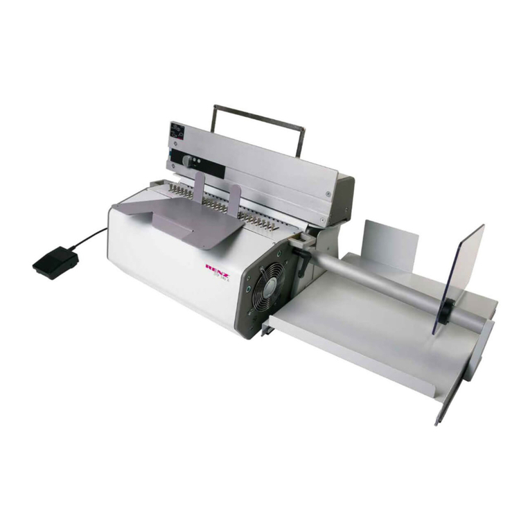
Morgana KB2000 User manual

Morgana Systems Limited ▪ United Kingdom ▪ www.morgana.co.uk ▪ Telephone: ( 01908 ) 608888 ▪ Facsimile: ( 01908 ) 692399
KB2000/KB2000S
OPERATOR MANUAL

Operator Instruction Manual
FKS PrintBind KB 2000
Perfect Binder
Glue-Binding-Machine
for
Hot-Melt-
A
dhesive:
Cover-Binding
Padding
C
Issue: 2004 (No:4011120)
(from machine serial number: 0061510411110 upwards)

Please Note:
For any more questions than answered in this manual:
Please contact your supplier.
For clear description and identification of item:
Please name the Section (10 Sections are available) and
please name the paragraph of Section in mind as well.

Sections of this manual:
1. General Information
2. Installation
3. Components & Features
4. Name of each part of machine
. Function of each part.
5. How to handle binding
6. Set up of functions
7. Air-Compressor
8. Accessories
9. Technical Specifications
10. Stand Cabinet (Installation)

Important
1.General Information
Air-Compressor (pump)
The air-compressor (pump with tank) must always be in upright position.
After unpacking, the pump has to be placed in upright position for 30
minutes before switching on! This allows the oil in pump to move in place.
In case pump had been transported and you are not sure about it`s upright
position in transit: Let have rest the pump in upright position for 30 minutes.
During de-installation of pump – prior to any transport - please seal inlets
and outlest of pump with caps. Please follow: Section 7 Air-Compressor in
this manual carefully!
Positioning of FKS PrintBind KB 2000
Place the FKS PrintBind KB 2000 on perfect horizontal level.
In case the FKS stand-cabinet (on rolls) is part of the delivery:
Take care that the stand-Cabinet is positioned on horizontal level as well.
Please follow Section 2. Installation
Warm-Up time of glue
Take in account that it must be allowed to wait 30 to 40 minutes after
switching on the machine to melt the glue up to desired temperature prior
to first binding.
For limited interruption whilst binding a stand-by position can be selected.
(Please follow section 4 and 5.)

2.Installation
Installation of Stand cabinet
The version: “Complete Mounted” please unpack.
It is ready for use.
The version: ”Dismantled to be mounted” …
please unpack and follow the assembly instructions.
These are described on last page of this instruction book.
An assembly instruction can be found in the box of stand cabinet as well.
Installation of: Air-Compressor
Please see important notes in session 1. General Information
and in session 7. Air-Compressor.
Installation of FKS PrintBind KB 2000
Please note session 1. General Information and the following:
Unpack machine, air-compressor and accessory-package.
Place machine on horizontal level / on stand cabinet
Take off transport seals and locking.
Check all components for complete availability.
Follow instruction to assemble, mount, set and adjust in acc. to this
instruction book.

3. Components & Features
1) This perfect binder FKS PrintBind KB 2000 is designed for professional binding results with hot
melt adhesive. The layout of the main components and features are based on professional
standards and state of the art technology.
Special features incorporate unique functions as like as the spine preparation for better glue
penetration into set of papers.
The extremely strong pneumatic operated clamping for paper-set and cover-binding creates perfect
binding results.
Pre-scoring of cover-sheets only is recommended for the upper level of card board qualities.
The heavy duty construction led to a sturdy layout of the machine for constant use and long life time.
The automated operation procedure guarantees equal steps of finishing binding for binding.
The human operator only has to take care for correct loading of papers to be bound and cover to be
positioned in cover-station.
2) The operation procedure concentrates on pushing buttons for simplicity of use.
3) The unique spine preparation consists of a most modern designed Slitting Device in combination
with a Fanning Device which slightly fans the spine (The Fanning Device is not designed for
scuffing the spine!) prior to glue attachment.
4) After clamping the set of papers to be bound in right hand positioned clamp device, the whole
process of binding incorporates the spine preparation, glue attachment and cover clamping onto the
book in one step of operation by simply touch the start-button..
5) This “One-Touch-Operation” enables one operator to achieve up to 320 bindings per hour.
6) Various safety features, devices and functions prevent failures in binding and make sure a high
level of safety to the operator.
Safety hood
for coverage of hot glue-assy area and spine
preparation device.
By lifting up the Safety Hood the clamp action stops
and main drive is out of action..
The glue remains it´s temperature.
If required the paper can be removed from clamp by
touch button on main panel and as well the clamp will
return to home position.
Emergency Stop
To be used in case of any kind of accident. Main
drive will be disengaged.
Further procedure as per description for Safety Hood.
Reset by turning the red head on knob.

Paper Sensor in clamp assy
In paper clamp station prevents clamping
without paper to be bound positioned
between the clamps. Place paper to be
bound close onto back side of clamp.
Keep the sensor clean from paper dust.
Clamp Opening Stop...
…is factory-set to widest position. In case
of serial binding procedure of books with
substantial smaller spine it is
recommended to set the bolt in front more
close to minimize the opening of clamp. A
hexagon screw is fixing the bolt. (A driver is
included in accessory package).
Limiting the clamp opening in acc.to spine
of books enables the operator for easier
loading of paper-sets into clamp assy.
Cover for Slitting/Fanning Device
Is covered by a sliding coverage whilst clamp
is in right position. It opens whilst clamp is
moving across and it closed shortly after by
pass of clamp. It only is allowed to disengage
cover-system by authorized service.
The cover system prevents accidents for
operator.
O
p
en Closed
7) Taking in account and make use of all safety devices it is possible to change the glue.
The reason might be the choice of another type of glue. Never mix up different types of glue!
The factory filled glue can be ordered from supplier.
In case of a wrong set up of temperature for the type of glue in tank the glue might “burn out”.
After very long time of heating without using glue for binding the glue might be overheated.
In both cases the glue must be changed. (Glue only can be changed in melted condition!)
Outlet of Glue-Tank
Place card board box under shut
of outlet. (Steel can might become
hot – plastic can might melt!)
A 10 mm hexagon screw driver is
supplied with the accessory
package for opening the outlet
lock screw.
Release melted glue in card board box.
( Not included in accessory-package.( Use any one.)
Slitting/Fanning-Device is designed that only the upstanding 2 knifes are slitting and bending
the edge of slit! The “round type of saw “must never touch the spine of book!!! The setting is
exactly of level spine for fanning the edges of paper! Function is not scuffing at all!

4. Name of each part of machine
Function of each part.
1. Main Body and sections
Cover Station Glue Station Slitting/Fanning Station Clamp in loading position
Book Thickness Wheel Operator Main Panel
Main Switch
2. Main Switch (panel )
(Positioned on right hand side of machine)
Main Power Supply Switch ON - OFF
Main Fuse (Automatic/Resettable)
Check fuse whilst main power switch
is in OFF position
Slitting/Fanning-Assy-Switch ON - OFF

3. Paper- Clamp-Assy
(In ground position in right hand side location)
Paper Clamp Assy
Back Clamp (bears paper sensor)
Front Clamp
(moves by pneumatic action)
¨
4. Paper- Sensor in Clamp-Assy
Control: Paper loaded – none loaded.
Clamping and start moving of Clamp Assy possible only if paper is loaded.
Back Clamp
Paper Sensor on Back Clamp
Front Clamp (moves for clamping)

5. Cover Positioning Side-Guides
(Position of Guides can be adjusted in correct manner if desired.)
Cover Side Guide assy´s (2)
(Adjustable if not in correct position)
The cover has to be placed with it`s right hand long
edge against these guides in order to meet the
bound paper-set to be covered in right angle.
¨
6. Cover Top Positioning Guide Assy
(Position of Stop is related to size of cover)
Cover Top Positioning Guide Assy
(to be hooked on whilst installation. It is a content in
the accessory package)
Thump screw for positioning the top cover stop.
7. Cover Sensor
Cover Sensor
This Cover Sensor must be covered by cover-sheet
for binding.
If not covered, the machine will not start clamp
moving for binding.
Optional:
If the padding option is installed a Protection-
Film has to be positioned instead of a cover sheet.
In padding action the cover clamp-device is
disengaged. The Protection-Film simulates a cover
for the sensor and is a protection for the surface of
cover-device. In case by failure a none-cover-book
is released too early off clamp and might touch with
spine the surface of cover device.

8. Book/Cover Thickness Control
(Adjusting the height position of Cover-Clamp)
Control for individual adjustment in
respect to thickness of book and/or
thickness of cover-sheet-material.
Average book thickness to be
bound:
90 = app. 1 cm thickness of spine of book
20 = app 3 cm thickness of spine of book
Numbers on scale on Handwheel
Book (Spine) Thickness
Handwheel to be turned to left = UP = thin
book or turned to right = DOWN = thick
book.
Cover-Sheet Thickness
Handwheel to be turned to left = UP = light
weight cover sheet or turned to right =
DOWN = heavy weight of cover sheet
¨
Example: Handwheel: Down
Result of adjustment
Thick layer of glue on spine
Remaining glue is slightly pressed
sidewise and up between cover and
fonr/back sheets!
Example: Handwheel: UP
Result of adjustment:
Thin layer of glue on spine.
Remaining glue is slightly pressed
sidewise and up between cover and
fonr/back sheets!

9. Main Operating Panel
(Control board for binding)
Reset = All clear
Stand By = SB
Cover clamp: UP = V3
Cover-side-clamp: Close =V-2
UP-Set-Button
DOWN-Set-Button
Display
Ready lamp for START
Heating-up –
HEATER-LAMP
Clamp paper in
Clamp-assy
START-Button
Clamp to left = V-2
Clamp to right = V-3
Rotating: Glue rollers
Set Switch for MODE
Panel-Indications are shown on next pages:

9.1. Main Operating Panel
(Control board for binding)
Main Operating Panel located right hand on front of
machine.
Buttons and signal-lights (LED)
Numbers indicate function
Start Button
In case all other functions are set it is possible to
start machine with this button straight after
loading cover and paper.. 1
Clamp Button
Clamps loaded paper in clamp assy. In case
paper had been clamped press again for release.
2
Time-Down-Button for:
Temperatur-Set: DOWN
Paper- + Cover – Clamping= DOWN =
for clamping cover and brochure
(Depends on selection of function) 5
Time-Up-Button for:
Temperatur-Set: UP
Paper- and Cover-Clamping = UP
=for clamping cover and brochure
(Depends on selection of mode/ function ) 4
Start Indicator Lamp (LED)
Lightens green : ready to start binding.
3

9.2. Main Operating Panel
(Control board for binding)
Heater Lamp
Indicates that glue heating is in ON position
6
Reset (All Clear) Button
All (pneumatic) clamping actions for paper and
cover-device opens.
Counter sets to “0” 7
Stand-By-Button (Switch)
First press = glue temperature in stand-by
Second press = stand by released to normal
Stand-by temperature = 130 degree
8
Button for: Cover clamp up
In cover station the cover press-plate moves
up.
9
Button for: Cover side clamp close
In cover station the cover side-pressing plates
move onto cover/book.
10

9.3. Main Operating Panel
(Control board for binding)
Button: Clamp assy move left
As long as pressed the cpl clamp assy moves
in right hand direction.i
11
Button: Clamp assy move right
As long as pressed the cpl. clamp assy moves
in right hand direction.
7
Button: Manual rotating of glue rollers
As soon as temperature raised up to 130
degree this button allows to start rollers to
rotate frequently until the set temperature is
reached. 13
Set Switch for modes
The display shows: SET TEMP.
First press: Display changes to VICE 2
= cover-station.
Now the clamping- and pressing-time in cover
station can be adjusted for long or short time
by selection of 16 steps from 0 to 15. 14
Display: LCD
Shows different modes:
BLOCK TEMP = Temperature of glue tank
SET TEMP = desired temperature
COUNT = Counter
VICE 2 = Cover station assy
15

5. How to prepare for Binding
Generals
FKS PrintBind KB 2000
Must be placed on horizontal surface.
Plug in 220 –240 V outlet.
Start machine for heating up.
Smoke exhauster (integrated)
should be switched on with switch on right hand side of housing..
On reverse side of exhauste-housing is the round opening for
connexion of a flex-tube to led to outside of room or building. –
if required.
(Flex-tube is not supplied with machine and can be found in local
trade.)
Glue Temperature on display
Shows the current temperature in glue-tank by: Tank Temp :XXX
and the desired and set temperature by: Set Temp :XXX
Power is set after first start of machine, the temperature will raise
up to 180 degree shown in display. This does not effect the desired
and set temperature of – for example: 170degree C – which is the
recommended temperature for glue in tank upon delivery from
FKS-HAMBURG..
The heating-Up-time is app. 30 to 40 minutes after start.
Having reached the desired/set temperature the Glue-rollers
revolve 3 times, the beeper signals: READY” and the start-lamp is
lightning. Thereafter the glue-rollers rotate frequently.
Adjust time of clamp release (for cover binding + padding)
Push button: Set
Display shows = “Vice 2-Time:” or”Finish Time:”
Push button: Set Up or Set Down for desired time of paper
release off clamp.
Set time by 15 steps:
In mode: “Cover Binding = 1 Step = app. 0,7 seconds
In mode: “Padding” = 1 Step = 5 seconds
Select: Cover Binding Mode by: Padding OFF
Select by button: SET
FKS PrintBind KB 2000 with Stand Cabinet
Or place on special designed FKS-stand-cabinet to be supplied
from local dealer.
Air Compressor finds it`s place in FKS Stand-Cabinett. Plug in
outlet and switch on.
In right hand side of Cabinet spare glue can be stored

5.1. How to handle Cover-Binding
Cover Sheet Position
Place cover sheet correct onto back-device–stop
for cover sheet
and position the cover sheet onto the guides on
right side of cover – close to glue tank.
Device to set cover
Has to be set for correct position of cover sheet
in relation of type of book to be bound.
Back-Stop can be unlocked/locked with thumb
screw and moved into desired position.
Position of cover
Set the cover-sheet with Back-Stop so, that the
back-fold of cover from finished book is in line with
Indicator-Line on bottom plate of cover-pressing
unit.
This is easy done in case the front print of cover is
in size of inner pages of book. (Final dimension of
book):
A sheet of inner pages of book with edge to be
bound, place exact onto Indicator-Line and set
the back stop against the outer edge of placed
inner sheet.
Load paper to be bound in Clamp-device
Paper to be bound must be positioned in clamp in
full right side against the round right hand guide-
rod.
The sensor on back clamp must be covered always
by paper.
Make sure that all sheets are knocked down to get
an even spine and a neat glue appliance.
For clamping press the button for compression
(No 2, see section 4)
And start the binding procedure by pressing the
start-button (No1, see section 4)
For serial binding procedure repeat all steps as
described above.
For interruption of binding production it is
recommended to switch into Stand-By mode.
(See section 4)
In emergency press emergency stop button.
End of binding: Shut off main switches on
machine and on air compressor!

5.2. How to handle Padding
Adjust time of clamp release (for padding)
Push button: Set
Display shows = “Vice 2-Time:” or”Finish Time:”
Push button: Set Up or Set Down for desired time of paper
release off clamp.
Set time by 15 steps:
Protect Cover-clamp-station (Finishing Station) by
white sheet of card board for:
1) Keeping the clamps in finishing station protected by a sheet
of cardboard or paper in case a padded binding might fall onto
it after release of clamps without holding it by hand!
2) The card board or paper must cover the sensor for
positioned binding-cover. (simulating a cover). Otherwise the
machine does not start!
Position of sheet for protection
Select: Padding Mode by: Padding ON
Press buton: “Set”
Display should show: “Padding On”
Press button: “All Clear” for selection of “Padding OFF”
or “Padding On”
In mode: “Padding” = 1 Step = 5 seconds
In mode: “Cover Binding = 1 Step = app. 0,7 seconds
Load paper to be bound in Clamp-device
Paper to be bound must be positioned in clamp in
full right side against the round right hand guide-
rod.
The sensor on back clamp must be covered always
by paper.
Make sure that all sheets are knocked down to get
an even spine and a neat glue appliance.
For clamping press the button for compression
(No 2, see section 4)
And start the binding procedure by pressing the
start-button (No1, see section 4)
In emergency press emergency stop button
For serial binding procedure repeat all steps as
described above.
If desired: Shut Off the slitting and milling device.
(Production of padded tear-off blocks!)
For interruption of binding production it is
recommended to switch into Stand-By mode.
(See section 4)
End of binding:
Shut off main switches on machine and
on air compressor!

6. SET-UP of Functions
1. Important Information:
Cleaning of Sensors
The sensor for covers in Cover Station and the sensor for paper in Paper Clamp Assy must be
free from dust or other items in order to achieve correct function. Errors might be caused in
case sensors indicate something without cover placed , nor paper loaded: In this case the
machine might start operation without paper upon start by start-button use.
Only “clean” paper must be bound
In case there are affixed staples or clips or any other subjects onto paper to be bound it might
harm the notching/slitting device seriously! Please prevent those items. In case those papers
have to be bound please under all circumstances shut off the notching/slitting device by switch
on right hand side of machine – next to main switch
Steps to adjust amount of glue….
…for thin or thick glue layer on spine of book.
This is a general adjustment in glue–assembly for the
doctor-roller .The doctor-roller is always clean from glue by it`s
scraper and levels the glue layer which had been applied by the
2 glue attachment rollers in the glue-assy.
The height-position of the doctor roller controls the amount of
glue which should remain on the spine of book.
How to adjust:
Step: 1
A 3mm Allan Key (hexagon-screw-driver) (delivered with
accessory-package) is used to loose/fix the fixing screw of doctor
roller.
Step: 2
The hexagon-shaped adjustment-ring on outer side of glue assy
(on shaft of axle of doctor-roller) has a eccentric function by
turning.
4 of the 6 flat sides of the surface of the said adjustment-ring are
equipped with a centre hole.
Use the 3mm-hexagon driver as a pin for turning the ring.
Turn right = less glue
Turn left = more glue
Standard set: To be seen from top set hole = 1hole more on left
hand side and 2 holes more on right hand side.
2. How to adjust amount of glue on spine
3 mm Allan Key
This manual suits for next models
1
Table of contents
Other Morgana Binding Machine manuals

Morgana
Morgana DigiCreaser User manual

Morgana
Morgana DigiBook 200 User manual

Morgana
Morgana AutoCreaser Pro 50 User manual

Morgana
Morgana DigiBook 150r1 User manual

Morgana
Morgana DigiBook 450 User manual

Morgana
Morgana DigiBook 450 User manual

Morgana
Morgana AutoCreaser 50 User manual

Morgana
Morgana DigiBook 300r2 User manual