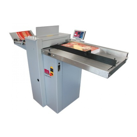
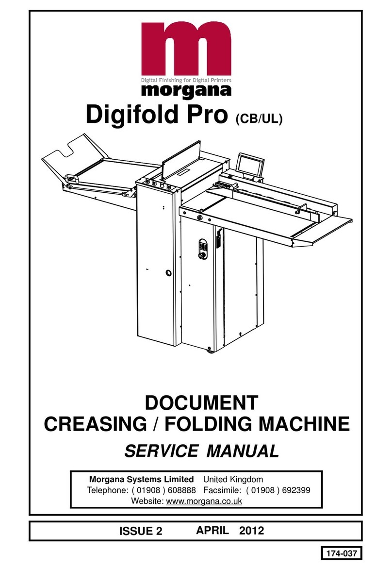
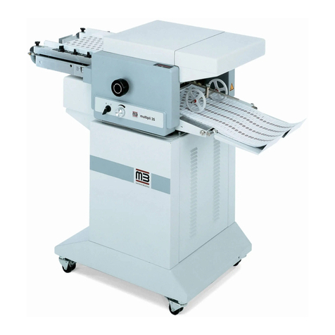
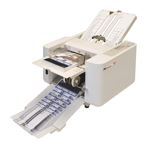
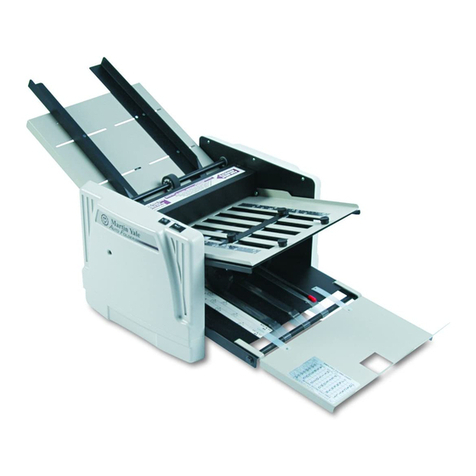
Morgana AutoFold Pro User manual

184-019 Issue 4 FEBRUARY 2013
AutoFold Pro (CB/UL)
SERVICE MANUAL
Document Folding Machine
Morgana Systems Limited United Kingdom www.morgana.co.uk Telephone: ( 01908 ) 608888 Facsimile: ( 01908 ) 692399

Page 2
INTRODUCTION
FOLDING
MORGANA Autofold Pro
i ..........Introduction
ii .........Fasteners
The purpose of this manual is to explain the procedure for dis-
mantling and re-assembly of the major assemblies on the Morgana
Autofold Pro machine.
All the engineering adjustments are shown at the end of each
relevant section.
Operator's adjustments and routine maintenance are explained in
the appropriate operators manual which should always be used in
conjunction with this manual.
It is always a good idea to have a copy of the machines illustrated
parts manual available when servicing, as its illustrations provide an
invaluable reference to the construction of the individual assemblies
used to build the machine.
All threaded fasteners are isometric & all nuts are isometric hexagon.
All screws are hardened high tensile steel.
Cap head, Button head, Socket countersunk, Shoulder bolts and
Grubscrews have internal hexagon drives which require isometric
hexagon wrenches (allen keys). Ball drivers may be used, but care
should be taken particularly when releasing screws for dismantling
to avoid breaking the driver as they cannot cope with full tightening
torques.
NOTE.........Do not substitute fasteners with low grade alternatives
which may fail or become irremovable.

Page 3
SYSTEM
Pan head and Cross-head countersunk screws all have metric Taptite threads and
Pozi-drive recesses. Use No.2 point Pozidriv or Supadriv drivers for all screws M4 &
above, and No.1 point drivers for M3 & below.
Warning
This machine is heavy care should be taken
when handling
iii ........Identification
iv ........New Machine Preparation
For general identification of areas of the machines, the following
terms are used:-
Operator side (control panel facing)
Rear of machine (opposite to control panel)
Delivery end (to the left of the operator side)
Feeder end ( on your right )
Remove all packaging materials
All metal parts, including the folding rollers have a protective coating
And any excess should be removed.
Connect the power cable to the mains supply. The machine
requires 230V 50Hz 10 Amps.
Turn the fold rollers by hand to ensure they rotate freely.
Switch on the machine and check that all functions operate.
Set up the machine to fold paper and check that the machine feeds
and folds correctly.
WARNING
WORK SHOULD BE CARRIED OUT BY A TRAINED AND COMPETENT
ENGINEER AND ALL SAFETY PROCEDURES SHOULD BE ADHERED
TO.
SWITCH OFF MAINS POWER BEFORE COMMENCING.
DO NOT USE PHILLIPS DRIVERS - THESE WILL DAMAGE THE SCREWS
& MAY SLIP, CAUSING DAMAGE OR INJURY.
Autofold Pro

Page 4
INDEX
Introduction
Section A
Section B
Section C
Section D
Section E
Section F
………………………………………………………………………..... ...PAGE
¡ Introduction ...................................................................2
¡¡ Fasteners ......................................................................2
¡¡¡ Identification ..................................................................3
iv New Machine Preparation .............................................3
…… Covers………….…. ..................................................................
Operator and Lay edge Side Doors............................... 9
Rear Cover.................................................................... 9
Operator and Lay edge Columns ................................. 10
Top Cover Assembly .................................................... 10
Delivery Conveyor Removal......................................... 11
…….Feed Bed........................................................................
Accessing the Fans and Control Board........................12
Removal of Feed Bed...................................................13
…….Infeed Roller Removal/Replacement ...............………....………....14
…….Replacing the Touchscreen Assembly ........…….…………............16
…….Electrics………..………….…………………………….......……...
Removal/Refitting Control PCB and prog board...........18
Removal/Refitting USB Flash Drive .............................19
Removal/Replacement ITX Boards .............................22
Removal/Replacement ITX PSU .................................22
Removal/Replacement Stepper Drive PCB .................22
Removal/Replacement Large PSUs’............................22
Entering Engineers tools ..............................................23
Zero Total Count...........................................................23
Setting the Measurement System ................................23
…..Optical Sensors…….………………………………………….........
..................... ...................Cleaning Sensors ..........................................................24
..... ................ ...................Changing Sensors - Leading Edge................................25
..... ................ ...................Changing Sensors - Crunch..........................................25
.... ................. ...................Changing Sensors - Folder Unit Clip 1&2.....................26
FOLDING
Page 5
SYSTEM
PAGE
…...Removing / Replacing Fold Knife Assembly……………….
…….................... ..................Upper Fold Knife.........................................................27
..................... ........................Bottom Fold Knife.......................................................27
…..Main Fold Rollers Removal…………………………................
..................... ........................Removal Third Fold Roller...........................................28
..................... ........................Removal Second/First Fold Roller...............................29
..................... ........................Main Fold Rollers - Replacement ...............................30
------------------ ----------------------
Pre-Power Setup Procedure Flow Chart .............................. 33
.................Vacuum Table Installation and Alignment............................. 34
.................Belt Tension ......................................................................... 37
................Upper Input Roller - Setting the Paralllelism & Pressure ...... 38
................Fold Rollers - Setting the Parallelism & Pressure ................. 40
................Setting The Fold Knives ........................................................ 42
................Adjusting The Top Cover Safety Switch ................................ 44
------------------ ----------------------
Powered Setup Procedure Flow Chart ................................. 45
................Control System Setup ........................................................... 46
…............Fold Roller Gap Potentiometers ...……….............................. 47
……........Sensors and Detectors .......................................................... 48
……......Delivery Assembly ................................................................. 50
--------------------------- ----------------------
Fold Setup Procedure Flow Chart ........................................ 55
.............Primary Fold Setup ............................................................... 56
Section G
Section H
Pre-Power Setup Procedure
Section 1
Section 2
Section 3
Section 4
Section 5
Section 6
Powered Setup Procedure
Section 7
Section 8
Section 9
Section 10
Fold Setup Procedure
Section 11
ENGINEERING SET-UP & CALIBRATION TECHNIQUES
Autofold Pro

Page 6
INDEX
PAGE
------------------ ----------------------
Calibration Flow Chart ................................................................. 57
.............Delivery Roller ..................................................................... 58
.............Fold Positions...................................................................... 58
.............Deflect Adjustments ............................................................ 59
............Test Run .............................................................................. 60
.............Trouble Shooting ...........................................................
.............................................Folding Unit...........................................................61
..............................................For Error Messages refer to Operator manual......63
.............Circuit Diagrams ...........................................................
.............................................. AutoFold Pro Wiring Diagram................................64
.............................................Control PCB Connection Diagram.........................65
..............................................Fuse Positions & Ratings.......................................66
Calibration
Section 12
Section 13
Section 14
Section 15
Section M
Section N
FOLDING

Page 7
SYSTEM
BLANK
PAGE
Autofold Pro

Page 8
DOCUMENT FOLDING MACHINE
Autofold Pro
Key to photograph below
1 Delivery assembly 6 Fixed Sidelay 11 Top Cover
2 Vacuum Table 7 12 Input Guide
3 Touchscreen 8 13 Fuses
4 Switch panel 9
5 Gap Sets 10
Lay Side Door
Op. Side Door
Column Lay Side
Column Op. Side
1
10
79
2
11
812
FOLDING
3
5
4
13
6

Page 9
SYSTEM
SECTION A
A.1
A.2
Covers:
The Operator Side Door.
The Lay Edge Side Door
The Operator Side Door cover which is situated adjacent to the operator, covers the Gap Set
mechanism and small stepper boards.
To remove this cover, first remove the two top fixing screws attaching the top plate, this must
be lifted upwards to clear the gap set adjuster Knobs.
Remove three screws from the right hand side and pivot the door forwards.
The Lay Side door is at the rear of the machine and is secured by three screws and a hinge,
similar to the Operator side door.
Removal of this panel allows access to the Fold Knife drive mechanism PCB and ITX Boards.
The top cover safety switch and the perforator gas strut is also inside this cover.
To remove this panel on its own remove all countersunk screws attached to the hinge and
lift away.
To replace is the reverse procedure.
Alternatively remove the front and rear covers along with the Rear Cover Panel, see below.
To open, first unscrew the three pan head screw adjacent to the touch screen and then the five
pan head screws below the feed bed which also fixes the Control Cover Door in place, hinge
backwards to open.
To remove this panel on its own, remove all countersunk screws attached to the hinge and lift
away.
To replace is the reverse procedure.
Alternatively remove the front and rear covers along with the Rear Cover Panel, see below.
The Rear Cover is situated at the output end of the machine below the delivery conveyor. This
cover is secured on each side by four posi pan head screws, fixing it to the main frame. Hinges
are attached each side of the cover to allow the side two doors to pivot from it.
To remove the rear cover including the operator side and lay edge side doors, remove the
eight posi pan head screws (4 each side) and the screws in the rear panel.
With the conveyor fully up and with one person each side, the assembly can be manouvered
out and under the rear delivery conveyor.
To replace is the reverse procedure care should be taken and two persons should carry this
out.
A.3 The Rear Cover Assembly
Autofold Pro

Page 10
SECTION A
A.4
A.5
The Operator and Lay side Columns
The Top Cover Assembly
The Operator and lay side column doors conceal the Gas struts for the Feed Bed.
To remove the doors open them up using the handles provided and remove the six screws
securing the hinge to the main frame.
To replace is the reverse procedure.
The Top Cover Assembly is hinged on top of the Machine and covers the Mechanism, this
hinges upwards to allow access to the Main Rollers, the Input Rollers and the Top Sensors.
This cover can be removed from the machine as follows.-
1. Open the Lay Side Door as previously described.
2. Open upwards.
3. Peel back the sound adsorbent foam to allow access to the two posi pan head fixing
screws which can be unscrewed from the pivot shaft.
4. From the rear of the machine slide the guard pivot shaft out taking care not to damage
the microswitch. the cover can now be removed. Take care not lose/drop the nylon washers at
each end of the pivot shaft.
To replace is the reverse procedure, ensure the micro switch is correctly set after this
procedure.
FOLDING

SYSTEM Page 11
A.6 Delivery Conveyor
To Remove the Delivery Conveyor the rear cover should be removed for access.
Pivot the delivery down at 45 degrees using the handle on the end and turn the ‘delivery
locking screw’ anti-clockwise to lock the delivery strut into this position. Shown in photo
below.
Using the body of the gas strut unscrew from its clevis until released.
Unscrew the support blocks each side using a 5mm A/F allen key at the top fixing and
loosen the bottom screw.
Pivot both blocks forward (note the operator side will have a resistance from the perf gas
strut)
The assembly can now be lifted clear.
SECTION A
Delivery Locking Screw
Autofold Pro

Page 12
SECTION B
Feed Bed
Accessing the Fans and control board
1. Remove the two Pan Heads securing the input guide to the end of the bed. (be carefull
not to lose the spacer they secure).
2. With the Guard removed Unscrew the Countersunk Screws in the Feed bed.
3. Lift off the bed. This provided access to the fans and board.
4. To remove the fans, Unscrew the four Cap head screws securing the fans to the
center support.
FOLDING

Page 13
SYSTEM
SECTION B
Removal of Feed Bed unit
1. Remove the top panel of the Feed Bed as previously explained.
2.
3.
4. Open the Lay side column and remover the set screw from the top of the gas strut eye
5. Open the Operator column and loosen the support knob.
6.
With access to the fan control board remove the connections to the rest of the
machine.
Now remove the Latches on either side of the bed near the operator and lay doors.
This requires unscrewing the two pan head screws diagonally opposite each other as
shown below.
Support the feed bed from underneath and remove the support shaft that holds the
gas struts in place. (CAUTION, removal of shaft will cause Feed Bed to pivot. Ensure
Bed is supported before removal of shaft).
7. With the Shaft removed you can now slide the bed out of the location plates and lift
the bed free from the machine
To replace is the reverse procedure. Use the support knob to tighten and fix the
gas struts into place. (To align the Bed correctly see page 35).
Autofold Pro
Latch
Unscrew
Pan Heads

Page 14
SECTION C
REMOVAL/REPLACEMENT OF INPUT ROLLERS
All side covers and the top cover should be removed to ease access to the infeed rollers.
1. Remove the lead edge sensor housing by unscrewing the two fixing screws from the
rear of the machine and leave loose in situ.
2. Unscrew and remove the input roller gap locking screw from the slot in the frame.
3. From the lay side of the machine remove the circlip from the shaft housing.
4. The roller can now be removed through the hole in the operator sideplate.
6. Remove the circlip from the shaft on the operator side.
7. Remove the pulley from the opposite end and then loosen the layside hub securing set
screw located in the aluminium side plate edge. Withdraw the roller assembly through
the
8. Replace the roller in the reverse manner.
TOP INPUT ROLLER
BOTTOM INPUT ROLLER
hole in the layside side plate.
FOLDING

Page 15
SYSTEM
Layedge Side
Operator Side
Autofold Pro

Page 16
SECTION D
Replacing the Touch Screen Assembly
Ensure the mains power is turned off but with the plug in the socket, this maintains an
earth to reduce static damage.
1. Open the hinged Lay Side Cover to expose the ITX board.
2. Unplug the USB connector and nine way “d” type plug from the ITX board, then
carefully remove the white power connector (this is tight and the wires can
easily be pulled from the plug)
3. Through the rear of the metal support loosen the two socket head screws using
a 4mm A/F Allen key. see below.
4. Carefully lift the unit up and through the top cover aperture.
Replacement is the opposite procedure.
Calibration of the Touch Screen.
1. Switch on the power and wait for the main screen to appear before commencing
to check the horizontal and vertical position of the display.
The position of the display within the surround is achieved by operating the
centre button at the rear of the housing, press this a number of times to obtain
the correct orientation required, move to the next button to move the position to
centralize horizontal.
2. Select the tools menu tab, and then select the Touch Screen calibration icon.
Using a plastic pointer, soft leaded pencil, biro cap etc. and with gentle pressure.
Touch the centre of the cross in each corner of the Touch Screen, as prompted, by
the hand graphics. This procedure will calibrate the Touch Screen.
Brightness
Contrast
Horizontal
Vertical
Brightness
Contrast
Horizontal
Vertical
UP
(Increase value)
UP
(Increase value)
DOWN
(Decrease value)
DOWN
(Decrease value)
Display
ON/OFF)
Display
ON/OFF)
AV / Display
Channel
AV / Display
Channel
FOLDING

Page 17
SYSTEM
Brightness
Contrast
Horizontal
Vertical
UP
(Increase value)
DOWN
(Decrease value)
Display
ON/OFF)
AV / Display
Channel
Autofold Pro
SECTION E
ELECTRICS: The PRO Control System.
The Morgana PRO control system is essentially a computer system just like the PC you
use at home. Unlike your Microsoft Windows PC, the PRO system uses a LINUX operating
system and runs only one program, which is the machine control program for the particular
machine that it is installed on.
Block Diagram of the PRO Control System
ITX
Motherboard
Controller
PCB
ATX PSU
E-Stop
240V AC
5V DC / 12V DC / 0V
RED/ YELLOW / BLACK
<- Comms ->
GUI
USB Stick / Flash
Drive
(Hard Drive)
Touch Panel
VGA
Digital<>Analogue
Interface PCB
Machine Control
Processor PCB
Touchscreen
Display
115V AC
Transformer
Assembly
110V AC /

Page 18 FOLDING
SECTION E
ELECTRICS: REMOVAL/REFITTING PCB’s
REPLACEMENT OF MAIN CONTROL P.C.B.
This PCB controls all functions of the machine and houses the Main Program PCB.
The use of an antistatic wrist band should be used during work on the main control PCB.
Unplug all the green plugs from the PCB.
Using a posi-drive screw driver, unscrew the five fixing screws and carefully remove the PCB.
Switch the mains power off and disconnect from the mains supply.
Access is from the Lay Side Door. (see section on covers for removal).
When fitting a new board it is important that the switch, , must be set in the correct
position. For machines with Serial No. 180209 or higher the switch must be set over to the left
in the position; these machines were fitted with as
standard. For machines with Serial numbers earlier than 180209 the switch must generally be
set over to the right in the position, unless the machine has been upgraded to
include Earlier Machines that have been upgraded with
will have a main processor revision of F1.2x2 or higher and a
touchscreen software revision of AF1.0x1 or higher; for these machines the switch must be set
over to the left in the position. See technical bulletin TB2744 Iss.B. for further
information.
SWITCH (SW1)
NOTE.
SW1
AUTO EDGE Lead Edge Auto Sensing
POT EDGE
Lead Edge Auto Sensing. Lead
Edge Auto Sensing
AUTO EDGE

Page 19
SYSTEM
Autofold Pro
SECTION E
REPLACEMENT OF PROCESSOR BOARD.
REPLACEMENT OF USB FLASH DRIVE.
This Small PCB is plugged onto the face of the Main Control PCB and houses the Program
Chip.
The use of an antistatic wrist band should be used during work on this Processor PCB.
Switch the mains power off and disconnect from the mains supply.
Access is from the hinged Control Cover located beneath the feed bed. (see section on covers
for removal).
The USB Flash Drive controls all functions of the graphics and touch screen operation.
The External USB Flash Drive and the Internal USB Flash Drive devices (shown in FIG.2
below) have the same functionality. Either one of these devices could be supplied as a
replacement.
When fitting an Internal USB Flash Drive its orientation is important. Note the position of
the Lock Recess shown in FIG.2 below. The lock must also be in the unlocked position.
Ensure that the device fits securely and is fully inserted.
If the Internal Flash Drive is fitted the wrong way round it will not be damaged, it just won’t
work. Power down the machine and turn it round.
To remove care should be used, lifting from the bottom and gently rocking from side to side
seems to work the best.
Replacement is the reverse procedure, care should be taken that the correct orientation is
observed. (oscillator uppermost)
When changing the above board it may be necessary to recalibrate the machine.
Take note of any calibration settings prior to zeroing the count.
Note.
IMPORTANT!
Processor Board

Page 20 FOLDING
External USB Sockets
Internal USB Headers
Installation Procedure.
1. Note the current machine calibration settings.
2. Power down the machine and remove the power cord.
3. Change the USB Flash Drive (Red or Green depending on what is currently fitted).
It is important to choose the right colour in accordance with the machine you are
upgrading. See TB2705 for further information on when to use Red or Green USB Flash
Drives. As a general rule replace like for like (i.e. Green for Green and Red for Red).
4. Power the machine up.
5. To access the machine menu, open the calculator and type 608888; then press X to exit
the calculator screen.
6. Choose the machine type from the list and perform a power cycle when prompted.
7. Re-enter the calibration settings.
NOTE.
FIG.1 and FIG.2 above show the Internal USB Flash Drive position for the current
Gigabyte ATX mother board. FIG.3 and FIG. 4 below show the Internal USB Flash Drive
positions for the previously used Jetway and Asrock ATX mother boards.
FIG.1 FIG.2
FIG.3 FIG.4
Asrock ATX Mother Board
Jetway ATX Mother Board
External USB Flash Drive
Internal USB Flash Drive
Lock
Recess
Other manuals for AutoFold Pro
1
Table of contents
Other Morgana Folding Machine manuals

Morgana
Morgana Digifold 5000P User manual

Morgana
Morgana MB300 XL Pro User manual

Morgana
Morgana AutoFold Pro User manual

Morgana
Morgana TF MEGA-S User manual

Morgana
Morgana Square fold 104 User manual

Morgana
Morgana UFO Manual

Morgana
Morgana DIGIFOLD User manual

Morgana
Morgana Digifold Pro CB User manual

Morgana
Morgana DigiFold Pro User manual

Morgana
Morgana DocuFold Pro User manual