MORIA EVOLUTION 3E User manual

Ref.: 65060/INTL
MORIA S.A. – 15, rue Georges Besse - 92160 ANTONY – France
#65060/INTL-K-10-2020
0459
Année de première mise sur le marché : 2005

EN - EVOLUTION 3E
INSTRUCTION MANUAL For Serial Numbers 5000 and Above........................................................................................1-11
FR - EVOLUTION 3E
MANUEL UTILISATEUR Numéros de série 5000 et plus................................................................................................ 12-22
ES - EVOLUTION 3E
MANUAL DE INSTRUCCIONES Para números de serie 5000 y superiores ................................................................ 23-33
IT - EVOLUTION 3E
MANUALE DELL’UTENTE Per i numeri di serie 5000 o superiori .................................................................................. 34-44
DE - EVOLUTION 3E
BENUTZERHANDBUCH für die Seriennummern ab 5000 ............................................................................................. 45-55
NL - EVOLUTION 3E
INSTRUCTIEHANDLEIDING Voor serienummers 5000 en hoger.................................................................................. 56-66
PT - EVOLUTION 3E
MANUAL DE INSTRUÇÕES Para Números de Série 5000 e Superiores ...................................................................... 67-77
SV - EVOLUTION 3E
INSTRUKTIONSMANUAL För Löpnummer 5000 och Över............................................................................................ 78-88
TR - EVOLUTION 3E
KULLANIM TALİMATLARI EL KİTABI 5000 ve Üzeri Seri Numaraları İçinr .................................................................... 89-99

1
4
2
3
A
B
E1
D1
E2
D2
E3
D3
3a 3b
C
19361
19381
19381J19381C

F2
F3F4
F5F6F7
F8
G1G2
G3G4G5
H
E4E5F1

#65060/INTL-K-10.2020 MORIA 1
CONTENTS
I. DISCLAIMER..................................................................................................................................... 2
A. MAINTENANCE AND WARRANTY ................................................................................................... 2
B. USE OF GENERIC PRODUCTS AND REUSE OF SINGLE-USE CONSUMABLES ........................ 2
II. GUIDANCE AND MANUFACTURER’S DECLARATION: ELECTROMAGNETIC EMISSIONS AND
IMMUNITY.......................................................................................................................................... 2
III. EQUIPMENT AND ACCESSORIES LIST ......................................................................................... 2
A. EQUIPMENT LIST.............................................................................................................................. 2
B. ACCESSORIES LIST ......................................................................................................................... 3
IV. TECHNICAL SPECIFICATIONS ........................................................................................................ 6
V. REGULATORY INFORMATION ......................................................................................................... 6
VI. INTENDED USE................................................................................................................................. 6
VII. LABELING INFORMATION ............................................................................................................... 7
VIII.INSTALLATION AND CONNECTION ................................................................................................ 7
A. INSTALLATION RECOMMENDATIONS............................................................................................. 7
B. ELECTRICAL SETTING ..................................................................................................................... 7
C. BATTERY TEST.................................................................................................................................. 8
D. CONNECTING THE ASPIRATION TUBING....................................................................................... 8
E. VACUUM TEST .................................................................................................................................. 8
F. LOW VACUUM FUNCTION................................................................................................................ 9
G. MANUAL MODE (CB, CBm, CBSU, ONE, ONE USE) ...................................................................... 9
1. PNEUMATIC TURBINE CONNECTIONS .......................................................................................... 9
2. DISASSEMBLY OF THE NITROGEN/AIR SUPPLY ........................................................................ 10
H. AUTOMATED MODE (M2, M2SU, ONE USE-PLUS, EPI-K™)........................................................ 10
IX. USE OF FOOTPEDAL ......................................................................................................................11
A. COMPATIBILITY FOOTPEDAL-CONSOLE ......................................................................................11
B. COMPATIBILITY FOOTPEDAL-HANDPIECE...................................................................................11
C. MANUAL MODE ................................................................................................................................11
D. AUTOMATED MODE.........................................................................................................................11
X. TROUBLE SHOOTING .....................................................................................................................11
A. POWER SUPPLY ..............................................................................................................................11
B. VACUUM LOSS................................................................................................................................ 12
C. RESIDUAL VACUUM........................................................................................................................ 12
D. TURBINE PRESSURE (MANUAL MODE) ....................................................................................... 12
XI. CARE & MAINTENANCE ................................................................................................................ 12
A. HOW TO SELECT THE OPERATING VOLTAGE (115V OR 230V POSITION) ............................... 12
B. INSTALLING A NEW BATTERY ....................................................................................................... 12
C. REPLACING FUSES........................................................................................................................ 13
XII. WARRANTY..................................................................................................................................... 13
A. SCOPE OF WARRANTY.................................................................................................................. 13
B. NON-APPLICATION OF WARRANTY.............................................................................................. 13
C. WARRANTY PERIOD....................................................................................................................... 13
D. LIABILITY ......................................................................................................................................... 13
XIII.DRAWINGS ...................................................................................................................................... 13
A. CONTROL UNIT (FRONT) ............................................................................................................... 13
B. CONTROL UNIT (BACK).................................................................................................................. 13
C. FOOTPEDAL.................................................................................................................................... 13
D. CONNECTING AND DISCONNECTING NITROGEN/AIR HOSE (#19120) .................................... 13
E. HOW TO SELECT THE OPERATING VOLTAGE (115V OR 230V POSITION) ............................... 13
F. CHANGING THE BATTERY............................................................................................................. 13
G. CHANGING FUSES ......................................................................................................................... 13
H. INSTALLING TUBING....................................................................................................................... 13

#65060/INTL-K-10.2020 MORIA 2
This instruction manual is for EVOLUTION 3E with serial numbers 5000 and above.
For the EVOLUTION 3E with serial numbers below this number, please refer to user manual (#65051).
The most recent version of this user guide and additional information on your keratome are available on
MORIA website: http://www.moria-surgical.com.
I. DISCLAIMER
A. MAINTENANCE AND WARRANTY
The EVOLUTION 3E system has been designed for optimal operation, provided that the recommendations
listed in this user manual are followed carefully.
The lifetime of the Evolution 3E system is 5 years. This lifetime can be extended to 15 years if the maintenance
plan described above is strictly followed. The maintenance operations in the fth and tenth years (M5 and
M10) must be carried out by Moria. They guarantee the electrical safety and operating performance of the
Evolution 3E Console and thus the user’s and the patient’s safety.
The other annual, intermediate maintenance operations will be carried out by Moria or by its representative
who will have been previously trained and authorized by Moria. This representative must have a valid training
certicate and must use only spare parts supplied by Moria.
MORIA shall not guarantee the performance of the Evolution 3e system and patient and user safety if the
maintenance plan is not followed.
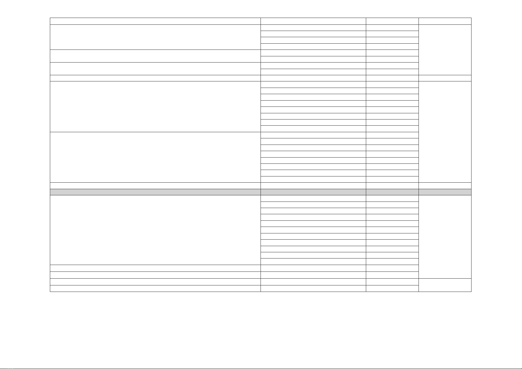
Years Ref. Check Electrical
safety
Remplacement
of the primary
circuit
Battery
change
Turbine
gasket
change
Pump
change
Tubing
change
Engine board
change
Vacuum
solenoid
valve change
1M1 yes no no no yes no yes no no
2M2 yes no no no yes no no no no
3M3 yes no no no yes no yes no no
4M4 yes no no no yes no no no no
5 M5 yes yes no yes yes yes yes no no
6M6 yes no no no yes no no no no
7M7 yes no no no yes no yes no no
8M8 yes no no no yes no no no no
9M9 yes no no no yes no yes no no
10 M10 yes yes yes yes yes yes yes yes yes
11 M11 yes no no no yes no no no no
12 M12 yes no no no yes no yes no no
13 M13 yes no no no yes no no no no
14 M14 yes no no no yes no yes no no
15 No maintenance
If, for any reasons, the system does not perform properly, have it checked immediately by MORIA. MORIA
strongly recommends having the system thoroughly inspected by MORIA on a routine basis every year.
The use of materials and/or components of a brand other than MORIA with the EVOLUTION 3E system will
immediately nullify the MORIA warranty. MORIA may not be held responsible for any damage resulting from
the use of materials and/or components of a brand other than MORIA.
As only MORIA and its agents are fully expert in MORIA products, servicing and maintenance must be carried
out by MORIA or its approved agents.
MORIA shall not be held liable for any malfunction or damage to the apparatus, poor results, or surgical
complications due to maintenance being having been carried out by an unqualied operator or third party.
Any such unauthorised intervention shall render the guarantee and any maintenance contract null and void.
B. USE OF GENERIC PRODUCTS AND REUSE OF SINGLE-USE CONSUMABLES
Single-use devices should not be re-used. Doing so will negatively affect their clinical performance and
increase the potential for adverse events.
The reuse of single-use products, or the use of consumables other than those supplied by MORIA, may entail
serious surgical consequences for the patient and dama ge the microkeratome.
MORIA shall not be held liable in the event of a malfunction or damage to the microkeratome, poor results or
surgical complications due to the reuse of a single-use product, or the use of consumables other than those
supplied by MORIA.
MORIA handpieces must only be connected to MORIA devices (console unit, heads, suction rings, etc.).
All warranties become null and void if the microkeratome degrades or malfunctions due to such practices.
The most recent version of this user guide and additional information on your keratome are available on
MORIA website: http://www.moria-surgical.com.
II. GUIDANCE AND MANUFACTURER’S DECLARATION: ELECTROMAGNETIC
EMISSIONS AND IMMUNITY
Refer to annexe document (#65073).
III. EQUIPMENT AND ACCESSORIES LIST
A. EQUIPMENT LIST
Designation Regulatory
designation
MORIA
reference
EVOLUTION 3E Console (S/N above 5000) EVOLUTION 3e CONTROL
UNIT
19380
EVOLUTION 3-3E Control Footpedal FOOT PEDAL FOR
EVOLUTION
19361
EVOLUTION 3E Control Footpedal Epi-K™ EVOLUTION 3e
FOOTSWITCH
19381
Evolution 3E Footswitch - China EVOLUTION 3e
FOOTSWITCH
19381C
Evolution 3E footswith - Japan EVOLUTION 3e
FOOTSWITCH
19381J
EVOLUTION 3 Supply Cords (CEE) (2.50m) / Cable (CEE) EVOLUTION 3 SUPPLY
CORD (EEC)
19362
EVOLUTION 3 Supply Cords (USA) (2.50m) / Cable (USA) EVOLUTION SUPPLY
CORD (USA)
19363
EVOLUTION 3 Supply Cords (UK) (2.50m) / Cable (UK) EVOLUTION 3 SUPPLY
CORD (UK)
19364
EVOLUTION 3 Supply Cords (China) (2.50m) / Cable (China) EVOLUTION 3 SUPPLY
CORD CHINA
19516
EVOLUTION 3 Supply Cords (Brazil) (2.50m) / Cable (Brazil) EVOLUTION 3 SUPPLY
CORD BRAZIL
19521
Supply cord USA SUPPLY CORD (USA) 19451
Carrying Case N/A 19511
User manual N/A 65060/INTL
User manual - China N/A 65060/ZH
User manual- Brazil N/A 65060/BR
Annexe “Guidance and manufacturer’s declaration: electromagnetic emissions and
immunity”
N/A 65073

#65060/INTL-K-10.2020 MORIA 3
Designation Regulatory designation MORIA reference User manual
Dry medical grade nitrogen gaz / Dry and ltered medical grade air Gas Supply Hose*
*This hose is supplied when the EVOLUTION 3E unit is ordered together with MORIA manual microkeratomes" GAS SUPPLY TUBING 19120
Tonometer BARRAQUER autoclavable tonometer 19042
Aspiration tubing Evolution 2-3-3E tubing x10 19138
Turbine hose (for ONE or CBm-ALTK turbine) SHORT CONNECTOR TURB FLEX HOSE 19353
Turbine handpiece for ONE microkeratome GAS TURBINE FOR LSK ONE 19155
Turbine handpiece for CB microkeratome LSK C & B TURBINE MOTOR 19303
M2 handpiece M2 ELECTRIC MOTOR 19326
Epi-K™ handpiece (green color) EPI-K HANDPIECE 19342
One Use-Plus handpiece (blue color) ONE USE PLUS MOTOR 19345
One Use-Plus One-Handed handpiece (blue color) ONE HAND ONE USE PLUS HANDPIECE 19345OH
One Use-Plus hanpiece for articial chamber (black color) OUP HANDPIECE F/ ARTIFCIAL CHAMBER 19175
Reusable Epi-K™ metal ring size -1, 0, +1 with stops at 7.5 - 8.0 - 8.5 - 9.0 (green color)
EPI-K REUSABLE SUCTION RING -1 19389/-1
65043
EPI-K REUSABLE SUCTION RING 0 19389/0
EPI-K REUSABLE SUCTION RING +1 19389/1
Reusable Epi-K™ metal ring size Large Diameter (LD) -1 with stops at 8.0 - 8.5 - 9.0 - 9.5 (green color) EPI-K LD REUSABLE SUCTION RING -1 19399/-1
Box of 10 sterile Epi-K™ heads EPI-K HEAD 19390
Box of 10 Epi-K™ ring -1 and 10 Epi-K™ heads EPI-K SET (-1 RING) 19384 65044
One Use-Plus: ring –1 and Head SBK (90) or 130 ONE USE PLUS SBK SET (90/-1) 19336/90
65039
ONE USE PLUS SET (130/-1) 19336/130
One Use-Plus: ring 0 and Head SBK (90) or 130 ONE USE PLUS SBK SET (90/0) 19337/90
ONE USE PLUS SET (130/0) 19337/130
One Use-Plus: ring –1 Large Cut and Head Large Cut 110L and 130L ONE USE PLUS 110 LARGE CUT SET 19354/110
ONE USE PLUS 130 LARGE CUT SET 19354/130
One Use-Plus Large cut reusable metal ring size -1, 0 with stops at 7.5 - 8.0 - 8.5 - 9.0 (mauve color) OUP LC -1 REUSABLE SUCTION RING 19519/-1
65040
One Use-Plus reusable metal ring size -1, 0 with stops at 7.5 - 8.0 - 8.5 - 9.0 (blue color) OUP REUSABLE SUCTION RING -1 19391/-1
OUP REUSABLE SUCTION RING 0 19391/0
One Use-Plus reusable metal ring size +1, +2, +3 with stops at 7.0 - 7.5 - 8.0 - 8.5 (yellow color)
OUP REUSABLE SUCTION RING 1 19391/1
OUP REUSABLE SUCTION RING 2 19391/2
OUP REUSABLE SUCTION RING 3 19391/3
One Use-Plus reusable metal oval rings size +1, +2, +3, with stops at 7.0 - 7.5 – 8.0 - 8.5 (grey color)
OVAL FLAP OUP METAL SUCTION RING +1 19391/1/OV
OVAL FLAP OUP METAL SUCTION RING +2 19391/2/OV
OVAL FLAP OUP METAL SUCTION RING +3 19391/3/OV
Box of 10 sterile heads One Use-Plus SBK (90) or 130 ONE USE PLUS SBK HEAD 19393/90
ONE USE PLUS 130 HEAD 19393/130
M2-M2SU suction ring (size -1, 0, +1, +2, +3)
M2 SUCTION RING -1 19325/-1
65013
M2 SUCTION RING 0 19325/0
M2 SUCTION RING +1 19325/1
M2 SUCTION RING +2 19325/2
M2 SUCTION RING +3 19325/3
M2-M2SU suction ring size -1 Large-Cut M2 SUCTION LARGE CUT RING -1 19379/-1
M2 metallic head M2 HEAD 110 19327/110
M2 HEAD 130 19327/130
Box of 10 sterile disposable M2 blades
M2 BLADE 19329
M2 BLADE X100 (CHINA) 19329C4
M2 BLADE X50 19329L3
Box of 10 sterile disposable M2SU heads
M2SU 90 HEAD 19334/90
19334/130
M2SU 90 HEAD X80 (CHINA) 19334/90C5
B. ACCESSORIES LIST

#65060/INTL-K-10.2020 MORIA 4
Designation Regulatory designation MORIA reference User manual
Microkeratome CB manual suction rings (size -1, 0, +1, +2)
LSK C & B MANUAL FIXATION RING -1 19309/-1
65005
LSK C & B MANUAL FIXATION RING 0 19309/0
LSK C & B MANUAL FIXATION RING 1 19309/1
LSK C & B MANUAL FIXATION RING 2 19309/2
Box of 10 sterile CBm blades CBM BLADE 19333
CBM BLADE X50 19333L3
Box of 10 sterile CBSU heads CBSU 110 HEAD 19312/110
CBSU 130 HEAD 19312/130
Box of 10 ONE Microkeratome blades ONE MICROKERATOME BLADE 19137 65006 - 65007
CBm-ALTK Head
CBM / ALTK HEAD 110 19170/110
65078
CBM / ALTK HEAD 130 19170/130
CBM / ALTK HEAD 150 19170/150
CBM / ALTK HEAD 200 19170/200
CBM / ALTK HEAD 250 19170/250
CBM / ALTK HEAD 300 19170/300
CBM / ALTK HEAD 350 19170/350
CBM / ALTK HEAD 400 19170/400
Box of 5 sterile CBSU heads for articial chamber
CBSU 50 HEAD - ART. CHAMBER 19178/50
CBSU 90 HEAD - ART. CHAMBER 19178/90
CBSU 110 HEAD - ART. CHAMBER 19178/110
CBSU 130 HEAD - ART. CHAMBER 19178/130
CBSU 200 HEAD - ART. CHAMBER 19178/200
CBSU 250 HEAD - ART. CHAMBER 19178/250
CBSU 300 HEAD - ART. CHAMBER 19178/300
CBSU 350 HEAD - ART. CHAMBER 19178/350
Disposable CBSU guide ring for disposable articial chamber (19182) CBSU GUIDE RING FOR ARTIFICIAL CHAMBER 19180 N/A
Box of 5 sterile One Use Large-Cut heads for articial chamber
OU LC 110 HEAD ARTIFICIAL CHAMBER 19184/110
65009
OU LC 130 HEAD ARTIFICIAL CHAMBER 19184/130
OU LC 150 HEAD ARTIFICIAL CHAMBER 19184/150
OU LC 200 HEAD ARTIFICIAL CHAMBER 19184/200
OU LC 250 HEAD ARTIFICIAL CHAMBER 19184/250
OU LC 300 HEAD ARTIFICIAL CHAMBER 19184/300
OU LC 350 HEAD ARTIFICIAL CHAMBER 19184/350
OU LC 400 HEAD ARTIFICIAL CHAMBER 19184/400
OU LC 450 HEAD ARTIFICIAL CHAMBER 19184/450
OU LC 500 HEAD ARTIFICIAL CHAMBER 19184/500
OU LC 550 HEAD ARTIFICIAL CHAMBER 19184/550
One Use Large-Cut guide ring for ALTK articial chamber (19161-19162) OU LC RING FOR ALTK ARTIFICIAL CHAMBER 19168
One Use-Plus Large-Cut guide ring for ALTK articial chamber (19161-19162) OUP LC RING F/ ALTK ARTIFICIAL CHAMBER 19173
Disposable One Use Large-Cut guide ring for disposable articial chamber (19182) OU LC GUIDE RING FOR ARTIFICIAL CHAMBER 19186 N/A
Disposable One Use-Plus Large-Cut guide ring for disposable articial chamber (19182) OUP LC GUIDE RING F/ ART. CHAMBER X5 19187

#65060/INTL-K-10.2020 MORIA 5
Designation Regulatory designation MORIA reference User manual
Base of the ALTK articial chamber Donor articial chamber base 19161
65009
ALTK/CBm cover with guide ring ALTK/CBm cover with guide ring 19172
Universal chamber cover for ALTK articial chamber Articial chamber cover for ALTK 19162
Infusion tubing set for articial chamber INFUSION TUBING SET FOR ARTIFICIAL CHAMBER 19181 N/A
Disposable articial chamber ONE - SU ART. CHAMBER x1 19182
OUP Ring sterilization box OUP ring sterilization box 22519513 65040
Polymer box for OUP handpiece Polymere box for OUP handpiece 22519514 65039-65040
Sterilization box for M2 Sterilization box for M2 22519330 65013-65062
ALTK sterilization box ALTK sterilization box 22519167
N/A
ALTK lenses storage box ALTK lenses storage box 22519169
Storage box for M2 Storage box for M2 22519331
Storage box F/art. Chamber OUP handpiece STORAGE BOX F/ART. CHAMBER OUP HANDPIECE 22519174
Sterilization box for LSK Sterilization box for LSK 22519139
LSK CB sterilization tray LSK CB sterilization tray 22519343
OUP motor loosening key OUP MOTOR LOOSENING KEY 19345C
Applanator lense 8-10 F/LSK C&B Applanator lense 8-10 F/LSK C&B 19311 65005-65078
ALTK applanator lense 6-8-10 ALTK applanator lense 6-8-10 19166
65009-65078ALTK applanator lense 7-9-11 ALTK applanator lense 7-9-11 19165
Articial Chamber cover for ALTK/CBm Articial Chamber cover for ALTK/CBm 19171
Articial chamber guide ring for ALTK Articial chamber guide ring for ALTK 19164 65009
ONE head blade push ONE head blade push 19135 N/A

#65060/INTL-K-10.2020 MORIA 6
IV TECHNICAL SPECIFICATIONS
The control unit is mainly composed of the following elements:
• 1 x 12V-7Ah battery (back-up)
• 1 x transformer
• 2 x vacuum pumps: vacuum circuit (main pump + « back-up » pump)
• valves for the vacuum & gas circuit
• 1 x gas regulator used for the set up of the nitrogen pressure going to the turbine (manual
microkeratomes)
• Electronic boards.
Reference mm kg Pressure Elect. Supply
19380 430 x 240 x 190 13.6 IN : 4-6 bars / 58-87 psi
OUT : 2.5-3.5 bars / 36-50 psi
Precision of displayed values:
+/-0,2bar = 2,9 psi.
Vacuum display: +/- 30 mmHg
100-120V / 220-240V
50/60Hz
Fuse : 500 mA high switching power
Battery :12 V - 7 Ah (Pb)1
Power input: 50 VA
19381 Double footswitches:
220 x 200 x 60
Single footswitch :
100 x 70 x 30
2.55
19361 Double footswitches:
160 x 130 x 70
Single footswitch :
100 x 70 x 30
1.05
19381C Double footswitches:
160X130X70
Simple pédale:
100X70X30
1.05
19381J Double pédale:
220X200X30
Single footswitch:
100X70X30
2.55
1 If a battery change is necessary, the used battery is classied as waste, which must be dealt with according to the specic regulations for
collection, treatment, recycling and disposal set out in directive 2006/66/EC of 9 September 2006 relating to batteries and accumulators and
waste batteries and accumulators. As such the battery must be disposed of at an appropriate collection point.
The Evolution 3E control unit and the electrical motors / turbines must follow the following conditions:
Temperature Humidity rate
(without condensation)
Atmospheric
pressure
Transportation 5 - 45°C / 41°F – 113°F 30 - 90%
Storage 10 - 40°C / 50°F – 104°F 30 - 75%
Normal conditions of use 10 - 40°C / 50°F – 104°F 30 - 75% 70 - 106 kPa
V. REGULATORY INFORMATION
MORIA S.A.
15, rue Georges Besse - 92160 Antony - France
Phone +33 (0) 146 744 674
Fax +33 (0) 146 744 670
http://www.moria-surgical.com
Electrical Safety Standard, electromagnetic
compatibility IEC 60601-1 Classe I type BF
Annexe “Guidance and manufacturer’s
declaration: electromagnetic emissions and
immunity” Refer to annexe document (#65073).
Customer Service Information Contact your local dealer or MORIA.
EUROPE 0459 according to MDD 93/42/CEE
USA
Product registered at the Food and Drug Administration (FDA).
Caution USA only: Federal law restricts the use of this device to
physicians or licensed practitioners.
For EU customers only: this symbol indicates that within the
European Union, the product must be discarded in a separate
collection bin at the end of its useful life. This applies not only to
this device, but also all accessories, including the footpedal and
electrical motors, regardless of whether those accessories are
marked with the symbol. Do not dispose as unsorted municipal
waste.
For users out of EU: please refer to local environmental regulatory
regarding waste of electrical and electronic equipment.
VI. INTENDED USE
The power unit has been designed to operate Moria keratomes by means of electric motor or turbine.
Evolution 3E console must be used only by experienced ophthalmic surgeons with specic knowledge and
training in corneal surgery.

#65060/INTL-K-10.2020 MORIA 7
VII. LABELING INFORMATION
XXXXXX CATALOGUE NUMBER OR SKU
XXXXXXXX SERIAL NUMBER
YYYY/MM/DD DATE OF MANUFACTURE
XXXXXXX MANUFACTURER
XXXXXX
CAUTION : CONSULT INSTRUCTIONS FOR USE FOR ANY IMPORTANT INFORMATION
ABOUT THE SECURITY
XXXXXX CONSULT OPERATING INSTRUCTIONS
DISCARD IN A SEPARATE COLLECTION BIN
WARNING AGAINST ELECTROSTATIC DISCHARGES
WARNING AGAINST INTERFERENCE RISK
REFER TO USER MANUAL
SIGN OF GENERAL SAFETY
ALTERNATIVE CURRENT
TYPE « BF » APPLIED PARTS: PROTECTION AGAINST ELECTRIC SHOCK :
• LEAKAGE CURRENT
• GROUNDED POWER SYSTEM
40°C
10°C
75%
30%
NORMAL CONDITIONS OF USE
EVO3E CONTROL UNIT AND MOTORS/TURBINES:
TEMPERATURE: 10°C – 40°C / 50°F – 104°F, HUMIDITY RATE: 30 - 75%
35°C
15°C
70%
30%
NORMAL CONDITIONS OF USE
SINGLE USE ITEM :
TEMPERATURE: 15°C – 35°C / 59°F – 95°F, HUMIDITY RATE: 30 - 70%
IP X6 FOOTSWITCH PROTECTED AGAINST POWERFUL WATER JETS
IP X8 FOOTSWITCH PROTECTED AGAINST WATER SUBMERSION BEYOND 1 METER (3,3 FEET)
THIS SIDE UP
FRAGILE
KEEP DRY
CAUTION FOR USA ONLY: US FEDERAL LAWS RESTRICT THIS DEVICE TO SALE BY, OR ON
THE ORDER OF, A PHYSICIAN.
VIII. INSTALLATION AND CONNECTION
A. INSTALLATION RECOMMENDATIONS
Following is a list of general recommendations when installing the EVOLUTION 3E console:
• Make sure the console is installed no more than 2 meters away from user
• The console must remain in front of user during operation to visualize every indication (value,
warning)
• User must be able to hear signals from EVOLUTION 3E console properly
• User must be able to disconnect suction from aspiration tubing connector
• User must be cautious about EVOLUTION 3E console displacement due to its height, dimensions
and connections
• The EVOLUTION 3E console must not be installed above or close to a radiating device.
• All applied parts must be used in normal condition of use, and on a routine surgical basis with
respect to their intended use according to the instructions for use.
WARNING : The microkeratomes electric motors and turbine can reach a temperature over 41°C.
Moria recommends to use the motors and rings not longer than 1 min and to prevent any contact of
motors with patient tissues.
B. ELECTRICAL SETTING
Steps What to do IMPORTANT WARNINGS Related
picture
1 Using the screw
connector, plug in the
footpedal connector
(#19361, 19381,
19381C, 19281J) to the
rear panel of the console
Finger tight only B8
C
2 Connect the power
supply cord to the main
power supply
NEVER OPERATE WITHOUT MAIN POWER SUPPLY.
Before using the EVOLUTION 3E, check if position of operating
voltage (115 or 230V) is appropriate to your country’s power supply:
- for a power supply of 100-120V: select position «115V»
- for a power supply of 220-240V: select position «230V».
To select position of operating voltage, see chapter XI.A.
To change fuses, see chapter XI.C.
If the unit has not been operated for four weeks or more, the battery
level should be checked and recharged prior to use.
To avoid electrical shock, the console must only be connected to a
grounded power system.
Position the console so that displays, connections and buttons
remain visible and accessible.
Always allow an easy access to the electric supply and power
socket.
In cases of emergency, disconnect the power socket or the supply
cord connector.
B11
3 Switch on the control
unit turning B9 button
to “ON”
Visually check all LEDs are blinking (A3, A4, A5, A7, A9, A10, A11,
A12, A14, A15, A16, A17, A18).
Visually check A9 and A11 LEDs are ON.
The display indicates the atmospheric pressure (approximately
760mmHg at sea level).
B9
LEDS (A9
and A11)
ON

#65060/INTL-K-10.2020 MORIA 8
C. BATTERY TEST
Steps What to do IMPORTANT WARNINGS Related
picture
1 Switch EVOLUTION3E
console off by turning
button (B9) on «OFF»
Unplug the supply cord
Switch EVOLUTION3E
console ON by turning
button (B9) on «ON»
Check that battery charge level indicator (green LED) is switched
on (wait 15 seconds)
B9
A11
2 Switch EVOLUTION 3E
console by turning
button (B9) on «OFF»
Check that residual gas drain switch is working (audible sound) B9
B4
3 Plug again the supply
cord to the unit
Perform surgery on main supply only.
D. CONNECTING THE ASPIRATION TUBING
Steps What to do IMPORTANT WARNINGS Related
picture
1 Check the integrity of
the aspiration tubing
(#19138)
Visually check tubing integrity before and after set up.
MORIA strongly advises against the re-use of aspiration tubing as
it may damage connector, resulting in vacuum loss or damage the
vacuum pumps.
2 Connect the sterile,
single use aspiration
tubing (#19138) to the
unit:
•place the chamber
in position (H1)
•then get it down
(H2)
Change tubing for each patient.
Poorly connected tubing, either on the console or on the ring, may
also cause insufcient aspiration. It is very important to check the
integrity of all connections.
Warning:
•do not reverse the chamber position of the aspiration tubing
(H3)
•if liquid appears in the chamber, replace the chamber
immediately (H4)
•visually check tubing integrity before and after set up (H5)
If moisture seeps into the console, activate vacuum to remove it.
If water is sucked up, it is recommended to let the pumps run to let
residual water out.
A24
H
E. VACUUM TEST
Steps What to do IMPORTANT WARNINGS Related
picture
1 Clamp the aspiration
tubing at its end (close
to the ring connector)
Before connecting the suction ring on the aspiration tubing, check
that internal air lumen of the ring are not obstructed by surgical
residues.
This obstruction, resulting from insufcient or inappropriate
cleaning, would create pseudo-aspiration and risk the loss of
vacuum.
2 Press the test button
(A8)
The unit will check each
pump: P1, then P2.
Vacuum test ends with a
short audible “beep”.
This test procedure will check the efciency of the pumps and the
pressure (if gas turbine is selected).
The test should be made :
•prior to surgery,
•whenever tubing is changed,
•whenever a red indicator light is illuminated
The unit can only be operated if the test is passed.
The display (A7) indicates:
•“PE”
• then atmospheric pressure (mmHg)
•then “P1”
•then the pressure obtained by pump P1 (mmHg)
•then “P2”
•then the pressure obtained by pump P2 (mmHg)
•then atmospheric pressure (mmHg)
When atmospheric pressure “PE” is indicated on the display, one
can hear a single “beep”.
Stopping suction is indicated by a “beep” sound”.
A7
A8
3 The test is passed if
LED (A3) is ON
The vacuum level provided by the console depends on the local
atmospheric pressure, and thus on the elevation. The system
displays the actual vacuum value (in mmHg).
The higher the elevation, the less efcient the suction. The
atmospheric pressure decreases with elevation (approx: 8
mmHg/100 m).
The suction capacity is proportional to the difference in pressure
between the lowest level of vacuum pump and the local
atmospheric pressure.
The higher the vacuum power, the smaller the value displayed.
When the ring is xated on the eye the vacuum value must be less
than 250mmHg. If the value displayed is above, the unit must be
immediately turned off and sent back to Moria for a servicing.
526
mmHg
760
mmHg
Elevation (for example 3000 m)
Atmospheric pressure = 526 mmHg
At sea level (Elevation = 0 m)
Atmospheric pressure = 760 mmHg
Elevation Atmospheric
pressure mmHg
Indicative Vacuum
level provided by
the unit
0 m 760 152 mmHg
1000 m 675 135 mmHg
2000 m 596 119 mmHg
2500 m 560 112 mmHg
3000 m 526 105 mmHg
A3 ON
4 Stop clamping the
aspiration tubing.
Control unit is ready
to use.

#65060/INTL-K-10.2020 MORIA 9
F. LOW VACUUM FUNCTION
Steps What to do IMPORTANT WARNINGS Related
picture
1 Press on the vacuum
footswitch (C1) then the
“Low Vacuum” button
(A6)
When “Low Vacuum” function is activated, LED A5 is ON.
The “Low Vacuum” allows for a low level of vacuum of the suction
ring on the eye.
For safety reasons, when the low vacuum function is activated, the
electrical motor can only be activated for a backward pass.
C1
A5 ON
A6
G. MANUAL MODE (CB, CBm, CBSU, ONE, ONE USE)
Warning: Do not connect more than one keratome at a time to the EVOLUTION 3E console.
1. PNEUMATIC TURBINE CONNECTIONS
Steps What to do IMPORTANT WARNINGS Related
picture
1 Connect the non-copper
end of the hose to the
gas supply. Ensure that
there is no pressure
into the hose before
connecting it to the
console.
MORIA supplies a black hose (black is the international code for
nitrogen).
All questions regarding gas, gas bottles, or regulators should be
addressed to the gas supplier.
The hose is delivered with a copper quick connection on one end,
and free on the other end.
The free end has to be connected to your own gas supply system
(dry and ltered medical grade air or nitrogen bottle with its dual
stage gas regulator and male nozzle).
MORIA recommends using:
•a high-pressure dual stage regulator
•dry medical grade nitrogen gas, or dry and ltered medical
grade air to operate pneumatic turbines, available from your
medical gas supplier
MORIA does not supply the gas.
2 Connect the Nitrogen/
Air Hose (#19120) to the
control unit
B2, B3
D1, D2
3 Before opening the dry
medical grade nitrogen
gas tank, or dry and
ltered medical grade
air tank, always set the
pressure to the minimum
value by turning the
knurled blue knob (B1)
counterclockwise.
To operate the knurled blue knob (B1), pull it toward the back. B1
4Pressurize the system
The pressure to the
generator should
be between 4 and 6
bars (58 and 87 psi).
Incoming pressure
must not exceed 14
bars.
If the pressure going IN the console exceeds 8 bars (116 psi),
the console detects excess pressure and opens the high
pressure valve. The dry medical grade nitrogen gas, or dry and
ltered medical grade air is ejected from the turbine connector
(front panel) in order to protect the internal components.
If so, have the system checked by MORIA.
5 Set the pressure in
the console by turning
the knob (B1) on the
rear panel to obtain a
pressure of 3.2 ± 0.2
bars (46 ± 3 psi)
Once the dry medical grade nitrogen gas tank, or dry and ltered
medical grade air tank is opened, increase the pressure to the
appropriate amount (3.2 bars):
•turn the knurled blue knob (B1) clockwise to increase
pressure
•turn the knurled blue knob (B1) counterclockwise to decrease
pressure.
Once the correct pressure has been selected, lock the knob (B1)
by pushing it.
Do not use the unit if LED (A16) or (A18) are ON.
B1
6 Select manual mode
(A13) Press « Mode » button (A13) until green LED (A12) is ON
(« Manual Mode ») A12
A13
A15
7 Proceed a vacuum test Refer to chapter VIII.C A8
8 Connect the hose
(#19353) to turbine Finger tight only.
Check that the hose and the connector are not damaged and that
the gasket is present and undamaged on the front panel of the
console and on the rear of the turbine.
A23
9 Control unit is ready
to use. Refer to user manual :
• CB, CBm, CBSU for LASIK: #65005
• CBm, CBSU for articial chamber : #65078
• ONE, One Use : #65009
Always check intraocular pressure with a tonometer (#19042) prior
to using any keratome.

#65060/INTL-K-10.2020 MORIA 10
2. DISASSEMBLY OF THE NITROGEN/AIR SUPPLY
Before disassembly the nitrogen/air supply, no nitrogen/air pressure must remain in the console.
Steps What to do IMPORTANT WARNINGS Related
picture
1 Close the gas tank. After each surgical session, the console must be disconnected
from the dry medical grade nitrogen gas supply, or dry and ltered
medical grade air supply (internal circuit or tank).
For safety reasons, no nitrogen or air pressure must remain in the
console.
2 Operate the turbine by
pressing the Forward/
Turbine footpedal for
few seconds until the
turbine runs out of gas
and comes to a stop.
C2
3 After surgery, switch
off the vacuum by
pressing the vacuum
footpedal and remove
the vacuum ring from
the eye. Disconnect the
tubing from the ring and
the disposable head/
blade. Discard all in an
appropriate container.
C1
4 After use, switch off
the control unit and
disconnect the turbine.
Decontaminate and
sterilize (by autoclave)
the turbine.
B9
5 Press the Residual Gas
Drain Switch until there
is no pressure left in the
console
B4
6 Disconnect the nitrogen/
air gas supply (internal
circuit or tank) from the
control unit.
Disconnect the gas supply hose:
•rst push the blue ring toward the unit (step 1),
•then pull the hose towards the back (step 2)
B2–B3
D3a-D3b
H. AUTOMATED MODE (M2, M2SU, ONE USE-PLUS, EPI-K™)
Warning: Do not connect more than one keratome at a time to the EVOLUTION 3E console.
Steps What to do IMPORTANT WARNINGS Related
picture
1 Select the automated
mode
Press « Mode » button (A13) until green LED (A14) is ON
according the selected microkeratome.
« OP » appears on the display.
A13
A14
A15
2 Proceed a vacuum test
Refer to chapter VIII.C
A8
3 Plug the motor system
into the control unit
To plug One Use-Plus handpieces: A19
To plug M2-M2SU handpiece: A21
To plug Epi-KTM handpiece: A22
A19
A21
A22
4 Select the advance
speed (for M2, M2SU
and One Use-Plus)
The advance speed 1 is slower than the advance speed 2. The
blade oscillation rate is not modied.
See applicable nomograms:
• M2-M2SU : #65023
• One Use-Plus with plastic ring : #65041
• One Use-Plus with metal ring: #65067, 65077EN
• One Use-Plus for articial chamber : #65101
A20
5 Set the vacuum ring
on the eye and press
the vacuum footpedal.
Assemble the keratome
on the ring and activate
forward footpedal to
perform the cut.
After the cut is
performed, press
backward footpedal.
Refer to user manual:
•M2-M2SU: #65013
•One Use-Plus with plastic ring: #65039
•One Use-Plus with metal ring: #65040
• One Use-Plus for articial chamber: #65106
•Epi-K™ with metal ring: #65043
•Epi-K™ with plastic ring: #65044
Always check intraocular pressure with a tonometer (#19042) prior
to using any keratome.
6
After surgery, switch off
the vacuum by pressing
the vacuum footpedal
and remove the vacuum
ring from the eye.
Disconnect the tubing
from the ring and the
disposable head/
blade. Discard all in an
appropriate container.
C1
7
After use, switch off
the control unit and
disconnect the electrical
motor.
Decontaminate the
motor (see instructions in
each user manual).
B9

#65060/INTL-K-10.2020 MORIA 11
IX. USE OF FOOTPEDAL
A. COMPATIBILITY FOOTPEDAL-CONSOLE
• Footpedals (#19361 and 19381) with serial number inferior to 7000 are not compatible with
EVOLUTION 3E consoles (#19380) having a serial number superior to 7000.
• EVOLUTION 3E consoles (#19380) with serial number superior to 7000 are compatible only with
footpedals (#19361, 19381, 19381C et 19381J) having a serial number superior to 7000.
Footpedal
(#19361, 19381, 19381C, 19381J)
EVOLUTION 3E console (#19380)
5000 < sn < 7000 sn > 7000
5000 < sn compatible not compatible
5000 < sn < 7000 compatible not compatible
sn > 7000 not compatible compatible
B. COMPATIBILITY FOOTPEDAL-HANDPIECE
• Footpedal #19361 can be used with M2 and One Use-Plus handpieces, as well with turbines for
ONE and CB. Footpedal #19361 can not be used with the Epi-K™ handpiece.
• Footpedal #19381 can be used with M2, One Use-Plus and Epi-K™ handpieces, as well with
turbines for ONE and CB.
C. MANUAL MODE
What to do IMPORTANT WARNINGS Related
picture
Press the vacuum footswitch (C1)
once: vacuum is ON
Press again the vacuum footswitch
(C1): vacuum is OFF
The system displays the actual vacuum value in mmHg (A7).
When a suction ring is xated on the eye, the vacuum value
displayed must be less than 250 mmHg.
If the value displayed is above 250 mmHg, please refer to chapter
X.
C1
Press the forward footswitch (C2):
blade oscillation
In case vacuum is not activated, the forward footswitch does not
work.
Blade oscillation stops once forward footswitch is not pressed any
longer.
C2
Press the backward footswitch (C3):
no action
Do not press footpedal (C2) and (C3) at the same time. C3
D. AUTOMATED MODE
What to do IMPORTANT WARNINGS Related
picture
Press the vacuum footswitch (C1)
once: vacuum is ON
Press again the vacuum footswitch
(C1): vacuum is OFF
The system displays the actual vacuum value in mmHg (A7).
When a suction ring is xated on the eye, the vacuum value
displayed must be less than 250 mmHg.
If the value displayed is above 250 mmHg, please refer to chapter
X.
C1
Press the forward footswitch (C2):
•blade oscillation
•forward pass of microkeratome
In case vacuum is not activated, the forward footswitch does not
work.
When the forward footswitch is not pressed any longer :
• microkeratome stops
• blade oscillation stops.
M2/One Use-Plus keratomes and turbines for ONE and CB:
footpedals #19361 and 19381 operate at only one forward speed.
Epi-K™ only (footpedal #19381): 3 forwards speeds available
when press the footpedal (slow – medium – fast):
• 1st step: slow forward speed, with a continuous tone
• 2nd step: medium forward speed, with a louder tone than with
1st step
• 3rd step: fast forward speed, with a louder tone than with 2nd
step
Use B6 button to vary tone level.
C2
B6
Press the backward footswitch (C3):
•backward pass of
microkeratome
•no blade oscillation
Pressing the backward footswitch induces a backward pass of the
microkeratome even if:
•vacuum is OFF
•“Low Vacuum” option is ON
Do not press footpedal (C2) and (C3) at the same time.
C3
X. TROUBLE SHOOTING
A. POWER SUPPLY
Message Reason Intervention
LED (A9-A11)
ON + Audible
tone
Loss of main power supply
during surgery AND Battery
charged (>90%)
Control unit runs on battery
supply
The system runs automatically on the backup battery: check LED
A11 is OFF.
At the end of the surgery case, connect the console to the main
power supply to recharge the battery immediately: check LED A11
is ON.
LED (A10) ON
+ Audible tone Loss of Main Power supply:
Main power supply is defective
during surgery AND Battery
discharged
Control unit runs on a
discharged battery supply
Connect the console to the main power supply to recharge the
battery immediately.

#65060/INTL-K-10.2020 MORIA 12
B. VACUUM LOSS
Message Reason Intervention
LED (A3–A4)
ON + audible
tone
Loss of vacuum has been
detected on pump P1 or P2.
Display (A7) shows « P1 »
or « P2 » depending on the
defective pump, then current
atmospheric value.
One of the two pumps has failed. The second pump will
automatically and instantaneously take over to provide vacuum
power.
Even if there is a vacuum loss, the microkeratome will continue to
function.
At the end of the case, run a test.
Then if problem still persists, check that aspiration tubing is well
clamped, then run a test.
Then if problem still persists, check aspiration tubing and change it
if any doubt, then run a test.
If unable to solve the problem, do not use the console and contact
your distributor or MORIA to have it checked.
LED (A4) ON +
double audible
tone
Loss of vacuum has been
detected during surgery on
pump P1 and P2.
Displays (A7) shows
simultaneously P1/P2 then
“---“
The two pumps have failed.
Then if problem still persists, check that aspiration tubing is well
clamped, then run a test.
Then if problem still persists, check aspiration tubing and change it
if any doubt, then run a test.
If unable to solve the problem, do not use the console and contact
your distributor or MORIA to have it checked.
Note: Even if there is a vacuum loss during the case, the
microkeratome will continue to function.
C. RESIDUAL VACUUM
If the vacuum cannot be interrupted by pressing the vacuum footpedal while suction ring is on patient’s eye,
cut or disconnect the vacuum tubing from the console to decrease pressure.
Then lift keratome carefully taking care not to harm the corneal hinge.
D. TURBINE PRESSURE (MANUAL MODE)
Message Reason Intervention
LED (A16) ON
+ audible tone Loss of turbine pressure The yellow LED will turn ON (as soon as the pressure is below 2.5
bars).
At the end of the case, check the system and run a test procedure.
Note: The loss of turbine pressure will decrease the blade
oscillation rate.
Nitrogen/Air
going out by
the hose
Too much turbine pressure If the pressure going in the console exceeds 8 bars (116 psi), it
may damage the unit. MORIA strongly recommends sending back
the console for a complete check-up. The pressure sensor board
and other components may have been damaged and may alter
the performance of the turbines and/or alter the information on the
display panel.
XI. CARE & MAINTENANCE
In cases of unusual vibrations or noises, instability, unusual performance, or failure to pass the vacuum test,
do not use the unit and contact MORIA or your distributor for servicing.
MORIA strongly recommends having the system thoroughly inspected by MORIA on a routine basis
every year.
WARNING:
Wipe the control unit with a lint-free surgical wipe moistened with disinfecting solutions..
Do not use solvents, abrasives, uids, or solutions on the control unit and footpedals.
Do not pour liquids or solutions on the control unit, footpedals and connectors.
Please contact MORIA for any other servicing.
A. HOW TO SELECT THE OPERATING VOLTAGE (115V OR 230V POSITION)
Steps What to do IMPORTANT WARNINGS Related
picture
1 Switch OFF the control
unit.
Before opening the control unit, switch OFF the control unit and
remove the cord.
B9
2 Gently open the door. B10
E1-E2-E3
3 Remove the selector
(A) and select the right
voltage
For a power supply of 100-120V: select position «115V».
For a power supply of 220-240V: select position «230V».
E4
4 Reposition the selector
and close the door
E5
B. INSTALLING A NEW BATTERY
If the battery can not be charged, or does not hold a charge, a new battery must be installed in the console.
See draws F.
Steps What to do IMPORTANT WARNINGS Related
picture
1 Switch OFF the control
unit.
Before opening the control unit, switch off the control unit and
remove the cord.
B9
2 Completely unscrew the
2 screws located at the
back of the control unit
F1 – B14
3 Slide the cover toward
the front
F2
4 Lift the cover from back
to front in 2 steps
F3
5 Unplug the battery F4
6 Unscrew the 2 screws F5
7 Remove the metal piece
(while keeping screws
in place)
F6
8 Lift the battery with the
plastic strap
Maintenance guide requires returning out of order batteries to
Moria for treatment.
F7
9 Replace with a new
battery, reposition and
screw in the metal piece,
plug in the new battery,
replace and screw down
the cover
Battery: 12 V - 7 Ah (Pb)
Use only the original manufacturer’s parts. The use of a different
battery may result in severe damage to the unit, or in malfunction.
To recycle the battery, please contact your dealer or MORIA.
NEVER USE THE CONTROL UNIT WITHOUT A BATTERY
INSTALLED INSIDE AND PLUGGED IN.
Important: the used battery is classied as waste, which must
be dealt with according to the specic regulations for collection,
treatment, recycling and disposal set out in directive 2006/66/EC
of 9 September 2006 relating to batteries and accumulators and
waste batteries and accumulators. As such the battery must be
disposed of at an appropriate collection point.
F8
10 Test battery Refer to chapter VIII.C

#65060/INTL-K-10.2020 MORIA 13
XIII. DRAWINGS
A. CONTROL UNIT (FRONT)
Figure Description
1 Cover
2 Chamber holder
3 Pump indicator – green LED
4 Pump indicator – red LED
5 Low Vacuum LED indicator
6 Low Vacuum switch
7 Vacuum Level Indicator
8 “TEST” switch
9 Battery Level Indicators : Acceptable – green LED
10 Battery Level Indicators: Low – red LED
11 Main Power Supply Indicator – green LED
12 Manual mode indicator
13 Mode selection switch
14 Mode Display : automated
15 Mode Display and pressure display
16 Low pressure display – yellow LED
17 Correct pressure display – green LED
18 High pressure display – yellow LED
19 One Use-Plus blue connector
20 Speed 1/Speed 2 Switch (for M2, M2SU and One Use-
Plus)
21 M2 grey connector
22 Epi-K™ yellow connector
23 Turbine connector
24 Aspiration tubing connector
B. CONTROL UNIT (BACK)
Figure Description
1 Control knob to adjust gas pressure to the turbine
2 Quick Connector for Nitrogen/Air supply
3 Connector release
4 Residual Gas Drain Switch
5 MORIA reference and Serial Number
6 Volume of Epi-K™ Footpedal Steps
7 CE mark, manufacturer address
8 Footpedal Connector
9 Main OFF (0) /ON (1) Switch
10 Fuse Housing and 115V – 230V Selector
11 Main Power Supply Connector
12 Power supply informations
13 Pumps air release
14 Screws
C. FOOTPEDAL
Figure Description
1 Vacuum footpedal
2 Forward keratome pass or Turbine ON
3 Backward pass
4 IPX6 (serial number above 8000)
D. CONNECTING AND DISCONNECTING NITROGEN/
AIR HOSE (#19120)
Figure Description
1 To connect : approach the hose…
2 … then screw it
3a To disconnect : rst push the blue ring toward the
unit…
3b … then pull the hose towards the back
E. HOW TO SELECT THE OPERATING VOLTAGE (115V
OR 230V POSITION)
Figure Description
1 Switch OFF the control unit.
2 Gently open the door.
3-4 Remove the selector and select the right voltage
5 Reposition the selector and close the door
F. CHANGING THE BATTERY
Figure Description
1 Unscrew completely the 2 screws located at the back
of the control unit
2 Slide the cover towards the front
3 Lift the cover from back to front in 2 steps (1 – 2)
4 Unplug the battery
5 Unscrew the 2 screws
6 Remove the metal piece (while keeping screws in
place)
7 Lift the battery with the plastic strap
8 Replace with a new battery, reposition and screw the
metal piece, plug the new battery, replace and screw
the cover
9 Discard the battery in an appropriate collection bin.
The used battery is classied as waste, which must
be dealt with according to the specic regulations for
collection, treatment, recycling and disposal set out in
directive 2006/66/EC of 9 September 2006 relating to
batteries and accumulators and waste batteries and
accumulators. As such the battery must be disposed of
at an appropriate collection point.
G. CHANGING FUSES
Figure Description
1 Switch OFF the control unit.
2 Gently open the door with screwdriver
3 Remove the cartridge
4 Change the 2 fuses
5 Replace the 2 fuses
H. INSTALLING TUBING
Figure Description
1 Place the chamber in position
2 Get the chamber down in the chamber maintener
3 Do not reverse chamber position of the aspiration
tubing
4 If liquid appears in the chamber, replace it immediately
5 Visually check tubing integrity before and after set up
C. REPLACING FUSES
Steps What to do IMPORTANT WARNINGS Related
picture
1 Switch OFF the control
unit. Before opening the control unit, switch OFF the control unit and
remove the cord. B9
2 Gently open the door
with screwdriver B10
G1-G2
3 Remove the cartridge
and change the 2 fuses 500 mA high switching power G3-G4-G5
4 Close the door G1
XII. WARRANTY
A. SCOPE OF WARRANTY
DESCRIPTION MORIA reference
EVOLUTION 3E Console (Except Battery) 19380
EVOLUTION 3-3E Control Footpedal 19361
EVOLUTION 3E Control Footpedal Epi-K™ 19381
EVOLUTION 3E Footswitch - China 19381C
EVOLUTION 3E footswith - Japan 19381J
• The above items as well as spare parts and labor necessary for their repair are covered by
warranty. Any items returned must be sent in their original packaging, after having previously been
decontaminated.
• The maintenance operations and the replacement of spare parts will be exclusively carried out by
technicians authorized by MORIA.
B. NON-APPLICATION OF WARRANTY
The warranty will not be applicable under any of the following conditions:
• Defects or malfunction that occur out of the warranty period (paragraph XII.C.).
• Normal wear and tear.
• Negligence or usage that does not comply with the specications in the user manual.
• The use of supplies, spare parts, or accessories other than those supplied by MORIA (for example:
blades and tubing not supplied by MORIA).
• Disassembly, modication, or intervention carried out on the devices by a person not authorized
by MORIA.
C. WARRANTY PERIOD
• The warranty takes effect on the date the material is dispatched.
• The duration of the warranty is 12 months from the date of effect.
D. LIABILITY
• The liability of MORIA is limited to the supply of the services mentioned in paragraph XII.A. MORIA
will not be held responsible for any direct or indirect damage notably nancial, suffered by the
client owing to the interventions within the scope of this warranty.
• For any dispute concerning the interpretation or the execution of the present contract or the
present general terms and conditions, the Commercial Court of Nanterre, France will have sole
jurisdiction.

#65060/INTL-K-10.2020 MORIA 14
SOMMAIRE
I. AVERTISSEMENTS ......................................................................................................................... 15
A. MAINTENANCE................................................................................................................................ 15
B. UTILISATION DE PRODUITS GÉNÉRIQUES OU RÉUTILISATION DE CONSOMMABLES
À USAGE UNIQUE........................................................................................................................... 15
II. DIRECTIVES ET DECLARATIONS DU FABRICANT : EMISSIONS ET IMMUNITES
ELECTROMAGNETIQUES.............................................................................................................. 15
III. LISTE DES EQUIPEMENTS ET ACCESSOIRES ........................................................................... 15
A. LISTE DES EQUIPEMENTS ............................................................................................................ 15
B. LISTE DES ACCESSOIRES............................................................................................................. 16
IV. SPECIFICATIONS TECHNIQUES ................................................................................................... 19
V. INFORMATIONS REGLEMENTAIRES............................................................................................ 19
VI. USAGE REVENDIQUÉ .................................................................................................................... 19
VII. INFORMATIONS RELATIVES AUX ETIQUETTES ......................................................................... 20
VIII.INSTALLATION ET CONNEXION.................................................................................................... 20
A. RECOMMANDATIONS GENERALES D’INSTALLATION ................................................................ 20
B. INSTALLATION ELECTRIQUE......................................................................................................... 20
C. TEST DE LA BATTERIE ................................................................................................................... 21
D. CONNEXION DE LA TUBULURE D’ASPIRATION........................................................................... 21
E. TEST DU VIDE ................................................................................................................................. 21
F. FONCTION « VIDE FAIBLE » .......................................................................................................... 22
G. MODE MANUEL (CB, CBm, CBSU, ONE, ONE USE)..................................................................... 22
1. BRANCHEMENT DE L’ALIMENTATION AZOTE/AIR....................................................................... 22
2. DÉMONTAGE DE L’ALIMENTATION AZOTE/AIR ........................................................................... 23
H. MODE AUTOMATIQUE (M2, M2SU, ONE USE-PLUS, EPI-K™).................................................... 23
IX. FONCTIONNEMENT DE LA PEDALE............................................................................................. 23
A. COMPATIBILITÉ PÉDALE-CONSOLE ............................................................................................ 23
B. COMPATIBILITÉ PÉDALE-PIÈCE À MAIN ..................................................................................... 24
C. FONCTIONNEMENT EN MODE MANUEL...................................................................................... 24
D. FONCTIONNEMENT EN MODE AUTOMATIQUE ........................................................................... 24
X. DEPANNAGE ................................................................................................................................... 24
A. PROBLEME ELECTRIQUE.............................................................................................................. 24
B. PERTE D’ASPIRATION.................................................................................................................... 24
C. VIDE RESIDUEL............................................................................................................................... 24
D. PROBLEME DE PRESSION DANS LA TURBINE (MODE MANUEL) ............................................. 25
XI. ENTRETIEN & MAINTENANCE ...................................................................................................... 25
A. COMMENT SELECTIONNER LA TENSION D’UTILISATION (POSITION 115V OU 230V) ............ 25
B. COMMENT INSTALLER UNE NOUVELLE BATTERIE.................................................................... 25
C. COMMENT REMPLACER LES FUSIBLES...................................................................................... 26
XII. GARANTIE....................................................................................................................................... 26
A. CHAMP D’APPLICATION DE LA GARANTIE .................................................................................. 26
B. CAS DE NON APPLICATION DE LA GARANTIE ............................................................................ 26
C. PERIODE DE GARANTIE ................................................................................................................ 26
D. RESPONSABILITES ........................................................................................................................ 26
XIII.FIGURES.......................................................................................................................................... 26
A. CONSOLE (PANNEAU AVANT) ....................................................................................................... 26
B. CONSOLE (PANNEAU ARRIERE)................................................................................................... 26
C. PEDALE............................................................................................................................................ 26
D. COMMENT CONNECTER ET DECONNECTER LA TUBULURE D’ALIMENTATION EN
AZOTE/AIR (#19120) ....................................................................................................................... 26
E. COMMENT SELECTIONNER LA TENSION D’UTILISATION (POSITION 115V OU 230V) ............ 26
F. COMMENT CHANGER LA BATTERIE............................................................................................. 26
G. COMMENT CHANGER LES FUSIBLES.......................................................................................... 26
H. COMMENT INSTALLER LA TUBULURE D’ASPIRATION ............................................................... 26

#65060/INTL-K-10.2020 MORIA 15
Ce manuel utilisateur correspond au système EVOLUTION 3E avec numéro de série supérieur ou égal à
5000.
En cas de numéro de série inférieur à 5000, se référer au manuel utilisateur (#65051).
La version la plus récente de ces manuels utilisateurs et des informations supplémentaires sont disponibles
sur le site internet de MORIA: http://www.moria-surgical.com.
I. AVERTISSEMENTS
A. MAINTENANCE
Le système EVOLUTION 3E a été conçu pour vous assurer un fonctionnement optimal, à condition que les
recommandations soient scrupuleusement respectées.
La durée de vie du système Evolution 3e est de 5 ans. Cette durée de vie peut être étendue à 15 ans si le
plan de maintenance décrit ci-dessous est rigoureusement respecté. Les maintenances de la cinquième
et dixième années (M5 et M10) doivent être impérativement réalisées par Moria. Elles garantissent les
performances de sécurité électrique et de fonctionnement de la console Evolution 3e et donc la sécurité de
l’utilisateur et du patient.
Les autres maintenances annuelles, intermédiaires seront réalisées par Moria ou par son représentant qui
aura été au préalable formé et habilité par Moria. Ce représentant devra avoir un certicat de formation en
cours de validité et devra utiliser uniquement les pièces détachées fournies par MORIA.
MORIA ne pourra garantir les performances du système Evolution 3e et la sécurité du patient et de l’utilisateur
si ce plan de maintenue n’est pas respecté.
Année Ref. Vérication Sécurité
électrique
Remplacement
du circuit
primaire
Changement
batterie
Changement
joint turbine
Changement
des pompes
Changement
des
tubulures
Changement
carte moteur
Changement
électrovanne
de vide
1M1 oui non non non oui non oui non non
2M2 oui non non non oui non non non non
3M3 oui non non non oui non oui non non
4M4 oui non non non oui non non non non
5 M5 oui oui non oui oui oui oui non non
6M6 oui non non non oui non non non non
7M7 oui non non non oui non oui non non
8M8 oui non non non oui non non non non
9M9 oui non non non oui non oui non non
10 M10 oui oui oui oui oui oui oui oui oui
11 M11 oui non non non oui non non non non
12 M12 oui non non non oui non oui non non
13 M13 oui non non non oui non non non non
14 M14 oui non non non oui non oui non non
15 Pas de maintenance
Si, pour une raison quelconque, le système ne fonctionne pas correctement, faites-le vérier immédiatement
par MORIA. Nous recommandons fortement que le système soit contrôlé chaque année par MORIA.
L’utilisation, avec le système EVOLUTION 3E de composants d’une autre marque que MORIA entraîne
immédiatement l’annulation de la garantie MORIA. MORIA ne sera pas tenu responsable de dommages
résultant de l’utilisation de composants d’une autre marque que MORIA.
Les produits MORIA utilisent des technologies que seul MORIA ou ses représentants maîtrisent, les
opérations d’entretien et de maintenance doivent être par conséquent effectuées par MORIA ou ses
représentants agréés.
MORIA décline toute responsabilité en cas de mauvais fonctionnement ou de dommages à l’appareil, de
mauvais résultats ou de complications chirurgicales en raison d’opération de maintenance effectuée par
l’exploitant ou un tiers non habilité.
Ces pratiques décrites ci-dessus rendent caduque la garantie et les contrats de maintenance souscrits.
B. UTILISATION DE PRODUITS GÉNÉRIQUES OU RÉUTILISATION DE CONSOMMABLES À
USAGE UNIQUE
La conception de produit à usage unique n’autorise en aucun cas sa réutilisation. La réutilisation de produit
à usage unique et/ou l’utilisation de consommables autres que ceux fournis par MORIA peut entraîner des
conséquences chirurgicales graves pour le patient et endommager le microkératome.
MORIA décline toute responsabilité en cas de mauvais fonctionnement ou de dommages au microkératome,
de mauvais résultats ou de complications chirurgicales en raison de la réutilisation de produit à usage unique
ou d’utilisation de consommables autres que ceux fournies par MORIA.
Les pièces à main MORIA ne doivent être connectées qu’avec du matériel MORIA (console, têtes, anneaux,
etc.).
Les clauses de garantie deviennent caduques en cas de dégradation ou de panne du microkeratome liés à
de telles pratiques.
II. DIRECTIVES ET DECLARATIONS DU FABRICANT : EMISSIONS ET IMMU-
NITES ELECTROMAGNETIQUES
Se référer au document annexe joint avec le manuel utilisateur (#65073).
III. LISTE DES EQUIPEMENTS ET ACCESSOIRES
A. LISTE DES ÉQUIPEMENTS
Description Désignation
réglementaire
Moria
reference
Console EVOLUTION 3E (numéro de série supérieur ou égal à 5000) EVOLUTION 3e
GENERATEUR
19380
Pédale de l’EVOLUTION 3-3E PEDALE POUR
EVOLUTION
19361
Pédale Epi-KTM de l’EVOLUTION 3E EVOLUTION 3e PEDALE 19381
Pédale Evolution 3E - Chine EVOLUTION 3e PEDALE 19381C
Pédale Evolution 3E - Japon EVOLUTION 3e PEDALE 19381J
Câbles d’alimentation EVOLUTION 3 (CEE) (2,50m) / Cordon (CEE) CORDON ALIM EVO 3
TYPE CFF (CEE)
19362
Câbles d’alimentation EVOLUTION 3 (USA) (2,50m) / Cordon (USA) CORDON ALIM EVO 3
TYPE UL&CSA (USA)
19363
Câbles d’alimentation EVOLUTION 3 (UK) (2,50m) / Cordon (UK) CORDON ALIM EVO 3
TYPE ANGLAIS (UK)
19364
Câbles d’alimentation EVOLUTION 3 (Chine) (2,50m) / Cordon (Chine) CORDON ALIM EVO3
TYPE CHINE
19516
Câbles d’alimentation EVOLUTION 3 (Brésil) (2,50m) / Cordon (Brésil) Cordon alim EVO3 type
Brésil
19521
Cordon d’alimentation USA Cordon alim type ULCSA
(USA)
19451
Valise de transport N/A 19511
Manuel utilisateur N/A 65060/INTL
Manuel utilisateur Chine N/A 65060/ZH
Manuel utilisateur Brésil N/A 65060/BR
Annexe « Directives et Déclarations du fabricant : émissions et immunités
électromagnétiques »
N/A 65073

#65060/INTL-K-10.2020 MORIA 16
Description Désignation réglementaire Référence Moria Manuel utilisateur associé
Flexible d’approvisionnement en Azote (N2)/Air médical propre, sec et ltré*
* Ce exible est fourni pour toute commande incluant une console EVOLUTION 3E avec microkératome manuel TUBULURE ALIMENTATION AZOTE LKS 19120
Tonomètre Tonomètre de BARRAQUER autoclavable 19042
Tubulure d’aspiration Tubulure Evolution 2-3-3E x10 19138
Flexible de la turbine FLEX ALIM TURB A CONNECT COURT 19353
Turbine pneumatique pour ONE TURBINE A GAZ P/ LSK-ONE 19155
Turbine pneumatique pour CB TURBINE A GAZ LSK C & B 19303
Pièce à main M2 MOTEUR ELECTRIQUE M2 19326
Pièce à main Epi-K™ (couleur verte) PIECE A MAIN EPI-K 19342
Pièce à main One Use-Plus (couleur bleue) MOTEUR ONE USE PLUS 19345
Pièce à main One Use-Plus One-Handed (couleur bleue) ONE HAND ONE USE PLUS HANDPIECE 19345OH
Pièce à main One Use-Plus pour chambre articielle (couleur noire) PIECE A MAIN OUP P/ CHAMBRE ARTIF. 19175
Anneau métal Epi-KTM taille -1, 0, +1 avec stops à 7.5 – 8.0 - 8.5 – 9.0 (couleur verte)
ANNEAU -1 EPI-K REUTILISABLE 19389/-1
65043
ANNEAU 0 EPI-K REUTILISABLE 19389/0
ANNEAU +1 EPI-K REUTILISABLE 19389/1
Anneau métal Epi-K™ taille Large Diamètre (LD) -1 avec stops à 8.0 - 8.5 – 9.0 – 9.5 (couleur verte) ANNEAU -1 EPI-K LARGE DIAMETER REUT. 19399/-1
Boite de 10 têtes stériles Epi-K™ TETE EPI-K 19390
Boite de 10 anneaux -1 Epi-K™ et 10 têtes stériles Epi-K™ SET EPI-K (-1 RING) 19384 65044
One Use-Plus: anneau -1 et tête SBK (90) ou 130 SET ONE USE PLUS SBK (90/-1) 19336/90
65039
SET ONE USE PLUS (130/-1) 19336/130
One Use-Plus: anneau 0 et tête SBK (90) ou 130 SET ONE USE PLUS SBK (90/0) 19337/90
SET ONE USE PLUS (130/0) 19337/130
One Use-Plus: anneau -1 et tête Large Cut 110L ou 130L ONE USE PLUS CPE LAR. (110/-1) 19354/110
ONE USE PLUS CPE LAR. (130/-1) 19354/130
Anneau métal One Use-Plus taille -1 Large Cut avec stops à 8.0 - 8.5 – 8.75 – 9.0 (couleur mauve) ANNEAU OUP LC -1 REUTILISABLE 19519/-1
65040
Anneau métal One Use-Plus taille -1, 0 avec stops à 7.5 – 8.0 - 8.5 – 9.0 (couleur bleue) ANNEAU -1 OUP REUTILISABLE 19391/-1
ANNEAU 0 OUP REUTILISABLE 19391/0
Anneau métal One Use-Plus taille +1, +2, +3 avec stops à 7.0 - 7.5 – 8.0 - 8.5 (couleur jaune)
ANNEAU 1 OUP REUTILISABLE 19391/1
ANNEAU 2 OUP REUTILISABLE 19391/2
ANNEAU 3 OUP REUTILISABLE 19391/3
Anneau métal oval One Plus-Plus taille +1, +2, +3, avec stops à 7.0 - 7.5 – 8.0 - 8.5 (couleur grise)
ANNEAU OUP METAL +1 FLAP OVAL 19391/1/OV
ANNEAU OUP METAL +2 FLAP OVAL 19391/2/OV
ANNEAU OUP METAL +3 FLAP OVAL 19391/3/OV
Boite de 10 têtes stériles One Use-Plus SBK (90) ou 130 TETE ONE USE PLUS SBK 19393/90
TETE ONE USE PLUS 130 19393/130
Anneau de succion M2-M2SU (taille -1, 0, +1, +2, +3)
ANNEAU -1 M2 19325/-1
65013
ANNEAU 0 M2 19325/0
ANNEAU +1 M2 19325/1
ANNEAU +2 M2 19325/2
ANNEAU +3 M2 19325/3
Anneau de succion M2-M2SU taille -1 Large-Cut ANNEAU M2 LARGE CUT -1 19379/-1
Tête de microkératome M2 TETE M2 110 19327/110
TETE M2 130 19327/130
Boite de 10 lames stériles à usage unique M2
LAME M2 19329
LAME M2 X100 (CHINA) 19329C4
LAME M2 X50 19329L3
Box of 10 sterile disposable M2SU heads
TETE M2SU 90 19334/90
TETE M2SU 130 19334/130
TETE M2SU 90 X80 (CHINA) 19334/90C5
B. LISTE DES ACCESSOIREST
This manual suits for next models
1
Table of contents
Languages:
Other MORIA Medical Equipment manuals