MORLEY-IAS MI-WSO-XX-I Operation and maintenance manual

MODELS
MI-WSO-XX-N = Sounder Non Isolation
MI-WSO-XX-I = Sounder Isolation
MI-WSS-XX-N = Sounder Strobe Non Isolation
MI-WSS-XX-I = Sounder Strobe Isolation
MI-WST-XX-N = Strobe Non Isolation
MI-WST-XX-I = Strobe Isolation
XX = Denotes colour
GENERAL
The range of intelligent AV devices are designed to be connected to analogue addressable re
alarm systems.
These devices must only be connected to control panels that use a compatible proprietary
analogue addressable communication protocol.
These devices receive their power from the loop, and can be controlled via the communication
protocol(s).
The sounders have three volume levels and 32 tone sets. Models (MI-WSO-XX-I, MI-WSS-XX-I,
MI-WST-XX-I) containing the character ‘I’ after the Customer ID code include in built isolation
providing short circuit protection of the loop.
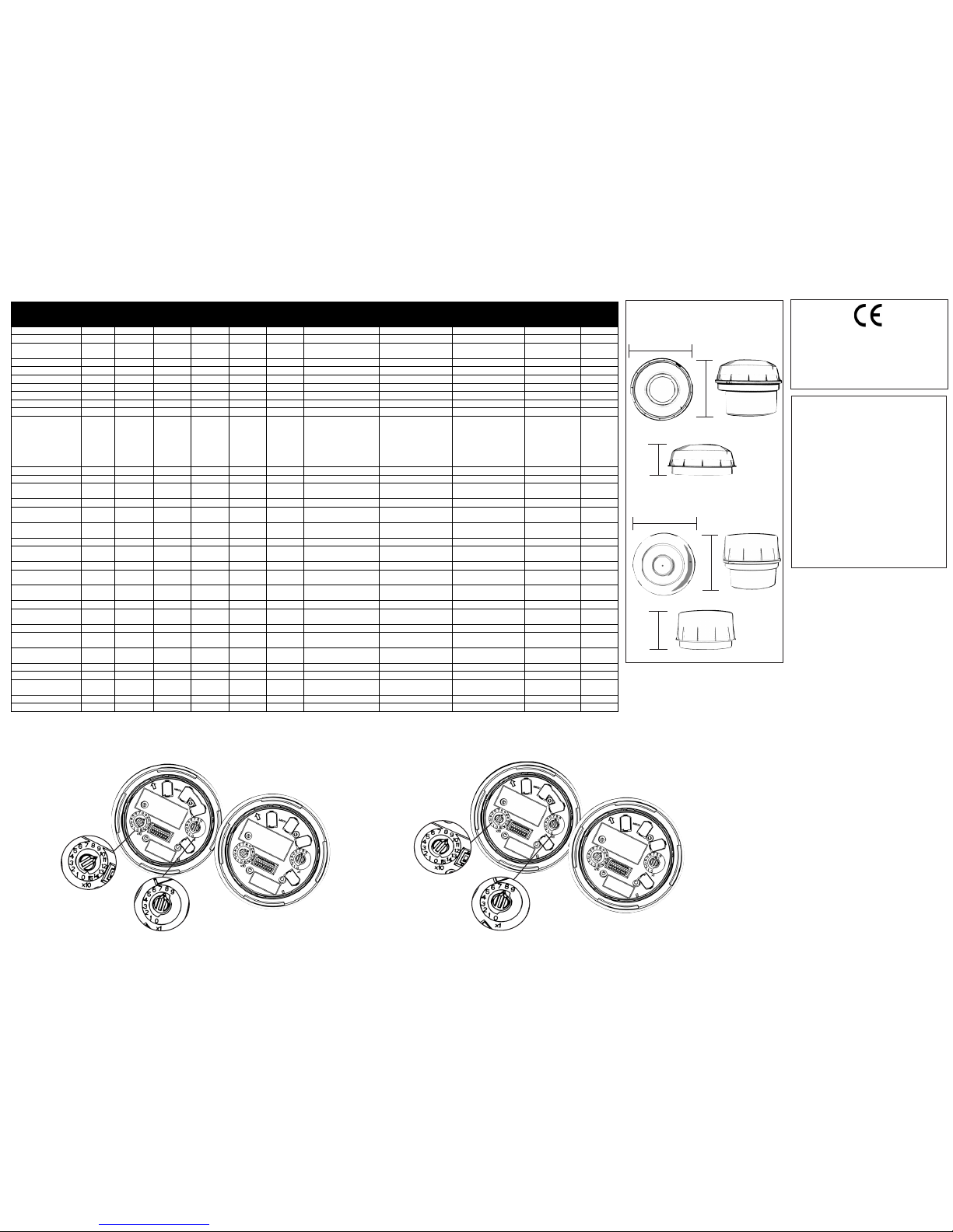
Up to 159 addresses are available. (consult the panel instructions to conrm compatibility)
These are selected via the two rotary switches. The ‘tens’ digits go from 0 to 15 and the ‘units’
from 0 to 9.
Note: if the control equipment is not capable of taking more than 99 module addresses, a fault
condition will be generated for every address over 99.
INSTALLATION INSTRUCTIONS FOR WALL MOUNTED LOOP POWERED
ADDRESSABLE SOUNDERS, SOUNDER STROBES AND STROBE ONLY
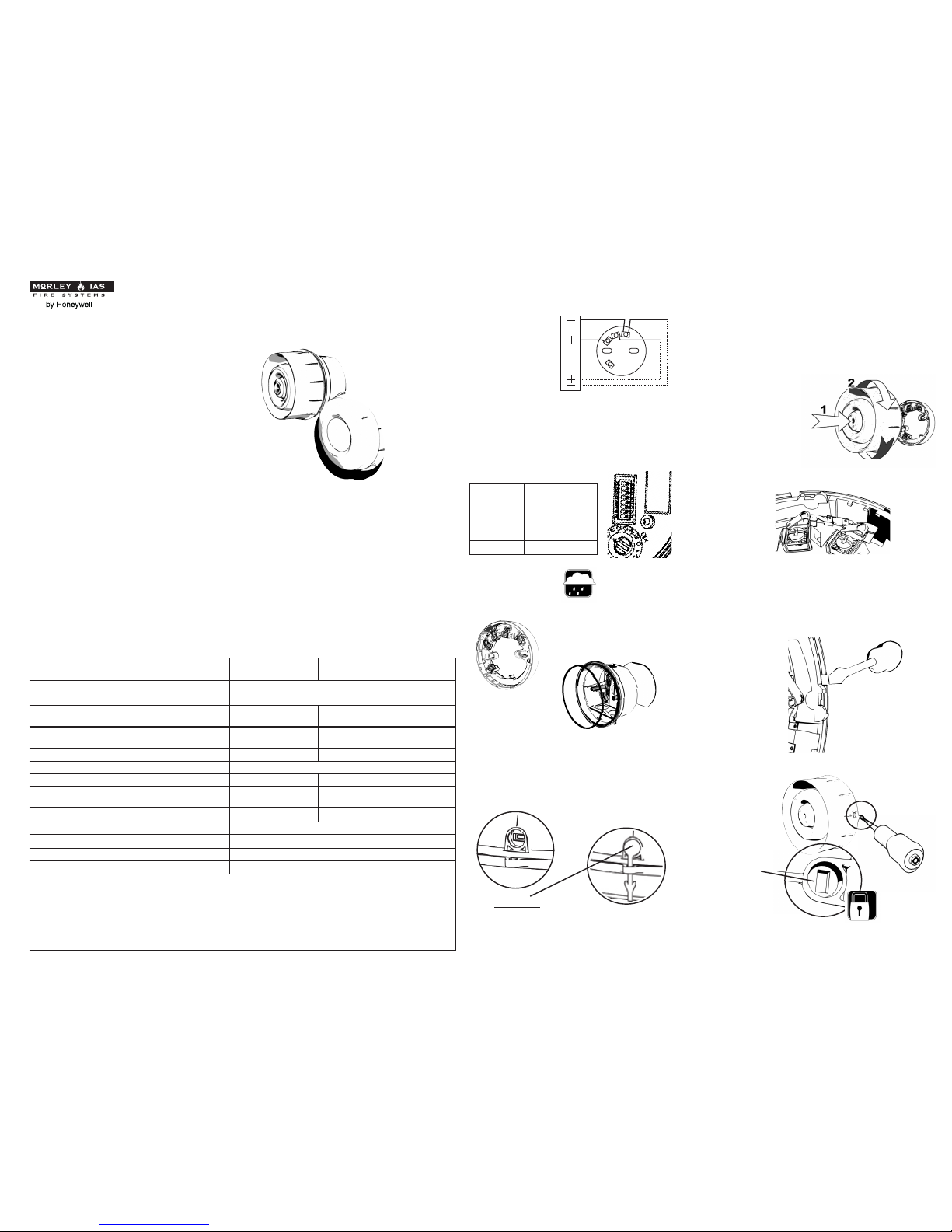
INSTALLATION
Afx B501AP to a suitably at wall. Terminate
the cable to the appropriate terminals. For
surface mount wiring the cable can enter the
B501AP base via the break outs provided.
Select the appropriate
Tone and Volume settings
via the DIP switch.
Locate the main
assembly on to the base
by rotating until it locks
into place.
CONTINUITY SPRING
The B501AP
incorporates a
continuity spring
between terminals
2 and 4. This allows
the continuity of the
eld wiring to be checked without the need for
the device to be present. Inserting the device
will disengage the spring. Removing the
device will close the loop.
ANTI TAMPER LOCK
The B501AP also
includes a tamper
resistant feature
that when activated
prevents removal of
the unit without the
use of a special tool.
This method is
consistent with the
anti tamper feature
across all devices
using this base. This
prevents the device
being turned to
enable its release.
Breakout
SPECIFICATIONS MI-WSO-XX-N
MI-WSO-XX-I
MI-WSS-XX-N
MI-WSS-XX-I
MI-WST-XX-N
MI-WST-XX-I
Signaling Line Supply Voltage (non isolation) 15 to 29VDC (24VDC typical)
Signaling Line Supply Voltage (isolation) 15 to 29VDC (24VDC typical)
Max current consumption (non isolation) (High Volume
Tone 13 @24V) 4.95mA 8.90mA N/A
Max current consumption (isolation) (High Volume Tone
13 @24V) 5.14mA 9.09mA N/A
Max peak power 146.2mW 239.8mW 99.12mW
Sound Output to EN54-3 (High Volume Tone 13 @24V) 99dB(A) ± 3dB N/A
Beacon ash rate N/A 1Hz 1Hz
Max current consumption @ 24V (non isolation) MI-WST-
XX-*
N/A N/A 3.94mA
Max current consumption @ 24V (isolation) MI-WST-XX-* N/A N/A 4.13mA
Quiescent Current 450uA
Operating temperature range -25 to +70oC
Relative humidity up to 93% (± 3%) - non condensing
Terminal Size Terminal Size 2.5mm2 - maximum
Note: This product is classied as a category `O` device to EN54:23 standard for visual alarm devices. Only variants supplied
with a clear lens will be approved to ‘O’ Class (WSS-PC-*** and WST-PC-***)
At an installation height of 2.4m and any given orientation, the specied light coverage shape and value is achieved. This
is approximately a cone of light projected at 60° base angles from the device centre with a depth and diameter of 2.0m. An
exact coverage shape can be seen by downloading the following drawing from the KAC website, 132962-IAV-O-CLASS-
EN54:23-WST.pdf, 133005-IAV-O-CLASS-EN54:23-WSS.pdf
Model types using a translucent red or amber lens are not EN54-23 approved. These model types must not be used as
visual alarm devices to provide a primary warning notication of re. For isolator specication refer to document SP11-2848 available on request
TERMINAL
CONNECTIONS
VOLUME SETTINGS
Volume setting is selected by SW6 and SW7
of the 8 way DIP switch. The appropriate tone
set is selected by SW1 to SW5 of the 8 way
DIP switch (see table 1) The 2nd stage tone
(related to the 1st stage tone) is controlled by
the re panel via the protocol.
BASES/IP RATING
B501AP (IP 21C)
Deep Back box (IP 33C)
Note: Bung seal must
be tted with the deep back box.
SW6 SW7 Volume Setting
OFF OFF HIGH
OFF ON MEDIUM
ON OFF LOW
ON ON LOW
1
2
3
4
+
_
+
_
If the deep back box option is required then
the wall gasket must be tted behind the
deep base, and the sealing o-ring tted after
attaching the low prole base.
1
2

D1007 Issue 12
Table 1 - VERSION 8C
KAC ALARM COMPANY LIMITED, KAC House, Thornhill Road, Redditch, Worcestershire, England. B98 9ND. www.kac.co.uk
DIP setting Nominal 2nd Stage
O=Off/1=On No Pattern Frequency (WSO-WSS) (WSO-WSS) (WSO-WSS) Switching Frequency Description Market Standard Tone
SW 1,2,3,4,5 High Medium Low
0,0,0,0,0 1
Alternating 525/440 5.13 /9.1 2.41 / 6.4 1.45 / 5.4 2Hz (100ms/400ms) French Fire Sound AFNOR France NFS 32-001 7
1,0,0,0,0 2
Alternating 800/922 4.42 / 8.4 1.98 / 5.9 1.38 / 5.3 1Hz UK BS5839 Pt1 8
0,1,0,0,0 3
Alternating 800/922 4.38 / 8.3 1.98 / 5.9 1.37 / 5.3 2Hz Alternating tone telecoms UK BS5839 Pt1, FP1063.1 8
1,1,0,0,0 4
Alternating 2400/2900 4.21 / 8.2 3.45 / 7.4 1.61 / 5.6 3Hz Alternating High Frequency 10
0,0,1,0,0 5
Alternating 2500/3100 5.49 / 9.4 4.09 / 8.0 1.56 / 5.5 2Hz Security Alarm 10
1,0,1,0,0 6
Alternating 988/645 5.61 / 9.6 2.21 / 6.2 1.49 / 5.4 2Hz 8
0,1,1,0,0 7
Continuous 630 5.19 / 9.1 1.81 / 5.8 1.12 / 5.1 All clear Sweden 1
1,1,1,0,0 8
Continuous 922 5.10 / 9.0 2.08 / 6.0 1.44 / 5.4 BS 5839 Pt 1 2
0,0,0,1,0 9
Continuous 1200 4.98 / 8.9 2.10 / 6.0 1.74 / 5.7 2
1,0,0,1,0 10
Continuous 2810 4.96 / 8.9 3.00 / 6.9 1.42 / 5.4 HF Continuous 4
0,1,0,1,0 11
Sweep 150-1000 5.90 / 9.8 2.10 / 6.0 1.55 / 5.5
Rising from 150Hz to 1000Hz in
10 seconds, then 40 seconds at
1000Hz, then falling from
1000Hz to 150Hz in 10
seconds, then 20 seconds at
150Hz, then repeating. Total
p
eriod 80 seconds.
“Gasalarm” Tone 22
1,1,0,1,0 12 Intermittent 420
5.86 / 9.8 2.40 / 6.3 1.42 / 5.4
0.625s on, 0.625 sec off AS2220 alert tone NZ, Aus AS2220
13
0,0,1,1,0 13 Sweep 500-1200
4.95 / 8.9 2.76 / 6.7 2.31 / 6.3
0.25 sec off, 3.75 sec on AS2220 evacuate tone NZ, Aus AS2220
12
1,0,1,1,0 14
Intermittent 630 4.36 / 8.3 2.00 / 5.9 1.03 / 5.0 3.33Hz 150ms on, 150ms off Swedish alarm tone Sweden 7
0,1,1,1,0 15
Intermittent 922 3.86 / 7.8 1.76 / 5.7 1.27 / 5.2 0.8Hz 0.25s on, 1s off Intermittent Tone UK BS 5839 Pt 1 8
1,1,1,1,0 16
Intermittent 922 3.97 / 7.9 1.73 / 5.7 1.29 / 5.2 0.5Hz 1s on, 1s off Back up alarm LF & BS5839
Pt 1 UK BS5839 Pt 1 8
0,0,0,0,1 17
Intermittent 2810 3.65 / 7.6 2.97 / 6.9 1.43 / 5.4 1Hz Back up alarm HF & BS5839
Pt 1 2nd tone UK BS5839 Pt 1 10
1,0,0,0,1 18
Intermittent 922 3.97 / 7.9 1.73 / 5.7 1.29 / 5.2 1Hz 500ms on, 500ms off LF BS5839 Pt 1 UK BS5839 Pt 1 8
0,1,0,0,1 19
Intermittent 950 4.38 / 8.3 1.76 / 5.7 1.32 / 5.3 0.22Hz (0.5s on, 0.5s off) rptx3,
1.5s off Australia ISO8201 12
1,1,0,0,1 20
Continuous 800 4.51 / 8.5 1.98 / 5.9 1.37 / 5.3 BS 5839 Pt 1 22
0,0,1,0,1 21
Sweep 400-1200 5.00 / 8.9 2.31 / 6.3 1.52 / 5.5 (0.5s on, 0.5s off)*3, 1.5s off Temporal 3 Evacuation tone Australia ISO8201 Temporal 3 12
1,0,1,0,1 22
Sweep 1200 - 500 4.89 / 8.8 2.44 / 6.4 1.62 / 5.6 0.99Hz 1s on, 0.01s off Evacuate, DIN tone & PFEER Germany DIN, PFEER 20
0,1,1,0,1 23
Sweep 2400 - 2850 4.28 / 8.2 3.36 / 7.3 1.56 / 5.5 7Hz Fast sweep VdS Germany VdS 10
1,1,1,0,1 24
Sweep 500 - 1200 4.98 / 8.9 2.73 / 6.7 2.33 / 6.3 (0.5s off, 3.5s on) Slow whoop evacuate
Netherlands Netherlands NEN 2575 8
0,0,0,1,1 25
Sweep 800 - 970 4.65 / 8.6 2.13 / 6.1 1.35 / 5.3 50Hz LF Buzz BS5839 Pt 1 UK BS5839 Pt 1 8
1,0,0,1,1 26
Sweep 800 - 970 3.48 / 7.4 1.85 / 5.8 1.41 / 5.4 7Hz Fast sweep LF BS5839 Pt 1 UK BS5839 Pt 1 8
0,1,0,1,1 27
Sweep 800 - 970 3.40 / 7.3 1.99 / 5.9 1.42/ 5.4 1Hz Medium sweep LF, BS5839 Pt
1, VdS UK, Germany BS5839 Pt 1 VdS 8
1,1,0,1,1 28
Sweep 2400 – 2850 4.26 / 8.2 3.37 / 7.3 1.71 / 5.7 50Hz High frequency buzz 10
0,0,1,1,1 29
Sweep 500 – 1000 4.20 / 8.1 1.71 / 5.7 1.19 / 5.1 7Hz Fast whoop 8
1,0,1,1,1 30
Sweep 500 – 1200 –
500 5.02 / 9.0 2.58 / 6.5 1.96 / 5.9 0.166Hz rise 1s, stable 4s, fall
1s Siren style tone 8
0,1,1,1,1 31
Sweep 800 – 1000 4.61 / 8.6 3.31 / 7.3 1.44 / 5.4 2Hz 8
1,1,1,1,1 32
Sweep 2400 - 2850 4.31 / 8.3 3.54 / 7.4 1.61 / 5.6 1Hz 10
Maximum consumption (mA)
121mm
106mm
62mm 51mm
94mm
DIMENSIONS
Strobe
For Isolated variants add 0.19mA
to high,medium, low values
above.
We reserve the right to amend
the content of this document
without prior notice.
Sounder Output data, in
accordance with EN54-3, is
available on Document Ref:
D 1022.
0832
For CPD/CPR Data on all
relevant devices please request
D974.
IMPORTANT NOTES:
Sounder/SounderStrobe
121mm
ADDRESS SETTING
To set one of the 159 available addresses for the device use the two rotary switches located either side of the dip switch unit. The ‘tens’ digits go from 0 to 15 and the ‘units’ from 0 to 9.
Example A (Address setting 108)
Non-Isolated
Isolated Isolated
Non-Isolated
Example B (Address setting 98)
This manual suits for next models
5
Other MORLEY-IAS Marine Equipment manuals