WARNINGS AND CAUTIONS
Page 3 of 21
The installation must conform with local codes
or, in the absence of local codes, with the
National Fuel Gas Code, ANSI Z223.1/NFPA 54,
NFPA58 Natural Gas and Propane Installation
Code, CSA B149.1, or Propane Storage and
Handling Code, B149.2
Children and adults should be alerted to the
hazards of high surface temperatures and
should stay away to avoid burns or clothing
ignition.
Young children should be carefully
supervised when they are in the area of the
heater.
Clothing or other flammable materials
should not be hung from the heater, or
placed on or near the heater.
Any guard or other protective device
removed for servicing the heater must be
replaced prior to operating the heater.
Installation and repair should be done by a
qualified service person. The heater should
be inspected before use and at least
annually by a qualified service person.
More frequent cleaning may be required as
necessary. It is imperative that control
compartment, burners and circulating air
passageways of the heater be kept clean.
Keeping the appliance area clear and free from
combustible materials, gasoline and other
flammable vapors and liquids.
Keeping the ventilation opening(s) of the
This appliance shall be used only in a well
ventilated space and shall not be used in a
An appliance may be installed with shelter
With walls on all sides, but with no overhead
NOTE:PLEASE READ THE FOLLOWING SAFETY RULES
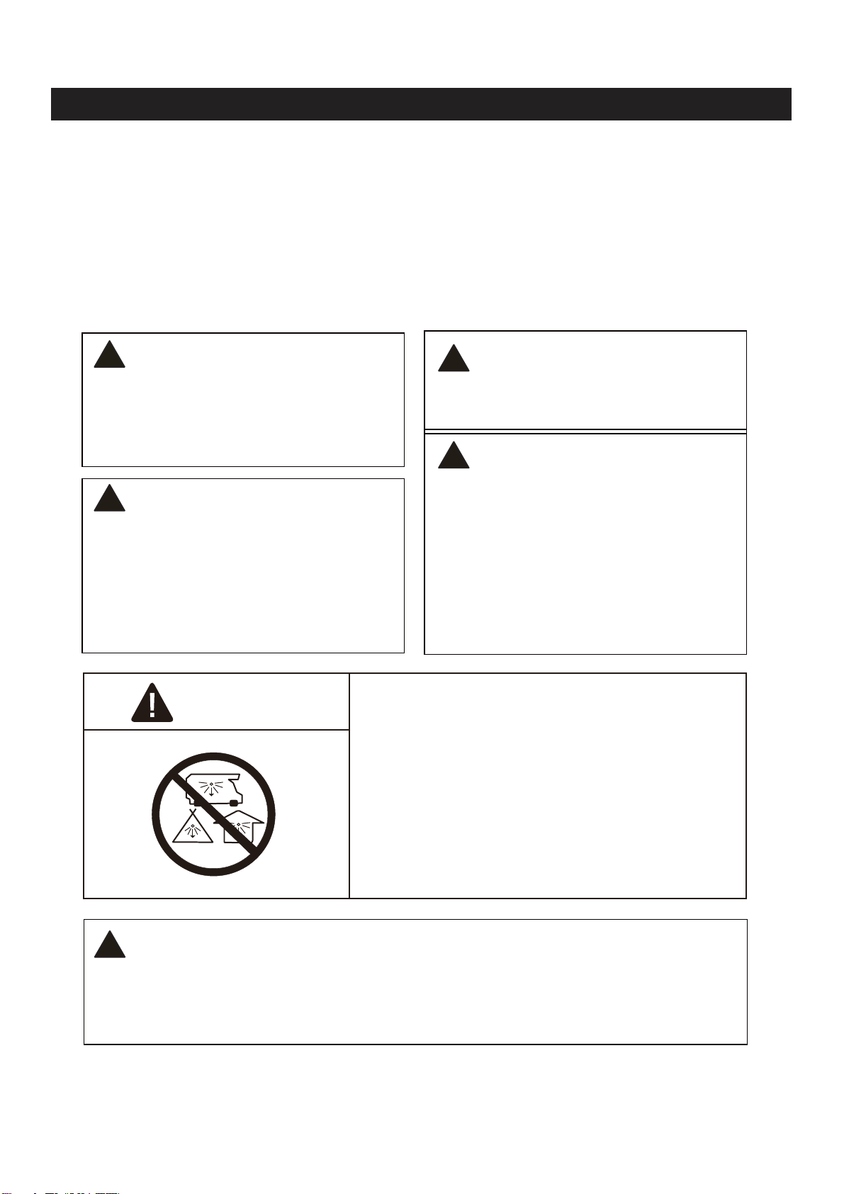
WARNING:
DO NOT OBSTRUCT the flow of combustion
!
The heater, when installed, must be electrically
grounded in accordance with local codes or, in
the absence of local codes, with the National
Electrical Code, ANSI/NFPA 70, or the Canadian
Electrical Code, CSA C22.1.
Prior to use, check for damaged parts such as
hoses, regulators, pilot or burner.
All leak tests should be done with a soapy
solution. NEVER USE AN OPEN FLAME TO
CHECK FOR LEAKAGE.
The propane hose with regulator assembly shall
be located out of pathways where people may
trip over it or in areas where the hose will not be
subject to accidental damage. and ventilation air.
cylinder enclosure free and clear from debris.
building, garage or any other enclosed area.
no more inclusive than:
cover.
Within a partial enclosure which includes an
overhead cover and no more than two side
walls. These side walls may be parallel, as in
a breezeway, or at right angles to each other.